Table of Contents
Advertisement
Advertisement
Table of Contents

Related Manuals for NCR RealPOS 50

Summary of Contents for NCR RealPOS 50
- Page 1 NCR RealPOS 50 (7611) Release 1.1 User Guide B005‐0000‐2017 Issue C...
- Page 2 The product described in this book is a licensed product of NCR Corporation. NCR is a registered trademark of NCR Corporation. NCR RealPOS is a trademark of NCR Corporation in the United States and/or other countries. Other product names mentioned in this publication may be trademarks or registered trademarks of their respective companies and are hereby acknowledged. Where creation of derivative works, modifications or copies of this NCR copyrighted documentation is permitted under the terms and conditions of an agreement you have with NCR, NCRʹs copyright notice must be included. It is the policy of NCR Corporation (NCR) to improve products as new technology, components, software, and firmware become available. NCR, therefore, reserves the right to change specifications without prior notice. All features, functions, and operations described herein may not be marketed by NCR in all parts of the world. In some instances, photographs are of equipment prototypes. Therefore, before using this document, consult with your NCR representative or NCR office for information that is applicable and current. To maintain the quality of our publications, we need your comments on the accuracy, clarity, organization, and value of this book. Address correspondence to: Manager, Information Solutions Group NCR Corporation Discovery Centre, 3 Fulton Road Dundee, DD2 4SW Scotland Internet Address: http://www.info.ncr.com/eFeedback.cfm Copyright © 2010 By NCR Corporation Duluth, GA U.S.A. All Rights Reserved...
- Page 3 Preface Audience This book is written for hardware installer/service personnel, system integrators, and field engineers. Notice: This document is NCR proprietary information and is not to be disclosed or reproduced without consent. Safety Requirements The NCR RealPOS 50 conforms to all applicable legal requirements. To view the compliance statements see the NCR RealPOS Terminals Safety and Regulatory Statements (B005‐0000‐1589). Caution: The on/off switch is a logic switch only. The AC line voltage primaries are live at all times when the power cord is connected. Therefore, disconnect the AC power cord before opening the unit to install features or service this terminal. Caution: This product does not contain user serviceable parts. Servicing should only be performed by a qualified service technician. Fuse Replacement Warning: For continued protection against risk of fire, replace only with the same type and ratings of fuse. Attention: Pour prévenir et vous protéger contre un risque de feu, remplacer la fusible avec une autre fusible de même type, seulement. Lithium Battery Warning Warning: Danger of explosion if battery is incorrectly replaced. Replace only with the same or equivalent type as recommended by the manufacturer. Discard used batteries according to the manufacturerʹs instructions. Attention: Il y a danger dʹexplosion sʹil y a remplacement incorrect de la batterie. Remplacer uniquement avec une batterie du même type ou dʹun type recommandé par le constructeur. Mettre au rébut les batteries usagées conformément aux instructions du fabricant. Battery Disposal (Switzerland) Refer to Annex 4.10 of SR814.013 for battery disposal.
- Page 4 Warning: DO NOT connect or disconnect any serial peripherals while the terminal is connected to AC power. This can result in system or printer damage. Grounding Instructions In the event of a malfunction or breakdown, grounding provides a path of least resistance for electric current to reduce the risk of electric shock. This product is equipped with an electric cord having an equipment‐grounding conductor and a grounding plug. The plug must be plugged into a matching outlet that is properly installed and grounded in accordance with all local codes and ordinances. Do not modify the plug provided – if it will not fit the outlet, have the proper outlet installed by a qualified electrician. Improper connection of the equipment‐grounding conductor can result in a risk of electric shock. The conductor with insulation having an outer surface that is green with or without yellow stripes is the equipment‐grounding conductor. If repair or replacement of the electric cord or plug is necessary, do not connect the equipment‐grounding conductor to a live terminal. Check with a qualified electrician or service personnel if the grounding instructions are not completely understood, or if you are in doubt as to whether the product is properly grounded. Use only 3‐wire extension cords that have 3‐prong grounding plugs and 3‐pole receptacles that accept the product’s plug. Repair or replace damaged or worn cords immediately. References • NCR RealPOS 50 Site Preparation Guide (B005‐0000‐2035) • NCR RealPOS 50 Hardware Service Manual (B005‐0000‐2036) • NCR RealPOS 50 Parts Identification Manual (B005‐0000‐2037) Revision Record Issue Date Remarks Oct 2010 First Issue July 2012 Updated Solid State Optimization chapter Dec 2012 Release 1.1...
-
Page 5: Table Of Contents
G1 Sleeping . . . . . . . . . . . . . . . . . . . . . . . . . . . . . . . . . . . . . . . . . . . . 1‐14 G0 Working. . . . . . . . . . . . . . . . . . . . . . . . . . . . . . . . . . . . . . . . . . . . 1‐14 ACPI Sleep States (S0 ‐ S5) . . . . . . . . . . . . . . . . . . . . . . . . . . . . . . . 1‐15 Enabling Wake on LAN . . . . . . . . . . . . . . . . . . . . . . . . . . . . . . . . . 1‐17 Windows 7 . . . . . . . . . . . . . . . . . . . . . . . . . . . . . . . . . . . . . . . . . 1‐17 Windows XP. . . . . . . . . . . . . . . . . . . . . . . . . . . . . . . . . . . . . . . . 1‐20 ACPI Processor C‐States . . . . . . . . . . . . . . . . . . . . . . . . . . . . . . . . . 1‐22 Customer Displays . . . . . . . . . . . . . . . . . . . . . . . . . . . . . . . . . . . . . . . . . 1‐22 5942 12.1‐Inch Color LCD . . . . . . . . . . . . . . . . . . . . . . . . . . . . . . . . 1‐24 5942 15‐Inch Color LCD . . . . . . . . . . . . . . . . . . . . . . . . . . . . . . . . . 1‐25 5965 15‐Inch Touch Screen . . . . . . . . . . . . . . . . . . . . . . . . . . . . . . . 1‐25 5966 15‐Inch Touch Screen . . . . . . . . . . . . . . . . . . . . . . . . . . . . . . . 1‐27 Features . . . . . . . . . . . . . . . . . . . . . . . . . . . . . . . . . . . . . . . . . . . . 1‐27 NCR 5982 6.5‐Inch LCD Display . . . . . . . . . . . . . . . . . . . . . . . . . . 1‐28 Keyboards . . . . . . . . . . . . . . . . . . . . . . . . . . . . . . . . . . . . . . . . . . . . . . . . 1‐29 5932 Keyboards . . . . . . . . . . . . . . . . . . . . . . . . . . . . . . . . . . . . . . . . 1‐29... - Page 6 Keyboard Power . . . . . . . . . . . . . . . . . . . . . . . . . . . . . . . . . . . . 1‐29 NCR 5932‐5xxx USB Alphanumeric Big Ticket Keyboard. . . . . 1‐30 Features . . . . . . . . . . . . . . . . . . . . . . . . . . . . . . . . . . . . . . . . . . . . 1‐30 NCR 5932‐65xx PS/2 Programmable POS Keyboard . . . . . . . . . 1‐31 NCR 5932‐66xx USB Programmable POS Keyboard . . . . . . . . . 1‐32 NCR 5975 2x20 VFD Customer Display . . . . . . . . . . . . . . . . . . . . 1‐33 Features . . . . . . . . . . . . . . . . . . . . . . . . . . . . . . . . . . . . . . . . . . . . 1‐33 Character Sets. . . . . . . . . . . . . . . . . . . . . . . . . . . . . . . . . . . . . . . 1‐34 Integrated 2x20 Customer Display . . . . . . . . . . . . . . . . . . . . . . . . 1‐35 Features . . . . . . . . . . . . . . . . . . . . . . . . . . . . . . . . . . . . . . . . . . . . 1‐35 Character Sets. . . . . . . . . . . . . . . . . . . . . . . . . . . . . . . . . . . . . . . 1‐35 NCR 7167 Printer . . . . . . . . . . . . . . . . . . . . . . . . . . . . . . . . . . . . . . . 1‐36 7168 Printer . . . . . . . . . . . . . . . . . . . . . . . . . . . . . . . . . . . . . . . . . . . . 1‐37 7197 Printer . . . . . . . . . . . . . . . . . . . . . . . . . . . . . . . . . . . . . . . . . . . . 1‐38 NCR 7198 Printer . . . . . . . . . . . . . . . . . . . . . . . . . . . . . . . . . . . . . . . 1‐38 Chapter 2: Hardware Installation...
- Page 7 Installing a 5982 6.5‐Inch LCD . . . . . . . . . . . . . . . . . . . . . . . . . . . . 2‐22 Installing an NCR 5975 Customer Display. . . . . . . . . . . . . . . . . . 2‐26 RS‐232 Interface (Powered) . . . . . . . . . . . . . . . . . . . . . . . . . . . 2‐28 USB Interface (Powered) . . . . . . . . . . . . . . . . . . . . . . . . . . . . . 2‐29 Installing a Secondary Display (Dual Display) . . . . . . . . . . . . . . . . . 2‐30 Dual Display Clone . . . . . . . . . . . . . . . . . . . . . . . . . . . . . . . . . . . . . 2‐31 Extended Desktop Dual Display . . . . . . . . . . . . . . . . . . . . . . . . . . 2‐32 Single Display Mode . . . . . . . . . . . . . . . . . . . . . . . . . . . . . . . . . . . . 2‐33 Intel Graphics Controller Hot Keys. . . . . . . . . . . . . . . . . . . . . . . . 2‐34 Installing a Cash Drawer . . . . . . . . . . . . . . . . . . . . . . . . . . . . . . . . . . . . 2‐35 Second Cash Drawer Cable Connection . . . . . . . . . . . . . . . . . . . . 2‐36 Replacing the Hard Disk Drive . . . . . . . . . . . . . . . . . . . . . . . . . . . . . . 2‐37 Chapter 3: Touch Screen Calibration Installing and Calibrating the Touch Screen . . . . . . . . . . . . . . . . . . . . 3‐1 Installing the Driver. . . . . . . . . . . . . . . . . . . . . . . . . . . . . . . . . . . . . . 3‐1 Calibrating the Touch Screen . . . . . . . . . . . . . . . . . . . . . . . . . . . . . . 3‐3 Calibration Procedures . . . . . . . . . . . . . . . . . . . . . . . . . . . . . . . . . . . ...
- Page 8 viii Prerequisites . . . . . . . . . . . . . . . . . . . . . . . . . . . . . . . . . . . . . . . . . . . . 6‐1 Creating the Bootable Media. . . . . . . . . . . . . . . . . . . . . . . . . . . . . . . . . . 6‐2 Creating a Bootable CD . . . . . . . . . . . . . . . . . . . . . . . . . . . . . . . . . . . 6‐2 Creating a Bootable USB Memory Drive . . . . . . . . . . . . . . . . . . . . 6‐2 BIOS Updating Procedures . . . . . . . . . . . . . . . . . . . . . . . . . . . . . . . . . . . 6‐3 Manually Updating the MAC Address . . . . . . . . . . . . . . . . . . . . . . . . . 6‐5 Chapter 7: Solid State Drive Optimization About the Intel® SSD Optimizer . . . . . . . . . . . . . . . . . . . . . . . . . . . . . . 7‐1 Intel® SSD Optimizer Requirements . . . . . . . . . . . . . . . . . . . . . . . 7‐1 Installation and Startup . . . . . . . . . . . . . . . . . . . . . . . . . . . . . . . . . . . . . . 7‐3 Requirements . . . . . . . . . . . . . . . . . . . . . . . . . . . . . . . . . . . . . . . . . . . 7‐3 Installation. . . . . . . . . . . . . . . . . . . . . . . . . . . . . . . . . . . . . . . . . . . . . . 7‐3 Start Intel SSD Toolbox . . . . . . . . . . . . . . . . . . . . . . . . . . . . . . . . . . . 7‐4 Manually Running the Intel® SSD Optimizer . . . . . . . . . . . . . . . . 7‐5 Scheduling the Intel® SSD Optimizer. . . . . . . . . . . . . . . . . . . . . . . 7‐8 Removing a Scheduled Intel® SSD Optimizer Session . . . . . . . 7‐11 Additional Information . . . . . . . . . . . . . . . . . . . . . . . . . . . . . . . . . . . . . ...
- Page 9 CP866. . . . . . . . . . . . . . . . . . . . . . . . . . . . . . . . . . . . . . . . . . . . . . . 9‐7 CP932. . . . . . . . . . . . . . . . . . . . . . . . . . . . . . . . . . . . . . . . . . . . . . . 9‐8 Chapter 10: Touch Screen Operation Introduction. . . . . . . . . . . . . . . . . . . . . . . . . . . . . . . . . . . . . . . . . . . . . . . 10‐1 Touch Mode of Operation . . . . . . . . . . . . . . . . . . . . . . . . . . . . . . . . . . . 10‐1 Changing the Touch Mode . . . . . . . . . . . . . . . . . . . . . . . . . . . . . . . 10‐2 Turning Off the Mouse Pointer . . . . . . . . . . . . . . . . . . . . . . . . . . . . . . 10‐3 Terminal Placement . . . . . . . . . . . . . . . . . . . . . . . . . . . . . . . . . . . . . . . . 10‐5 Appendix A: Powered Serial Port Settings Appendix B: Disabling USB Ports for Security Purposes Appendix A: Display Color Adjustment...
-
Page 11: Chapter 1: Product Overview
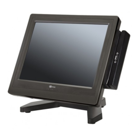
Product Overview Chapter 1: Introduction The NCR RealPOS 50 (also known as NCR 7611) is a compact POS solution that combines the reliability and security of a retail‐hardened POS terminal with the performance and flexibility of industry‐standard PC technology. With an open architecture and Intel® processor, the NCR RealPOS 50 supports the latest POS applications for Windows® to help you service your customers quickly and efficiently. And, it all fits in a small footprint that helps conserve valuable space at the Checkstand. To complete your POS solution, choose from NCRʹs extensive line of peripherals, including printers, displays, keyboards and scanners. The NCR RealPOS 50 enables you to protect your investment in legacy serial devices or choose from the growing list of USB peripherals. The powered peripheral ports and 24V printer interface simplify cable management and reduce potential points of failure. Product IDs Major Model 7611‐3001 Resistive, Intel Celeron 900, 1 GB DDR3 1066 MHz, 2.5ʺ 250GB 7611‐4001 Capacitive, Intel Dual‐Core T3100, 2 GB DDR3 1066 MHz, 2.5ʺ 250GB HDD 7611‐4010 Capacitive, Intel Dual‐Core T3100, 2 GB DDR3 1066 MHz, 2.5ʺ 40GB SSD... -
Page 12: Features
Product Overview Features 7611 Processor Board • Intel GL40 Chipset • Processors • Intel Celeron Processor 900 • Intel Dual‐Core T3100 • Up to 2GB DDR2 Memory • Serial ATA (SATA) Hard Drive Interface • Option for single 2.5ʺ Hard Drive • Memory; two slots (1GB Std, 8GB Max.) • High‐speed 10/100/1000Mb Ethernet • Four USB Ports: • 2 USB (5V) • 1 Powered USB (24V printer) • 1 Powered USB (12V) • Four Serial ports (DB9) • 3 Powered RS‐232 (selectable 0/5/12V) • 1 (Optional, available if there is no 2x20 present • DVI‐D connector •... -
Page 13: Integrated Options
Product Overview Integrated Options • Table Top Stand • Integrated Customer Display Base • 2x20 VFD Customer Display • 6.5ʺ, 12ʺ, 15ʺ LCD Customer Displays • Color Bezels • MSR • MSR with Biometric Fingerprint Reader Storage Media • Primary 2.5ʺ SATA Hard Drive • Solid State Drive ‐ SATA interface Power Supply • 150W Output power • Switching Power Supply, External 24V Adapter • MEPS Level V mark (efficiency 87% minimum), Energy Star 5.0 capable • Supports 24V retail printers at 55W maximum when connected to 7611 Operating Systems • Windows 7 Professional • Windows XP Professional, SP3 •... -
Page 14: Energy Star
Product Overview Energy Star ENERGY STAR® qualified products and practices help you save money and reduce greenhouse gas emissions by meeting strict energy efficiency guidelines set by the U.S. Environmental Protection Agency (EPA) and the U.S. Department of Energy. You can help reduce electricity usage and its environmental impact by power managing your POS product when it is not in use for extended periods of time. What are the potential benefits of the new Energy Star® Specification? Desktops (including POS terminals), Notebooks, and Workstations manufactured after July 1, 2009 that display the ENERGY STAR® label meet the more stringent 5.0 requirements. Because of these requirements, your computer has a highly efficient power supply and other hardware specific features that, based on EPA estimates, could annually: • Save you up to 115 kWh of electricity per unit • Prevent up to 200 lbs of green house gas emissions per unit Moreover, ENERGY STAR® compliant computers can save even more energy by using ENERGY STAR® power management features, which allow the computer to enter a very low power mode when not in use for a specified period of time. The EPA estimates that these power management features, when enabled on ENERGY STAR® qualified computers, could save you up to 115 kWh of electricity annually (per unit). This is equivalent to: • Saving greenhouse gas emissions by taking your car off the road for 5 days • Planting a grove of trees 46 ft. by 46 ft Power Management Settings •... - Page 15 Product Overview b. Select Device Manager in the System Tools section. Expand Mice and other pointing devices and then right‐mouse click on USB Touch Screen Controller.
-
Page 16: More Information About Energy Star
Product Overview d. Select the Power Management tab. The Allow this device to bring the computer out of standby option is active by default. Un‐check the check box. 2. The POS cannot be awakened from Standby Mode via Touch if the Touch device is connected to a +12V USB port. Power is removed from the +12V USB and without power Touch events cannot be detected. 3. After waking from Standby (via keyboard, mouse, or power switch), touch will not respond for approximately 30 seconds. This delay can be reduced significantly by changing disabling the Allow this device to bring the computer out of standby option as discussed in Step #1 above. 4. If wake from standby via Touch is required, the Touch Display must be powered from an independent source such as a power brick. If the Touch Display is powered by power brick, issues noted in 1), 2), and 3) no longer apply. More Information about Energy Star ENERGY STAR compliant systems combined with power management settings can ® provide NCR customers the greatest TCO (total cost of ownership) savings2! Go to www.energystar.gov/powermanagement to learn more about power management. For more information on ENERGY STAR go to www.energystar.gov ... -
Page 17: Configurations
Product Overview Configurations The NCR RealPOS 50 is an affordable, retail‐ready POS solution that provides outstanding value for any size retailer. It supports a broad range of certified NCR peripherals and applications. The RealPOS 50 features the smallest form factor in its class and offers versatile configuration and mounting options. Choose from NCRʹs extensive line of peripherals, including printers, displays, keyboards and scanners. The RealPOS 50 provides flexible connectivity options to power peripherals as well as dual display support for customer‐facing advertising and messaging. The system can be configured as a standalone unit or stacked on an NCR 2181 Cash Drawer in an integrated fashion. Below are a couple of examples. Table Top Stand Configuration Table Top Stand w/Power Supply Enclosure Integrated Configuration... -
Page 18: Operator Controls
Product Overview Operator Controls Power Switch The power switch is located behind the Cable Cover. Power Switch 29236 Power and Disk Activity LEDs The Power and Disk Activity LEDs are located on the front of the unit. 29237 Power LED Disk Activity LED... -
Page 19: Led Diagnostic Indicators
Product Overview LED Diagnostic Indicators The two front panel LEDs also function as diagnostic indicators, defined as follows. Note: The cell colors indicate the color of the LED at that particular time. Current System Disk Activity Suspect Component System State Power LED Corrective Action Operation Normal Opera‐ System ON tion Normal Opera‐ System ON Flashing tion with HDD (HDD Activity Access) Normal Opera‐ Unit in Sus‐ Blinking (1/ tion pend (S3) Sec) ‐ OFF • OFF ‐ AC Present •... - Page 20 1-10 Product Overview Current System Disk Activity Suspect Component System State Power LED Corrective Action Operation Runtime Cooling Com‐ Over Tempera‐ Flashes 1. Check for blocked ponent/CPU ture red/green, cooling vents then solid 2. Check for excessive red as tem‐ ambient temperature perature 3. Check cooling increases components POST CPU not Oper‐ 1. Check for correctly ating installed CPU 2.
- Page 21 Product Overview 1-11 Current System Disk Activity Suspect Component System State Power LED Corrective Action Operation Boot Time Boot Media HDD is Boot Device: (HDD, LAN) 1. Check HDD status in BIOS Setup 2. Check connections between HDD and Motherboard 3. Replace or re‐image 4. Replace Motherboard LAN is Boot Device: 1. Check for LAN link and activity LEDs on the Back Panel 2. Check LAN cable 3. Replace Motherboard...
-
Page 22: Label Locations
1-12 Product Overview Label Locations The serial number and model number are included on the Certification Label located under the Cable Cover of the terminal. A Microsoft Certificate of Authenticity (COA) label is included if the terminal is ordered and shipped with a pre‐installed Microsoft Operating System. There are two types of Microsoft COA stickers. Depending on the Microsoft Operating System ordered the label is located on either the Back Cover for XP Professional and Windows 7 OR next to the Certification Label under the Cable Cover for XP Embedded, WEPOS, POSReady 2009, and POSReady 7. Certificate of Authenticity Certification Certificate of Authenticity (Large) (Small) 29238 Weights & Measures Label 7610 NCR Model: Approval: NCR Model: 7610 Approval: 29257... -
Page 23: Power Management
Product Overview 1-13 Power Management The BIOS supports the Advanced Configuration and Power Management Interface (ACPI) 2.0 specification. A key feature of ACPI is that the operating system, not the BIOS, configures and implements power management. The 7611 terminal supports the Global system power states defined by ACPI: G3 Mechanical Off A computer state that is entered and left by a mechanical means Example: Turning off the systemʹs power through the movement of a large red switch. Various government agencies and countries require this operating mode. It is implied by the entry of this off state through a mechanical means that no electrical current is running through the circuitry and that it can be worked on without damaging the hardware or endangering service personnel. The OS must be restarted to return to the Working state. No hardware context is retained. Except for the real‐time clock, power consumption is zero. G2/S5 Soft Off A computer state where the computer consumes a minimal amount of power. No user mode or system mode code is run. This state requires a large latency in order to return to the Working state. The systemʹs context will not be preserved by the hardware. The system must be restarted to return to the Working state. It is not safe to disassemble the machine in this state. G1 Sleeping A computer state where the computer consumes a small amount of power, user mode threads are not being executed, and the system appears to be off (from an end userʹs perspective, the display is off, and so on). Latency for returning to the Working state varies on the wake environment selected prior to entry of this state (for example, whether the system should answer phone calls). Work can be resumed without rebooting the OS because large elements of system context are saved by the hardware and the rest by system software. It is not safe to disassemble the machine in this state. G0 Working A computer state where the system dispatches user mode (application) threads and ... -
Page 24: Acpi Sleep States (S0 - S5)
ACPI Sleep States (S0 - S5) Under the G1 sleeping state ACPI defines levels of system sleep state support. The 7611 supports the following sleeping states: • S0: Normal Powered‐On state • S1 (Standby): The S1 sleeping state is a low wake latency sleeping state. In this state, no system context is lost (CPU or chip set) and hardware maintains all system contexts. Note: The 7611 does not support S1 state. Turning off the backlight and hard drives provides the equivalent power savings (due to Intelʹs processor C‐states feature) at nearly zero latency. • S2: Not supported • S3 (Suspend to Ram): The S3 sleeping state is a low wake latency sleeping state. This state is similar to the S1 sleeping state except that the CPU and system cache context is lost (the OS is responsible for maintaining the caches and CPU context). Control starts from the processorʹs reset vector after the wake event. In NCR systems, during S3, power is only provided to the on‐board USB ports. Note: When the terminal resumes from an S3 state, all the USB devices re‐ enumerate. This causes speaker tones as if they were disconnected and then reconnected. This does not present a problem and the USB devices will continue to operate correctly. Requirements for S3 support: • O/S must be built on a system with S3 enabled in the BIOS • Some peripherals may not be S3 capable, which can prevent the system from entering S3 state. • ʺS4 (Suspend to Disk): The S4 state is the lowest power, longest wake latency sleeping state supported by ACPI. In order to reduce power to a minimum, it is assumed that the hardware platform has powered off all devices. Platform context is maintained. ... - Page 25 Product Overview 1-15 **S3 **S5 Power State Suspend to Working Standby Hibernate Soft Off Supported: Y / N Video Off / Off, Memory Off, Memory Description Fully HDD Off in Slow Image Written Functional Refresh to HDD Power Supply Status Powered Powered Powered...
-
Page 26: Enabling Wake On Lan
1-16 Product Overview Enabling Wake on LAN In order for Wake on LAN to function the Network driver must be enabled (factory default). The procedure for enabling the driver depends on which operating system you are using. Windows 7 → → Properties Tab → Select Start Computer System Device Manager Select Network adapters and then ... - Page 27 Product Overview 1-17 3. Right‐mouse click the Realtek PCIe FE Family Controller driver and then select Properties. 4. Under the Advanced tab both Wake on Magic Packet and Wake on Pattern Match should be Enabled. Select OK after making any changes.
- Page 28 1-18 Product Overview 5. Under the Power Management tab all option boxes should be checked. Select OK after making any changes.
-
Page 29: Windows Xp
Product Overview 1-19 Windows XP → → Tab → Select Start Control Panel Hardware Device Manager button. Select Network adapters and then 3. Right‐mouse click the Realtek PCIe FE Family Controller driver and the select Properties. - Page 30 1-20 Product Overview 4. Under the Advanced tab the Wake on Magic Packet should be Enabled. Select OK after making any changes. 5. Under the Power Management tab the option boxes as shown below should be checked. Select OK after making any changes.
-
Page 31: Acpi Processor C-States
Product Overview 1-21 ACPI Processor C-States ACPI defines the power state of system processors while in the G0 working state as being either active (executing) or sleeping (not executing). Processor power states are designated C0, C1, C2, C3, …Cn. The C0 power state is an active power state where the CPU executes instructions. The C1 through Cn power states are processor sleeping states where the processor consumes less power and dissipates less heat than leaving the processor in the C0 state. While in a sleeping state, the processor does not execute any instructions. Each processor sleeping state has a latency associated with entering and exiting that corresponds to the power savings. In general, the longer the entry/exit latency, the greater the power savings when in the state. To conserve power, OSPM places the processor into one of its supported sleeping states when idle. While in the C0 state, ACPI allows the performance of the processor to be altered through a defined ʺthrottlingʺ process and through transitions into multiple performance states (P‐states). Note: The 7611 Atom N270 Processor supports C0 and C1 states. Support of deeper sleep states is not required due to its inherently low power consumption. -
Page 32: Customer Displays
1-22 Product Overview Customer Displays The NCR RealPOS 50 can be configured with a 6.5‐inch, 12.1‐inch, or 15‐inch NCR LCD or an NCR 2x20 Customer Display. The displays can be integrated with the terminal or connected remotely. Below are examples of how the customer displays can be integrated with the terminal. Table Top Stand (7610-K320) and Integrated 2x20 Customer Display (7610-K451) Table Top Stand (7610-K320) and Integrated 2x20 Customer Display Base (7610-K452), 2x20 Customer Display w/Pole (5975-K834/K836) - Page 33 Product Overview 1-23 Table Top Stand (7610-K320) and LCD Customer Display; LCD Customer Display Base (7610-K452) and LCD Customer Display Tilt Mount (7610-K453) Note: Touch Customer Displays are NOT supported via 7610‐K452 and 7610‐K453. 2189 Cash Drawer, Integration Tray (7610-K304), 5964-K027 Inhanced Integration Tray Display Mount, 5975 Customer Display w/2x20 Customer Display Pole (5975-K834/K836), Printer...
-
Page 34: 5942 12.1-Inch Color Lcd
1-24 Product Overview 5942 12.1-Inch Color LCD The 5942 12.1‐Inch LCD is designed for customers who desire a color display and prefer the small footprint and ergonomic packaging of LCD technology versus traditional CRTʹs. Depending on the customerʹs requirements, this LCD display can be used either as an operator display or a customer information display (CID). The 5942 Display features a 12.1‐Inch Active Matrix Color LCD with support for SVGA and XGA resolution. 5942 15-Inch Color LCD The 5942 15‐Inch LCD features a high brightness dual‐backlight active matrix LCD with analog interface which plugs directly into the standard VGA (CRT) port on the RealPOS 80c terminal. It includes a 1.5 meter VGA cable and built‐in power supply with standard IEC connector. Mount and power cable must be ordered separately. -
Page 35: 5965 15-Inch Touch Screen
Product Overview 1-25 5965 15-Inch Touch Screen The NCR 5965 is a 15‐inch TFT Liquid Crystal Display with a capacitive Touch Screen. The display accepts industry‐standard RGB video images from a PC motherboard and dynamically resizes VGA (640 480), SVGA (800 600), XGA (1024 768) & SXGA (1280 x 1024) @ 60Hz images to fill the entire viewable area. • Display size ‐ 15ʺ (diagonal) • LCD Technology ‐ TFT • Native Format ‐ XGA (1024 768) resolution • Pixel Configuration ‐ RGB vertical stripe • Supported Colors ‐ 16.2 Million (6 bits + FRC) • Display text modes supported ‐ SVGA (800 600 pixel), XGA (1024 768 pixel), VGA (640 480 pixel) & SXGA (1280 x 1024) images to full screen size. • Moisture & dust sealed display (between touchscreen & display) • OSD controls to allow display adjustments • Auto selection DC voltage input to allow connection of 12V or 24v option. • VGA Interface • DVI Interface • Three standard USB‐A ports (downstream) • USB PlusPower +12 VDC port • Magnetic Stripe Reader‐ field installable, USB interface •... -
Page 36: 5966 15-Inch Touch Screen
1-26 Product Overview 5966 15-Inch Touch Screen The NCR 5966 is a 15‐inch low cost XGA (1024x768) Liquid Crystal Display with a 5‐ wire resistive touch screen for operator input. It is available in Beige (G11) and Charcoal (CG1). Features • 15ʹ LCD XGA (1024x768) Native Resolution, 160 nit Brightness • Dual Bulb TFT LCD (also supports VGA, SVGA Resolutions) • 5‐Wire Resistive Touch, USB Interface • Video ‐ VGA, Standard 15‐Pin Female • Integrated Stereo Speakers • Power Supplied via AC Line Input or 12 DC Power Brick • VGA, Touch, Speaker and Power Cables • Remote Table Top Mount • Optional MSR‐ Field Installable, USB Interface • VESA standard 75mm mounting pattern on the back of the enclosure • Uses NCRʹs industry standard OPOS and JavaPOS drivers, supporting most applications and standard NCR supported retail Windows and Linux operating systems. -
Page 37: Ncr 5982 6.5-Inch Lcd Display
Product Overview 1-27 NCR 5982 6.5-Inch LCD Display The 5982 LCD Display is a terminal‐powered color 6.5 Inch VGA LCD. ... -
Page 38: Keyboards
1-28 Product Overview Keyboards 5932 Keyboards The NCR 5932 Keyboards are intended for harsh retail environments and contain an internal membrane to protect against objects such as paper clips, staple wires, pins, and so forth, from falling between the keys and damaging the electronics. This technology improves overall reliability not typically found in standard PC keyboards or many retail keyboards. The RealPOS 50 supports the following NCR 5932 Keyboards: • NCR 5932‐5xxx USB Alphanumeric Big Ticket Keyboard • NCR 5932‐65xx PS/2 Compact Keyboard • NCR 5932‐66xx 104‐Key Programmable POS Keyboard Keyboard Power The RealPOS 80 supplies power to the PS/2 keyboard even when in the OFF state. This is for configurations that require the terminal to turn on when a key is pressed. Most NCR PS/2 keyboards have a Power ON LED which stays illuminated, indicating power is present in the keyboard. Pressing a key may also cause tones to be sounded, but unless the terminal is configured to power up when a key is press, nothing happens. -
Page 39: Ncr 5932-5Xxx Usb Alphanumeric Big Ticket Keyboard
Product Overview 1-29 NCR 5932-5xxx USB Alphanumeric Big Ticket Keyboard Keylock 19586 The NCR USB Alphanumeric Big Ticket Keyboard is a multifunction keyboard that is two keyboards built into one. The keyboard consists of two major sections: • 38‐key POS keyboard • Industry‐standard alphanumeric PC keyboard The keyboard contains the key matrix and other POS‐specific functions such as keylock, speaker, system status indicator, and magnetic stripe reader (MSR). This 5932 keyboard also has a USB port to connect a Scanner or other USB device. Features The NCR 5932 USB Keyboard supports the following features: • Integrated Touch Pad, Keylock, Speaker, 3‐Track Magnetic Stripe Reader (MSR) • Keyboard Status LEDs • USB cable • Additional external USB ports • No language characteristics Note: Refer to NCR 5932 USB Keyboard Userʹs Guide (B005‐0000‐1395) for further detailed information. -
Page 40: Ncr 5932-65Xx Ps/2 Programmable Pos Keyboard
1-30 Product Overview NCR 5932-65xx PS/2 Programmable POS Keyboard The NCR 5932 PS/2 Programmable POS Keyboard is a multifunctional keyboard that is two keyboards built into one. The keyboard consists of two major sections: • 32‐key Point‐Of‐Sale Keyboard • PC type Alphanumeric Keyboard Keylock Glide Pad 29168 The keyboard includes the following features: • Keylock • Tone Indicator • Keyboard Status Indicator • Magnetic Stripe Card Reader (MSR) • Glide Pad... -
Page 41: Ncr 5932-66Xx Usb Programmable Pos Keyboard
Product Overview 1-31 NCR 5932-66xx USB Programmable POS Keyboard The NCR 5932 PS/2 Programmable POS Keyboard is a multifunctional keyboard that is two keyboards built into one. The keyboard consists of two major sections: • 32‐key Point‐Of‐Sale Keyboard • PC type Alphanumeric Keyboard The keyboard includes the following features: • Keylock • Tone Indicator • Keyboard Status Indicator • Magnetic Stripe Card Reader (MSR) • Glide Pad... -
Page 42: Ncr 5975 2X20 Vfd Customer Display
1-32 Product Overview NCR 5975 2x20 VFD Customer Display The NCR 5975 Customer Display is designed to be an optional display device for the NCR retail terminals. It can also serve as a display for any industry‐standard PC. It is a Vacuum Fluorescent Display (VFD). • 5975‐1000 2x20 VFD (G11) • 5975‐1001 2X20 VFD (CG1) There are four post options, available in 4 inch increments. Features Display • 2X20 Character Vacuum Fluorescent Display (VFD) • 7X9 pixel characters • Character height • Minimum ‐ 9mm • Maximum ‐ 11mm • Microcontroller • EIA 232 Interface support • USB 2.0 Interface support... -
Page 43: Character Sets
Product Overview 1-33 Cabinet • UV Stable Material • Available in NCR Light Gray (G‐11) and NCR Charcoal Gray (CG1) Connectors • 9 pin D sub • Powered USB Cables • Powered EIA‐232 • Powered USB Cable • Unpowered EIA‐232 Cable with Y‐Connection for Power Brick • Unpowered USB Cable with Y‐Connection for Power Brick • 1m and 4m Lengths Power Supply • Universal Power Supply (12V, 12W output) • 8 pin Molex Connector EIA-232 or USB 2.0 I/F support • The components for both interfaces are populated on a single printed circuit board. Both interfaces are active, though only one interface can be physically connected at a time. The display communicates via the interface connected to it. -
Page 44: Integrated 2X20 Customer Display
1-34 Product Overview Integrated 2x20 Customer Display The 7610‐K452 Integrated 2x20 Customer Display is an optional display device for the 7611 terminal. Features • Vacuum Fluorescent Display (VFD) • 2 Rows x 20 Characters • 5X8 Characters • RS‐232 Interface • Character Height ‐ 8.86 mm • Character Width ‐ 3.90 mm • Character Pitch ‐ 5.15 mm • Line Pitch ‐ 9.64 mm • Peak Wavelength of Illumination ‐ 505 nm • Luminance ‐ 350 cd/m2 (102 fL) min., 700 cd/m2 (204 fL) typ. Character Sets • Code Page 437 • Code Page 858 (International) • Katakana • Code Page 866 (Cyrillic) •... -
Page 45: Ncr 7167 Printer
Product Overview 1-35 NCR 7167 Printer The NCR 7167 Printer is a fast, quiet, relatively small and very reliable multi function printer. It prints receipts, validates and prints checks, and prints on a variety of single or multiple part forms. There is not journal as it is kept electronically by the host terminal. The printer can connect through a USB port or a serial port. It can receive power from a power supply or through a USB+ power cable. ... -
Page 46: 7168 Printer
1-36 Product Overview 7168 Printer The 7168 printer is a fast, quiet, relatively small and very reliable multiple‐function printer with front and back printing on the receipt paper capability. It prints receipts, validates and prints checks, and prints on a variety of single‐ or multiple‐part forms. There is no journal as it is kept electronically by the host computer. The industry‐standard RS‐232C communication interface allows the 7168 to be connected to any host computer that uses RS‐232C or USB communication interface. The receipt station uses thermal printing technology. Therefore, there is no ribbon cassette to change and paper loading is extremely simple. Printing on single‐ or multiple‐part forms, validating checks, and printing checks is also easy in the accommodating slip station. Another feature is the Magnetic Ink Character Recognition (MICR) check reader with parsing, which reads account numbers on checks for easy verification. An extended slip table is available for handling large forms and is standard with the MICR option. -
Page 47: 7197 Printer
Product Overview 1-37 7197 Printer The NCR 7197 Printer is a fast, quiet, relatively small and very reliable printer with front and back printing capability. The printer can connect through a USB port or a serial port. It receives power from the 24V connector on the terminal or from an external power supply. NCR 7198 Printer The NCR 7198 printer is a fast, quiet, relatively small and very reliable printer with front and back printing on the receipt paper capability. The printer can connect through a USB port or a serial port. It can receive power from a power supply or through a USB+ power cable. - Page 48 1-38 Product Overview...
-
Page 49: Chapter 2: Hardware Installation
Hardware Installation Chapter 2: This chapter explains how to install the RealPOS 50 hardware, including out‐of‐box installation and how to install the optional peripheral devices. Installation Restrictions • Before installing the RealPOS 50, read and follow the guidelines in the RealPOS 50 Site Preparation Guide (B005‐0000‐2035) and the NCR Workstation and Peripheral AC Wiring Guide (BST0‐2115‐53). • Install the RealPOS 50 near an electrical outlet that is easily accessible. Use the power cord as a power disconnect device. • Do not permit any object to rest on the power cord. Do not locate the RealPOS 50 where the power cord can be walked on. • Use a grounding strap or touch a grounded metal object to discharge any static electricity from your body before servicing the RealPOS 50. Caution: This unit contains hazardous voltages and should only be serviced by qualified service personnel. Caution: Do not connect or disconnect the transaction printer while the terminal is on. This can result in system or printer damage. -
Page 50: Installing The Terminal
Hardware Installation Installing the Terminal The terminal can be mounted using a variety of mounts. • Table Top Stand (7610‐K320) • Checkstand Mount (5964‐K039 • Wall Mount (7409‐K502) • Integrated with peripherals using the Integration Tray Kit (7610‐K304). This document describes how to install the terminal on the Table Top Stand. For the other mounting options see the associated kit instructions. 1. Unpack the terminal in the desired location. 2. Lay the terminal face down on a flat surface. Caution: The front bezel is a painted component and the weight of the terminal can cause abrasions when moved around on a surface. Always use a soft material (cloth, foam) to protect the bezel when placing the terminal face down. Protective Foam or Cloth 29241... -
Page 51: Installing The Table Stand
Hardware Installation Installing the Table Stand 1. Install terminal on the Table Top Stand. a. Install the mushroom studs (2) on the back of the terminal. Mushroom Studs 29266 b. Align the Mounting Studs on back of the terminal with the Mounting Slots in the Table Top Stand. c. Insert the studs into the slots and slide terminal down slightly. Mushroom Studs Mounting Slots 29262... - Page 52 Hardware Installation d. Secure the stand with the captive thumbscrews (2). Captive Thumbscrews 29263 2. Open the Terminal Cable Cover. Press the tabs (2) that latch the cover closed and pivot the cover open. Cable Cover Tabs 29242...
- Page 53 Hardware Installation 3. Connect the peripheral cables to Connector Panel located under the Terminal Cable Cover on the bottom of the unit. Cash Drawer PS/2 24V USB 12V USB 24V In RS232/A RS232/B USB B USB A RS232/C RS232/D Note: The RS232/D port is used by the Integrated 2x20 Customer Display if present. Otherwise, this port can be added to the I/O Panel with the 7610‐K412 Port kit.
-
Page 54: Cable Routing
Hardware Installation Cable Routing Cables are routed out the opening in the Terminal Cable Cover and down through the Terminal Stand. Terminal Cable Cover 29183... - Page 55 Hardware Installation 1. Remove the Stand Cable Cover by pressing the button detents on the sides of the cover and then pivoting the top away from the stand. Stand Cable Cover 29187...
-
Page 56: Customer Display Configuration
Hardware Installation 2. Route the cables through the Cable Strain Relief and over the Cable Guide as shown below. Cable Guide Cable Strain Relief 29188 3. Replace the Stand Cable Cover. Customer Display Configuration If configured with a Customer Display the cables are routed from the bottom of the Stand up through the Customer Display Pole. 29184... -
Page 57: Installing A Keyboard And Mouse
Hardware Installation Installing a Keyboard and Mouse The 7611 supports USB and PS/2 type keyboards. Only USB mice are supported. See the following examples of supported configurations. 29243 USB Mouse and USB Keyboard 29244 PS/2 Keyboard w/Glide Pad and USB Mouse Note: PS/2 Extension Cables cannot be used with a PS/2 Keyboard that has a Glide Pad. - Page 58 2-10 Hardware Installation 29246 USB Keyboard w/Glide Pad...
-
Page 59: Connecting Ac Power
Hardware Installation 2-11 Connecting AC Power The 7611 receives power from an external 24 V power brick. Caution: The 7611 requires the NCR 24 V power supply that is shipped with the terminal. Use of other power bricks may cause damage to the unit. 1. Connect the Power Supply cable to the DC Power connector on the terminal. 2. Connect the AC Power Cord to the Power Supply and to an AC outlet. Caution: Do not connect or disconnect the 24V Power Cable from the terminal with the AC Power Cord connected to an AC outlet. AC Power Cord (Country Specific) 29247 Power Supply Bracket An optional power supply bracket is available to mount the power supply on a vertical surface or under a table top (see the Wall Mount Power Supply Bracket Kit Instructions (7600‐K310). 7600 Wall Mount Power Supply Bracket 497-0469772 28772... -
Page 60: Disconnecting The Power Cable
2-12 Hardware Installation Table-Top Stand w/Power Supply Enclosure An optional stand is available that has an enclosure for the Power Supply. See the Table‐Top Stand Assembly w/Power Supply Enclosure Kit Instructions (7610‐K321). 31805 Disconnecting the Power Cable The Power Cable connector locks into position when connected to the terminal and cannot be removed by simply pulling on the cable. You must grasp the connector and slide the outside housing out from the terminal to unlock it from the terminal connector to remove it. Terminal Power Cable 29249... -
Page 61: Installing A Transaction Printer
Hardware Installation 2-13 Installing a Transaction Printer The printers can connect to a USB connector or an RS‐232 connector. USB Installation Connect the Powered USB Printer Interface Cable to the USB Connector and Power Connector on the printer and to the 24 V Powered USB Connector on the terminal. 497-0441177 - 1 m 24V USB (1432-C088-0010) Power 497-0473052 - 4 m (1432-C404-0040) 29195... -
Page 62: Rs-232 Installation
2-14 Hardware Installation RS-232 Installation 1. Connect the RS‐232 Printer Interface Cable to the RS‐232 connector on the printer and to a non‐powered RS‐232 connector on the terminal. Note: The factory default setting for the RS‐232 ports is powered. See the Appendix: Powered Serial Port Settings. 2. Connect the Powered USB Printer Interface Cable to the Power Connector on the printer and to the 24V Powered USB Connector on the terminal. 24V USB RS-232 Power RS-232 497-0441156 - 1m (1432-C092-0010) 497-0441157 - 4 m (1432-C092-0040) 29196... -
Page 63: Installing A Customer Display
Hardware Installation 2-15 Installing a Customer Display The customer displays can be either integrated with the terminal or installed remotely. This document describes how to install the displays remotely. The displays can be integrated using the Peripheral Integration Tray or on the bottom of the Table Top Stand using the Customer Display Base. Illustrations of these configurations are shown in the Customer Displays section in Chapter 1. For installation information about integrating the displays see the associated kit instructions for the configuration being installed. Using the Peripheral Integration Tray • Peripheral Integration Tray (7610‐K304) Using the Table Top Stand Additional kits are required to install the display on the Table Top Stand, depending on the type of display. If installing an LCD display the following are required. • Customer Display Base (7610‐K304) • D Customer Display Tilt Mount (7610‐K453) If installing a 5975 2x20 display the following are required. • Customer Display Base (7610‐K304) • Display 4/8ʺ Pole (5975‐K834) or Display 12/16ʺ Pole (5975‐K836) -
Page 64: Ncr 5942 12.1-Inch Lcd Monitor Cable Connections
2-16 Hardware Installation NCR 5942 12.1-Inch LCD Monitor Cable Connections The 5942 LCD Monitors receive video through the VGA interface. Power is received from the terminal using a powered USB cable. 497-0435045 - 4 m (1416-C972-0040) Power 497-0471265 - 1 m 1416-C851-0010 497-0428512 - 4 m (1416-C851-0040) 1. Connect the Video Cable to the VGA connectors on the 5942 monitor and RealPOS 50 terminal. 2. Connect the Powered USB Cable to the 5942 and to the Powered 12V USB connector on the terminal. -
Page 65: Ncr 5942 15-Inch Lcd Monitor Cable Connections
NCR 5942 15-Inch LCD Monitor Cable Connections The 15‐Inch 5942 LCD receives video through the VGA interface. It receives power from an AC power source. Power 497-0435044 - 1 m 1416-C972-0010 497-0435045 - 4 m (1416-C972-0040) AC Power Cord (Country Specific) 29225a 1.Connect the Video Cable from the 5942 to the VGA connector on the host terminal. 2.Connect the AC Power Cord to the 5942. NCR 5964 12.1-Inch LCD Touch Monitor Cable Connections There are two cables required to configure a 5964 12.1‐Inch Touch LCD. • DVI Cable ‐ provides the video interface to the 5964 LCD • RS‐232 Y‐Cable ‐ provides a serial interface and power to the 5964 LCD. It also connects the 5964 PS/2 keyboard connector to the host terminal, which provides an interface for the wedge controller (MSR, PS/2 Keyboard, Scanner, and Tone Speaker). -
Page 66: Dvi Cable Connections
2-18 Hardware Installation DVI Cable Connections Connect the cable to the DVI Connectors on the 5964 LCD and host terminal. 497-0446721 - 1.0 m (1432-C191-0010) 497-0446722 - 4.0 m (1432-C191-0040) 29226... -
Page 67: Rs-232 Cable Connections
Hardware Installation 2-19 RS-232 Cable Connections 1. Connect the Y‐cable to one of the Powered RS‐232 ports and to the PS/2 connector on the host terminal. 2. Connect the other end of the Y‐Cable to the RS‐232 connector on the 5964 LCD. Powered RS-232 Ports (A or B) PS/2 RS-232 497-0445072 - 1m (1432-C153-0010) 497-0445073 - 4m (1432-C153-0040) 29227... -
Page 68: Ncr 5965 15-Inch Lcd Cable Connections
2-20 Hardware Installation NCR 5965 15-Inch LCD Cable Connections There are two cables required: • VGA or DVI for video • Powered 12V USB for data and power. DVI/USB Connections 1. Connect the DVI Cable to the DVI connectors on both the 5965 LCD and host terminal. 2. Connect the Powered USB Cable to the 5965 LCD and to the Powered 12V USB connector on the host terminal. 497-0446721 - 1.0 m 12V USB USB/Power (1432-C191-0010) 497-0446722 - 4.0 m (1432-C191-0040) 497-0445076 - 1 m (1432-C156-0010) -
Page 69: Vga/Usb Connections
Hardware Installation 2-21 VGA/USB Connections 1. Connect the VGA Cable to the VGA connectors on both the 5965 LCD and host terminal. 2. Connect the Powered USB Cable to the 5965 LCD and to the Powered 12V USB connector on the host terminal. 497-0435044 - 1m 12V USB USB/Power (1416-C972-0009) 497-0435045 - 4m (1416-C972-0040) 497-0445076 - 1 m (1432-C156-0010) 497-0445077 - 4 m (1432-C156-0040) 29230... -
Page 70: Ncr 5966 15-Inch Lcd Cable Connections
2-22 Hardware Installation NCR 5966 15-Inch LCD Cable Connections 1. Connect the VGA Cable to the VGA connectors on both the 5966 Touch LCD and host terminal. 2. Connect the Powered USB Cable to the 5966 and to the Powered 12V USB connector on the host terminal. 497-0435044 - 1m 12V USB USB/Power (1416-C972-0009) 497-0435045 - 4m (1416-C972-0040) 497-0445076 - 1 m (1432-C156-0010) 497-0445077 - 4 m (1432-C156-0040) 29230... -
Page 71: Installing A 5982 6.5-Inch Lcd
Hardware Installation 2-23 Installing a 5982 6.5-Inch LCD 1. Remove the Base from the Display (2 screws). Screws 23162 2. Route the VGA and Power cables up through the bottom of the Base and connect them to the Display. Note: The power cable can be either an External Power Supply or a Powered USB cable. Screws 23162... - Page 72 2-24 Hardware Installation 3. Install the Base to the Display (2 screws). 4. Route the cables out the rear of the Base. 5. Connect the Power Cable: Power VGA 23435...
- Page 73 Hardware Installation 2-25 External Power Supply a. Connect the VGA cable to the VGA port on the host terminal. b. Connect the AC Cord to the Power Supply. c. Connect the power cable to an AC source. 497-0435044 - 1 m 1416-C972-0010 497-0435045 - 4 m (1416-C972-0040) AC Cord 29251 Terminal Powered a. Connect the Power Cable to the Powered 12V USB port on the host terminal.
- Page 74 2-26 Hardware Installation 497-0435044 - 1m Power (1416-C972-0009) 497-0435045 - 4m (1416-C972-0040) 497-0471265 - 1 m 1416-C851-0010 497-0428512 - 4 m (1416-C851-0040) 29228...
-
Page 75: Installing An Ncr 5975 Customer Display
Hardware Installation 2-27 Installing an NCR 5975 Customer Display There are two models of the NCR 5975 Remote Customer Display: • 5975‐1xxx ‐ 2x20 VFD • 5975‐2xxx ‐ Graphical Remote Customer Display 5975-1xxx 2x20 VFD 5975-2xxx Graphical Display 22926 There are four different length posts available, in four inch increments. 533 mm (21.0 in.) 432 mm (17.0 in.) 330 mm (13.0 in.) 229 mm (9.0 in.) 22918... - Page 76 2-28 Hardware Installation 1. Locate the Display Mount within 4 meters (13 ft.) of the host terminal. 2. Determine if the cable should be routed down through the mounting surface or if it should be run on top of the surface. Drill a hole if necessary. 3. If you are installing with a post greater than 215 mm (8.5 in.) secure the Base Plate with screws (4) that are provided. 22930 4. Connect the Interface Cable to the Display Module. a. Remove the screws (2) from the Display Back. b. Remove the Display Back. c. Route the Interface Cable though the opening in the Display Back. d. Connect the cable to the proper connector on the Display Module. RS-232 Connector Display Front Display Module USB Connector Display Back 22909 e. Reassemble the Display Assembly.
-
Page 77: Interface (Powered)
Hardware Installation 2-29 5. Route the Interface Cable through the Post 6. Assemble the Post components. Raised extension faces the front of the display. Display Swivel 22910 7. Connect the Display Cable to the terminal. RS-232 Interface (Powered) Connect the I/F cable to a powered RS‐232 connector on the terminal. Note: The factory default settings for the COM1 and COM2 ports are powered by default. To change a port to non‐powered see the Powered Serial Port appendix. Configure the terminal serial port as follows: 9600 baud, 8 data bits, 1 start bit, 1 stop bit, No parity... -
Page 78: Usb Interface (Powered)
2-30 Hardware Installation USB Interface (Powered) Connect the I/F cable to a powered 12V Powered USB connector on the terminal. RS232 29232... -
Page 79: Installing A Secondary Display (Dual Display)
Hardware Installation 2-31 Installing a Secondary Display (Dual Display) The 7611 Motherboard uses an integrated video controller with the Intel 945GSE GMCH chipset. This controller provides a Monitor port (VGA) and a Digital Display port (DVI) on the motherboard connector row for the second display (DVI or VGA). The 7611 display uses the LVDS port and is always the primary display. The driver recognizes this port as Notebook. The Dual display mode can be a clone (same video data displayed on both displays) or an extended desktop (the desktop spans across both displays). The dual mode is configured using the Intel® Graphics Media Accelerator control panel. 1. Power down the system. 2. Connect the secondary display. Note: Both displays must be connected to the 7611 before powering up the system. 3. Apply power to the system. Note: POST Diagnostics do not display on the secondary display if connected to the DVI port. Both displays function properly after Windows is booted. 4. Right click the Desktop and then select Graphics Properties from the menu to start the control panel. Both displays should be recognized. -
Page 80: Dual Display Clone
2-32 Hardware Installation Dual Display Clone From the Operating Mode drop‐down menu select Intel(R) Dual Display Clone. 2. Select the Primary Device: Notebook. Select the Secondary Device: Digital Display or Monitor. 4. Select Apply. 5. Select OK within 15 seconds to accept the new settings. 6. Select OK to close the Control Panel. -
Page 81: Extended Desktop Dual Display
Hardware Installation 2-33 Extended Desktop Dual Display 1. Select Extended Desktop 2. Select the Primary Device: Notebook. (This display has the Start button and Taskbar) Select the Secondary Device: Digital Display or Monitor. (This display is the desktop extension) You can re‐position the displays as desired by dragging the 1 or 2 icons in the Position box. 4. Select Apply. 5. Select OK within 15 seconds to accept the new settings. 6. Select OK to close the Control Panel. -
Page 82: Single Display Mode
2-34 Hardware Installation Single Display Mode 1. Select Notebook. 2. Select Apply. 3. Select OK within 15 seconds to accept the new settings. 4. Select OK to close the Control Panel. -
Page 83: Intel Graphics Controller Hot Keys
Hardware Installation 2-35 Intel Graphics Controller Hot Keys Hot Keys provide the same functionality as the Intel Graphics Control Panel with specific keystrokes on the keyboard. These hotkeys are listed in the Intel Control Panel under the Hot Keys tab. The most useful Hot Keys are: ‐ Monitor in single display mode [CTRL][ALT][F3] ‐ Digital Display in single display mode [CTRL][ALT][F4] Note: The Hot Keys can be used to recover from a blank display in Windows. This is true only if Windows Desktop loads completely; meaning, if Windows is waiting for a login/password entry or if Plug and Play is waiting for operator input, the Hotkeys are not yet active. -
Page 84: Installing A Cash Drawer
2-36 Hardware Installation Installing a Cash Drawer The Cash Drawer can be connected to the Cash Drawer connector or to the transaction printer. Cash Drawer 29233 Cash Drawer Connector 20440... -
Page 85: Second Cash Drawer Cable Connection
Hardware Installation 2-37 Second Cash Drawer Cable Connection The terminal supports a 2‐drawer configuration with a Y‐cable (1416‐C372‐0006). Connect the Y‐cable to the terminal or transaction printer cash drawer connector. Cash Drawer 29235... -
Page 86: Replacing The Hard Disk Drive
2-38 Hardware Installation Replacing the Hard Disk Drive The Hard Disk Drive (HDD) is mounted on the inside of the Cable Cover and is easily accessed. 1. Tilt the terminal to 90 degrees. 2. Open the Cable Cover. Press the tabs (2) that latch the cover closed and pivot the cover open. Cable Cover Tabs 29242... - Page 87 Hardware Installation 2-39 3. Loosen the captive screw in the HDD Bracket. 4. Remove the HDD from the Terminal. Caution: Exercise care in handling the HDD. Do not drop or stack it. HDD Captive Captive Screw 29252 5. Remove the HDD from the HDD Bracket (4 screws). HDD Bracket 29253 6. Install the new HDD in the HDD Bracket. Caution: Do not over tighten the screws. 7. Insert the HDD in the terminal and secure it with the Captive Screw.
- Page 88 2-40 Hardware Installation...
-
Page 89: Chapter 3: Touch Screen Calibration
• A keyboard may be required to start the calibration if the screen is too much out of calibration. However, most of the time you can reach the Start button or Touch icon with your fingertip/stylus. • The latest calibration software can be downloaded from the NCR website. 1. At this site, select the Support tab. Select Drivers and Patches → Retail Support Files → NCR RealPOS and SelfServ Terminal and Operating Systems → NCR RealPOS 50 (7611) → Windows → Windows XP Pro, Windows EP Embedded, and WEPOS 3. Download the Microchip Touch Driver (version 6.43d or later). Installing the Driver Note: If you have a previous version of another touch screen driver loaded on your system you must completely remove it using the Control Panel Add/Remove program ... - Page 90 Touch Screen Calibration 5. Use the USB Controller Interface. Select Next. Setup is ready to install. Select Next → Finish At the completion of the install program the driver is loaded and functioning. You do not have to restart your system.
-
Page 91: Calibrating The Touch Screen
Touch Screen Calibration Calibrating the Touch Screen Before performing the calibration procedure please observe the following guidelines for proper/improper methods of touching the screen. • Face the monitor directly. • Perform the calibration in the position (sitting or standing) that you normally expect to use the touch screen. • Touch the calibration target firmly and precisely with your fingertip. During calibration, be careful to keep your fingernails and other fingers away from the touch screen as you touch each target. • The hand and calibration finger should be perpendicular (straight up) from the touch‐screen during touch down and removal of the calibration finger. Keep the other fingers closed and away from the touch‐screen. 27732... - Page 92 Touch Screen Calibration • Do NOT touch the display or bezel with your other hand. 27733 • Do NOT get your body too close to the display. 27734...
- Page 93 Touch Screen Calibration • Do NOT touch the bezel with your other fingers. 27735 • Do NOT spread your other fingers near the touch‐screen surface. 27736...
- Page 94 Touch Screen Calibration • Do NOT get your hand and other fingers too close to the bezel. 27737...
-
Page 95: Calibration Procedures
Touch Screen Calibration Calibration Procedures Note: In order to achieve an accurate calibration the touch display must in the normal operating position when AC power is applied to the terminal (45 degrees can be assumed if this not known). If this was NOT done properly then begin with Step 1. Otherwise skip to Step 2. Select Start → Programs → Microchip TSHARC Control Panel. Note: The Calibration program can also be started with the Touch icon at the bottom of the screen. 2. Select the Calibration Tab. 3. Select 9‐Point w/Linearization. 4. Select the Begin Linearization button. - Page 96 Touch Screen Calibration 5. Touch the center of the target. Pull your finger a few inches away from the screen when you see the Release message. 6. Repeat the process for each target location as they appear.
- Page 97 Touch Screen Calibration 7. After all targets have been touched a test screen displays. Touch the screen in various locations to verify the calibration results. Select Accept if you are satisfied with the results. If not, select Cancel and repeat the process. Note: Do not touch ESC to exit from this screen.
- Page 98 3-10 Touch Screen Calibration 8. After touching Accept you are warned to not touch the screen. Caution: Touching the screen during this time can cause the application to hang. This screen automatically closes after the touch controller has completed communicating. When complete, the system returns to the desktop with the TSHARC Control Panel displayed. ...
-
Page 99: Verifying The Calibration
Touch Screen Calibration 3-11 Verifying the Calibration 1. Select the Tools tab. 2. Select the Drawing Test button. 3. Test the calibration on the draw screen. Touch the screen in various spots and trace each of the horizontal and vertical lines, including the border around the screen. In this test, all touches are persistent, including touch downs (green dots) and touch ups (red dots). After tracing the lines, review the drawn lines to make sure they closely follow the underlying pattern. Pay close attention to the edges of the display and the corners since this is where an incorrect calibration is most noticeable. If a line or point appears to be outside the pattern, try pressing the area to see how far the cursor is from the touch point. If the registered touch is greater than 7 mm away from where the touch occurred, repeat the calibration. 4. Select Exit to close this screen and to return to the Microchip TSHARC Control Panel. 5. Select the Calibration tab to repeat the calibration procedure or select Apply and then OK if you are satisfied with the results and want to close the application. -
Page 100: Optional Settings
3-12 Touch Screen Calibration Optional Settings After the touch screen is calibrated, adjust the other features to meet your personal preferences. • Double‐Click Option • Right‐Mouse Click • Touch Modes • Touch Sounds 1. Touch the center of the target. Pull your finger a few inches away from the screen when you see the Release message. 2. Repeat the process for each target location as they appear. - Page 101 Touch Screen Calibration 3-13 3. After all targets have been touched a test screen displays. Touch the screen in various locations to verify the calibration results. Select Accept if you are satisfied with the results. If not, select Cancel and repeat the process. Note: Do not touch ESC to exit from this screen.
- Page 102 3-14 Touch Screen Calibration 4. After touching Accept you are warned to not touch the screen. Caution: Touching the screen during this time can cause the application to hang. This screen automatically closes after the touch controller has completed communicating. When complete, the system returns to the desktop with the TSHARC Control Panel displayed. ...
-
Page 103: Verifying The Calibration
Touch Screen Calibration 3-15 Verifying the Calibration 1. Select the Tools tab. 2. Select the Drawing Test button. 3. Test the calibration on the draw screen. Touch the screen in various spots and trace each of the horizontal and vertical lines, including the border around the screen. In this test, all touches are persistent, including touch downs (green dots) and touch ups (red dots). After tracing the lines, review the drawn lines to make sure they closely follow the underlying pattern. Pay close attention to the edges of the display and the corners since this is where an incorrect calibration is most noticeable. If a line or point appears to be outside the pattern, try pressing the area to see how far the cursor is from the touch point. If the registered touch is greater than 7 mm away from where the touch occurred, repeat the calibration. 4. Select Exit to close this screen and to return to the Microchip TSHARC Control Panel. 5. Select the Calibration tab to repeat the calibration procedure or select Apply and then OK if you are satisfied with the results and want to close the application. -
Page 104: Optional Settings
3-16 Touch Screen Calibration Optional Settings After the touch screen is calibrated, adjust the other features to meet your personal preferences. • Double‐Click Option • Right‐Mouse Click • Touch Modes • Touch Sounds ... -
Page 105: Chapter 4: Bios Setup
BIOS Setup Chapter 4: Entering Setup 1. Connect an alphanumeric USB keyboard to the terminal. 2. Apply power to the terminal. 3. When you see the NCR logo displayed press [Del]. How to Select Menu Options The following keyboard controls are used to select the various menu options and to make changes to their values. • Use the arrow keys to select (highlight) options and menu screens. • Use the [Enter] key to select a submenu. • Use the [+] and [-] keys to change field values. • To view help information on the possible selections for the highlighted item, press [F1]. • To save the changes, move the cursor to the Exit Menu, select either Save Changes & Exit or Save Changes, and press [Enter]. Restoring Factory Settings To reset all values to their default settings for the current screen, press [F9] and then [Enter] when the confirmation message is displayed. The terminal automatically loads the BIOS default values. To reset all BIOS settings to their default settings go to ... -
Page 106: Bios Default Values
BIOS Setup BIOS Default Values NCR BIOS Version: 1.1.8.0 Main Menu System Time (variable) System Date (variable) Advanced Menu CPU Configuration Max CPUID Value Limit [Disabled] Execute‐Disable Bit Compatibility [Enabled] Intel (R) SpeedStep(tm) tech [Enabled] Intel (R) C‐STATE tech [Enabled] Enhanced C‐States [Enabled] IDE Configuration ATA/IDE Configuration [Enhanced] Configure SATA#1 as [AHCI] AHCI Settings AHCI BIOS Support [Enabled] AHCI Port0 [Not Detected] SATA Port0... - Page 107 BIOS Setup AHCI Port0 SATA Port0 [Auto] S.M.A.R.T. [Enabled] SuperIO Configuration Serial Port A/1 Address [3F8] Serial Port A/1 IRQ Serial Port B/2 Address [2F8] Serial Port B/2 IRQ Serial Port C/3 Address [3E8] Serial Port C/3 IRQ [11] Serial Port D/4 Address [2E8] Serial Port D/4 IRQ [10] System Hardware Health Monitoring Typical (Acceptable Range) CPU Temperature :43°C/109°F (less than 60°C) GMCH Temperature :36°C/96°F (less than 60°C) VRM Temperature :47°C/116°F (less than 60°C) DIMM Temperature :39°C/102°F (less than 55°C) Fan1 Speed :4398 RPM (2500 min.) Fan1 Speed :N/A CPU Vcore...
- Page 108 BIOS Setup ACPI/APM Configuration ACPI Aware O/S [Yes] ACPI Version Features [ACPI v3.0] Suspend mode [S3 (STR)] USB Device Wakeup From S4 [Enabled] Power Button Mode [On/Off] Restore on AC Power Loss [Last State] Advanced Resume Event Controls LAN Wake Up From S5 [Enabled] Resume On Ring [Disabled] Resume On RTC Alarm [Disabled] Configure ASF Parameters ASF Support [Enabled] USB Configuration Legacy USB Support [Enabled] USB 2.0 Controller Mode [HiSpeed] BIOSEHCI Hand‐Off [Enabled]...
-
Page 109: Boot Menu
BIOS Setup Boot Menu Boot Settings Configuration Quick Boot [Disabled] Display POST Logo [Enabled] LAN Boot ROM [Enabled] Bootup Num=Lock [On] PS/2 Mouse Support [Auto] Interrupt 19 Capture [Disabled] BBS Menu [Enabled] Boot Order Defaults [LAN First] Boot Device Priority 1st Boot Device [Network:IBA GE Slo] 2nd Boot Device [HDD:P0‐INTEL SSDSA] Hard Disk Drives 1st Drive [HDD:P0‐INTEL SSDSA] Security Menu Supervisor Password: :Not Installed User Password: :Not Installed Change Supervisor Password... -
Page 110: Chipset Menu
BIOS Setup Chipset Menu NorthBridge Configuration Boots Graphic Adapter Priority [PEG/PCI] Internal Graphics Mode Select [Enabled, 32MB] Video Function Configuration DUMT Mode Select [DUMT Mode] DUMT/FIXED Memory [128MB] PAVP Mode [Disabled] Boot Display Device [Auto‐Detect] South Bridge Configuration USB Functions [12 USB Ports] GbE Controller [Enabled] HDA Controller [Enabled]... -
Page 111: Chapter 5: Operating System Recovery
Select USB:[name of device]. 6. You should see a message during boot, indicating that the device has been recognized. 7. At the menu, enter 1 to select the image restore function and press [Enter]. #################################### NCR Partition Image Application #################################### Select an option 1 - Process Image/Script CD 2 - View Partition Image Documentation on CD 3 - Interactive Create/Restore Via Network/USB 4 - Exit and reboot... - Page 112 Operating System Recovery 8. At the prompt, insert the CD containing the operating system image (disk 1 if OS occupies more than one disk). Press [Enter]. 9. Press [A] at the following prompt to accept the arguments and to begin the restore process. Press [Enter]. Confirm Pending Operation Mode is: restore 2) Drive is: USB/SATA Storage A Size: 80GB 3) Directory path is: /Images/ 4) Filename is: nnnnnaaa 5) Reboot after operation complete: yes 6) Resize last data partition if possible: no 7) Resize last data partition to: Full Disk A) Accept these arguments V) View OS Documentation...
-
Page 113: Os Recovery Procedures For Windows 7 Professional
Operating System Recovery OS Recovery Procedures for Windows 7 Professional The NCR Windows Imaging Format (WIM) application is used to deploy and capture Windows 7 images. It is available on a bootable DVD along with the operating system image for the 7611. 1. Insert the NCR WIM Image Deployment/Capture DVD (D370‐0893‐0100) into the DVD drive. 2. Connect a keyboard to the terminal. 3. Apply power to the terminal. 4. Press [F8] during boot (when you see the NCR logo) to enter the Boot Select menu. Select USB:[name of device]. 6. You should see a message during boot, indicating that the device has been recognized. At the options menu, select Deploy "NCR Official" WIM Image from D370-0nnn-0100 DVD and then select Continue. ... - Page 114 Operating System Recovery 8. Next, you need to select the location where the image should be deployed. Select the drop down box and then the location for the image Also select either the radio button to reboot the terminal after the image has been installed or you can select Pause to view the statistics at the end of the image load. When you have made your choices, select Accept. ...
- Page 115 Operating System Recovery 9. The WIM application then deploys the NCR Official image on to the terminal. The following displays while the terminal is loading. 10. After the image has been put on to your terminal, you are given the message "Press OK to Reboot". Select OK. 11. Remove the DVD before the system reboots.
- Page 116 Operating System Recovery 12. Complete the Windows 7 setup; enter the time zone, computer name, accept the license, etc. Uncheck all the Security Warning messages about Always ask before opening this file as they appear and click Run for each of them.
-
Page 117: Chapter 6: Bios Updating Procedure
• BIOS Software. Download from the NCR website: http://www.ncr.com 1. At this site, select the Support tab. → → Select Drivers and Patches Retail Support Files NCR RealPOS → and SelfServ Terminal and Operating Systems → NCR RealPOS 50 (7611) BIOS. 3. Select the desired BIOS File. • ISO Image ‐ Used with CD ROM boot device • Disk Image ‐ Used with Floppy Disk boot device • Network Image ‐ Used with Network boot • USB Memory Key Image ‐ Used with USB boot device 4. Save the software to your local hard drive. -
Page 118: Creating The Bootable Media
BIOS Updating Procedure Creating the Bootable Media Creating a Bootable CD The downloaded file is a CD image file (ISO) containing the files necessary to create a bootable CD. A system with a CD/DVD burner is required to perform this function. 1. Insert a writable CD in the CD/DVD burner drive. 2. Record the downloaded image file onto the CD using a utility that is capable of burning ISO files. Note: You cannot simply drop the file on the CD and burn it. You must use software capable of recording ISO images onto CDs. Creating a Bootable USB Memory Drive The downloaded file contains the files necessary to create a bootable USB Memory Drive. 1. Insert a USB drive that is formatted as FAT (or FAT32). 2. Unzip the downloaded files. 3. Copy the files to the root directory of the USB drive. 4. Open a DOS command window. 5. Change directory to the USB Memory Drive. 6. Execute the following command: Syslinux -fma <USB drive letter>... -
Page 119: Bios Updating Procedures
Interactive Method This method permits you to input/replace the Class/Model/Serial information that is stored in the BIOS. Note: DMI information that is currently stored in the BIOS is displayed during power up. Press [Tab] at the NCR Logo to remove the logo. Press [Pause] to freeze the screen. Press [Esc] to continue. 5. Make a menu selection and follow the screen prompts (Option 1 is recommended). 1 Update BIOS - No prompt for Serial/Model/Class unless invalid ***** Forced Update of Serial/Model/Class Information ***** 2 Update DMI only - Serial/Model/Class update ONLY (no BIOS Update) - Page 120 BIOS Updating Procedure Option 2 ‐ Update DMI only ‐ Serial/Model/Class update ONLY (no BIOS Update) This option lets you enter the DMI information only. The BIOS is not updated. 1. Highlight Option 2 and press [ENTER]. At the prompt press [ENTER] to enter the Class/Model/Serial Number information (DMI). Follow the onscreen format instructions. Example: 7611-1000-8801 [ENTER] [ENTER] 54-19378230 3. Press [1] to confirm the data and to continue. 4. Remove the USB device before the system boots. 5. System is ready for operation. Option 3 ‐ Update of BIOS ‐ Always prompts for Serial/Model/Class This option prompts for Class/Model/Serial information at the beginning of the program and then updates the BIOS only. 1. Highlight Option 5 and press [ENTER]. 2. At the prompt press [ENTER] to enter the Class/Model/Serial Number information (DMI). Follow the onscreen format instructions. Example: 7611-1000-8801 [ENTER] [ENTER] 54-19378230 3. Press [1] to confirm the data and to continue. 4. The Flash Program updates the BIOS and automatically reboots the terminal. Option 4 ‐ Update BIOS ‐ Default Serial/Model/Class information This option is for Service Personnel only. It updates the BIOS but leaves the Class/ Model/Serial fields empty (erased). The DMI information is then entered when the board is installed in a terminal. 1.
-
Page 121: Manually Updating The Mac Address
BIOS Updating Procedure Manually Updating the MAC Address The BIOS Updating Utility can be used to replace a lost or corrupted Motherboard MAC address. 1. Boot the terminal with the SPI/BIOS Update device as described earlier in this chapter. 2. Select Option 2 to perform a manual BIOS update. 1 Update BIOS - No prompt for Serial/Model/Class unless invalid ***** Forced Update of Serial/Model/Class Information ***** 2 Update DMI only - Serial/Model/Class update ONLY (no BIOS or SPI Update) 3 Update BIOS - Always prompts for Serial/Model/Class ***** For Service Personnel Only *****... - Page 122 BIOS Updating Procedure...
-
Page 123: Chapter 7: Solid State Drive Optimization
About the Intel SSD Optimizer The Intel SSD Optimizer helps an Intel SSD retain its out‐of‐box performance by removing deleted data files from NAND flash management blocks on the SSD using Trim functionality (a command that allows an operating system to inform an SSD which blocks of data are no longer considered in use and can be deleted). Example: When you delete a file on your system, the operating system marks the file for deletion but does not physically erase the file. Because an SSD does not know which files are deleted, the SSD continues to think all files contain valid data. This situation causes the SSD to continue managing deleted files in addition to valid data in the SSD. By running the Intel SSD Optimizer, the tool identifies which files you have deleted and communicates that information to the SSD. This notification allows the SSD to clean up internal management space, thus eliminating the need to manage the deleted files. You can schedule the Intel SSD Optimizer to run automatically on a weekly, daily, or monthly basis or you can manually run it at any time. ® Intel SSD Optimizer Requirements The Intel SSD Optimizer runs on Intel SSDs only. All Intel SSDs are supported except first‐generation (G1 50nm) Intel SSDs. To identify your Intel SSD, see Identifying NAND Lithography of an Intel SSD. The X‐25V and Series 320 SSDs released on NCR products are also supported. Before running the Intel SSD Optimizer, make sure the Intel SSD has the latest firmware installed. See Checking for Firmware Updates. Note the following before running or scheduling the Intel SSD Optimizer: • Do not run the Intel SSD Optimizer when a backup is in session. • Do not run the Intel SSD Optimizer if the Intel SSDs are in a RAID configuration. • Make sure Intel SSD Optimizer sessions are scheduled to run when the computer is on. The Intel SSD Optimizer does not wake up or turn on the computer to run a scheduled session. - Page 124 Solid State Drive Optimization Notes: Microsoft Windows* 7 and the Standard Microsoft AHCI Driver If your computer uses this configuration (the default setup for normal configurations without RAID), you do not need to run the Intel SSD Optimizer because Windows 7 natively implements Trim functionality. Windows 7 and Intel® Matrix Storage Manager Version 8.x or Intel® Rapid Storage Technology (Intel® RST) Driver Version 9.5 or Earlier If your computer uses this configuration (which can be used in place of the Microsoft AHCI driver), Trim functionality is not implemented. You must use Intel SSD Optimizer to run Trim.
-
Page 125: Installation And Startup
Solid State Drive Optimization Installation and Startup ® This section describes how to install the Intel Solid‐State Drive Toolbox. Requirements • Supported operating system: • Microsoft Windows 7 (all service packs) • Windows XP (all service packs) • Windows Vista • Microsoft .NET Framework version 3.0 Note: Microsoft .NET Framework version 3.0 is included with Windows 7 and Windows Vista. If your system is running Windows XP or does not have version 3.0 of .NET Framework installed, Intel SSD Toolbox directs you to the appropriate place to obtain it during the installation. • At least 20 megabytes (MB) of available space if Java version 1.4 or later is installed. If Java 1.3 or earlier is installed, at least 110 MB of available space is required. Installation 1. Go to the Intel support website located at www.intel.com/go/ssdtoolbox. 2. Save the Intel SSD Toolbox application (.exe file) to your computer. 3. Double‐click the downloaded .exe file to start the Intel SSD Toolbox setup wizard. 4. Select a language from the drop‐down menu. This language will be used for the installation and the Intel SSD Toolbox application. 5. Review the text on the Introduction screen > click Next. 6. -
Page 126: Start Intel Ssd Toolbox
Solid State Drive Optimization Start Intel SSD Toolbox If Intel SSD Toolbox does not start immediately after installation, start the application one of two ways: 1. Double‐click the Intel SSD Toolbox icon on your desktop. 2. Open the Windows Start menu and click > All Programs > Intel > Intel Solid‐State Drive Toolbox. The toolbox main screen is displayed. The Intel SSD Toolbox home screen shows all Intel Solid‐State Drives and hard disk drives installed in your system. Click on the drive you want to manage. If your system contains multiple drives, use the arrows to the left and right of the drives to scroll through and select a drive. Note: If a drive contains a partition or is installed as a cache, it appears as a separate drive on the home screen. See Identifying a Drive for more details. Drive Summary information appears for the selected drive. (Information varies depending on the drive you select.) -
Page 127: Manually Running The Intel ® Ssd Optimizer
Solid State Drive Optimization ® Manually Running the Intel SSD Optimizer Note the following before manually running the Intel SSD Optimizer: • Do not run the Intel SSD Optimizer when a backup is in progress. • Do not run the Intel SSD Optimizer if the Intel SSDs are in a RAID configuration. To run the Intel SSD Optimizer: Click Intel SSD Optimizer. - Page 128 Solid State Drive Optimization 4. Click Run. 5. Review the text describing the Intel SSD Optimizer requirements, and then click Start.
- Page 129 Solid State Drive Optimization If you receive a warning message stating the Intel SSD Optimizer has detected the presence of either RAID or encryption on the selected Intel SSD, review the following: • If the Intel SSD is not in a RAID configuration but is encrypted, click Accept to continue running the Intel SSD Optimizer on the selected SSD. • If the Intel SSD is in a RAID configuration, click Decline to stop running the Intel SSD Optimizer. The Intel SSD Optimizer cannot run on Intel SSDs in a RAID configuration. The Intel SSD Optimizer starts and a progress bar shows the status of the tool. When complete a successful completion screen is displayed.
-
Page 130: Scheduling The Intel ® Ssd Optimizer
Solid State Drive Optimization ® Scheduling the Intel SSD Optimizer Note the following before setting a schedule: • Make sure Intel SSD Optimizer sessions are scheduled to run when the computer is on. The Intel SSD Optimizer does not wake up or turn on the computer to run a scheduled session. • Do not schedule the Intel SSD Optimizer to run when a backup is in session. • Do not run the Intel SSD Optimizer if the Intel SSDs are in a RAID configuration. To schedule the Intel SSD Optimizer: 1. Manually run the Intel SSD Optimizer one time to verify it runs successfully. Once the manual run is successful, you can set an automated scheduled operation. 2. On the home screen, select the Intel SSD you want to schedule. 3. Click Intel SSD Optimizer. - Page 131 Solid State Drive Optimization 4. Click Schedule. If your computer contains more than one Intel SSD, you can apply the schedule to all supported Intel SSDs by clicking All Supported Intel SSDs. 5. Set the schedule (including day, time, and frequency). 6. Click Add.
- Page 132 7-10 Solid State Drive Optimization 7. Review the requirement text and click Schedule. The schedule appears on the screen. If you receive a warning message stating the Intel SSD Optimizer has detected the presence of either RAID or encryption on the selected Intel SSD: • If the Intel SSD is not in a RAID configuration but is encrypted, click Accept to continue running the Intel SSD Optimizer on the selected SSD. • If the Intel SSD is in a RAID configuration, click Decline to stop running the Intel SSD Optimizer. The Intel SSD Optimizer cannot run on Intel SSDs in a RAID configuration.
-
Page 133: Removing A Scheduled Intel ® Ssd Optimizer Session
Solid State Drive Optimization 7-11 7. Exit the Intel SSD Optimizer or return to the home screen. The Intel SSD Optimizer runs at the scheduled time. When the session starts, an icon appears in the Windows task tray notifying you the Intel SSD Optimizer is running. Upon completion, the icon disappears. ® Removing a Scheduled Intel SSD Optimizer Session To remove a scheduled Intel SSD Optimizer session: Click Intel SSD Optimizer. 2. Click Schedule. 3. Click Remove next to the schedule you want to delete Additional Information For additional information about SSDs go to www.intel.com/go/ssd. The Intel SSD Toolbox User Guide can be downloaded from this site (search on SSD User Guide), which provides a complete description of the toolbox functionality. -
Page 134: Known Limitations
7-12 Solid State Drive Optimization Known Limitations RAID or Dynamic Disk Configurations Intel SSD Toolbox works with single solid‐state drives (SSDs), SSDs in a simple ® Dynamic Disk configuration, and SSDs that are part of Intel Matrix Storage Manager ® ® or Intel Rapid Storage Technology (Intel RST) RAID configurations. For SSDs that are part of RAID or Dynamic Disk configurations with multiple partitions, Intel SSD Toolbox provides limited functionality. ® Example: Intel SSD Optimizer and Secure Erase are not supported). Systems with Virtualization Intel SSD Toolbox 3.0 does not work on systems running in a virtualized environment as it cannot detect the SSDs. SSDs formatted with FAT32 file system Intel SSD Optimizer does not work on SSDs formatted with the FAT32 file system. New Technology File System (NTFS) is required to run Intel SSD Optimizer. NTFS allocation sizes of 32K and 64K are not supported. -
Page 135: Known Issues
Solid State Drive Optimization 7-13 3. View the Model Number (Word 27‐46). If the number contains G1, the Intel SSD is 50nm. Running System Tuner with specific drivers Intel SSD Toolbox System Tuner can configure Device Initiated Power Management (DIPM) settings for the following configurations only: ® ® • Intel Rapid Storage Technology (Intel RST) driver • Microsoft AHCI driver in Windows 7 Known Issues Error message: Cannot run Intel SSD Optimizer on RAID configurations Some systems without a RAID configuration display the following error message when running Intel SSD Optimizer: Cannot run the Intel SSD Optimizer on RAID Configurations. There is no workaround for this issue. Not all drives in a RAID configuration are recognized by Intel SSD Toolbox Not all drives in a RAID configuration are recognized by Intel SSD Toolbox. Drive ... - Page 136 7-14 Solid State Drive Optimization...
-
Page 137: Chapter 8: Maintenance
5. Remove external dust around the cooling vents. Touch Screen Cleaning Procedures 1. Using a soft cloth dampened with isopropyl alcohol or a mild non‐abrasive soap & water solution, gently wipe the touch screen clean. 2. Wipe the screen and edges dry. 3. Make sure the glass and screen edges dry completely before using the unit. 4. Do not use sharp objects to clean around the edges of the touch screen MSR Cleaning Procedures MSR Cleaning Cards and MSR Treatment Cards may be purchased from NCR or KIC Products. For details, see http://www.ncr‐direct.com or http://www.kicproducts.com. MSR Cleaning and Treatment Cards Part Part Number NCR Part Number MSR Cleaning Card, Dry 998‐0052929 MSR Cleaning Card, Wet 520522 (box of 50) 603‐9014730 MSR Treatment Card 9436‐2446 (box of 20) 497‐0453056... -
Page 138: Cleaning/Treatment Frequency
Maintenance MSR Treatment Card The MSR Treatment Card is used to assist in protecting Magnetic Stripe Readers from Electrostatic Discharge (ESD), which can cause failures when swiping cards that have metallic hologram stripes. Swipe the card through the MSR in a smooth motion. Only swipe it down ONCE and up ONCE. Allow the device to dry for 5 minutes before swiping any other cards. Note: Each long side of the card may be used twice. Each short side of the card may be used only once. Thus, a single card can treat 6 MSR devices with one UP and one DOWN swipe per MSR device. These limits should not be exceeded due to the possibility of spreading contaminants from machine to machine and/or reducing ESD protection. Note:If all six up/down swipes are not used on a fresh card it should be placed in a sealed (Ziploc) bag for future use. Cleaning/Treatment Frequency New MSR: Prior to placing in operation, the MSR device should be swiped with the MSR Treatment Card. Existing MSR: An existing MSR should be cleaned using an MSR Cleaning Card before treating it with a MSR Treatment Card. For low use retail establishments, the cleaning and treatment procedures should be followed at least once per month. In areas of extremely high traffic (in excess of 500 swipes per day) or an operating environment that is high in contaminants, such as found in the food service industry, a weekly cleaning and treatment should be performed. -
Page 139: Chapter 9: 2X20 Customer Display Interface
2x20 Customer Display Interface Chapter 9: Introduction The 7610‐K451 Integrated 2x20 Customer Display consists of a Vacuum Florescent Display (VFD) with two rows of twenty 5x8 dot matrix characters, an RS‐232 serial interface, driver circuitry, DC to DC/AC converter, and a character generator. General Specifications Item Value Number of characters 2 Rows x 20 Characters Character Configuration Character Height 8.86 mm Character Width 3.90 mm Character Pitch 5.15 mm Line Pitch 9.64 mm Peak Wavelength of Illumination 505 mm Luminance 350 Cd/m2 (102 fL) (Minimum), 700 Cd/m2 (204 fL) (Typical) Serial Communication Interface The display receives commands and data from the host using an RS 232 serial interface, framed at 9600 baud, 8 data bits, no parity, and one stop bit. -
Page 140: Command Codes
2x20 Customer Display Interface Command Codes User Defined Character Definition (08h, CODE, Byte1…Byte5) This command defines a user defined character (UDC). The UDC character code is set by the CODE byte and must be 00H to 07H. All other values for CODE will be ignored by this command. The five bytes following a valid CODE byte define the character. D1 through D40 represent the character dots. A (1) indicates the dot is on and (0) indicates the dot is off in the following format: 5 x 8 Dot Matrix Character BYTE# Bit 7 Bit 6 Bit 5 Bit 4 Bit 3 Bit 2 Bit 1 Bit 0... -
Page 141: Character Table Select (09H, Table Code)
2x20 Customer Display Interface Character Table Select (09h, TABLE CODE) This command selects which character table to display. The TABLE CODE byte determines the character set as defined in the table below. If bits 0 to 3 are all zero then this command is ignored. When a new character table is selected all characters on the display will be updated to display the character of the new table. After a reset the character table is set to Table 1 Table Code Character Table Table 1 Table 2 Table 3 Table 4 Clear Display (12h) This command sets all 40 characters to 20h (space) and moves the cursor to the first position of the top line. Luminance Control (11h, LUMINANCE) This command selects the display luminance. The LUMINANCE byte sets the display luminance level as defined in the table below. This command is ignored if the LUMINANCE byte is 00h. LUMINANCE Display Luminance 100% Cursor Position (10h, POSITION) This command sets the cursor position. The POSITION byte moves the cursor position ... -
Page 142: Reset (13H)
2x20 Customer Display Interface Reset (13h) This command resets the module to the following conditions: • 100% luminance • All 5x8 dot matrix characters set to 20h (space) • Cursor position set to 00h • Character table set to Table 1 • All user defined characters cleared Character Tables and Codes Data is written to the display one byte at a time. If the byte received is greater than 1Fh it is considered as 5x8 dot matrix character data. This character is written to the current cursor position and the cursor position is then incremented by one. When data is written to the last character position of the top line the cursor position moves to the first position of the bottom line. When data is written to the last character position of the bottom line the cursor position moves to the first position of the top line. -
Page 143: Cp437
2x20 Customer Display Interface CP437... -
Page 144: Cp858
2x20 Customer Display Interface CP858... -
Page 145: Cp866
2x20 Customer Display Interface CP866... -
Page 146: Cp932
2x20 Customer Display Interface CP932... - Page 147 2x20 Customer Display Interface...
- Page 148 9-10 2x20 Customer Display Interface...
-
Page 149: Chapter 10: Touch Screen Operation
Touch Screen Operation Chapter 10: Introduction This chapter contains considerations for touch operations. Topics include: • Touch Mode of operation • Turning off the mouse pointer • Terminal placement when there are multiple terminals in close proximity Touch Mode of Operation There are three modes of touch operation available. The desired mode is dependent on the type of application being used. Normal Mode: This mode compares to normal mouse operation. The selection is made when the item on the screen is touched and activated when double‐touched. Multiple items can be selected by touching and dragging your finger to another location, forming a rectangular box to encompass the items. Touch Down Mode: The selection activates immediately when the screen is touched. This mode is popular in Convenience Store environments, where quick operation is demanding. Touch Lift Off Mode: The selection activates when the finger is removed from the screen. This mode is preferred in environments where the operator prefers to slide their finger around on the screen until the item is located and then remove their finger to make the selection. -
Page 150: Changing The Touch Mode
10-2 Touch Screen Operation Changing the Touch Mode The default touch mode setting is Normal. You can switch modes in the Windows Control Panel. → → 1.Select Start Programs Microchip TSHARC Control Panel. 2.Select the Touch Settings tab. 3.Select the preferred Touch Mode. 4.Select Apply. -
Page 151: Turning Off The Mouse Pointer
→ → Select Drivers and Patches Retail Support Files NCR RealPOS and → → SelfServ Terminal and Operating Systems NCR RealPOS 70xrt (7403) → Windows Windows XP Pro, Windows EP Embedded, and WEPOS 4. Download pointers.zip. 5. Copy the ZIP file to the system. 6. Open the ZIP file and extract the empty.cur file to the folder that Windows uses to store all its cursor files: C:\Windows\cursors. - Page 152 10-4 Touch Screen Operation 10. Navigate to the empty.cur file. → Apply. Select Open The pointer should now be changed to None in the Mouse Properties. → → OK. Note: To change back to the original settings select Use Default Apply...
-
Page 153: Terminal Placement
Touch Screen Operation 10-5 Terminal Placement If multiple touch terminals are installed within 254 mm (10 in.) of each other it may be necessary to change the touch operating frequency on one or more of the units to prevent interference when they are operated simultaneously. Less Than 254 mm (10 in.) 30359 Please contact NCR Services for software tools to accomplish this change. - Page 154 10-6 Touch Screen Operation...
- Page 155 Display Color Adjustment Appendix A: If you are migrating from legacy terminals you may find it necessary to adjust the colors on the display to match the colors on the older terminals. This is due to the changes in display hardware and driver technology. Use the following procedure to change the colors. The procedures are the same for Windows XP and Windows 7 except for the screens. Both screens are shown. 1. Apply power to the system. 2. Right click the Desktop and then select Graphics Properties from the menu to start the control panel. Both displays should be recognized. 3. Select Color Correction on a Windows XP system or Color Enhancement on a Windows 7 system. Windows XP...
- Page 156 Windows 7 ...
- Page 157 4. Adjust the Gamma, Brightness, and Contrast controls according to your preferences. The colors can be adjusted together or individually. Windows XP...
- Page 158 Windows 7 5. Select Apply (Windows XP) or OK (Windows 7) to accept the new settings. Note: The default settings can be restored by clicking the Restore Defaults button.