Table of Contents
Advertisement
SPLIT-TYPE, AIR CONDITIONERS
OUTDOOR UNIT
SERVICE MANUAL
Wireless type
Models
MU-GA20VB-
MU-GA20VB-
MU-GA25VB-
MU-GA25VB-
MU-GA35VB-
MU-GA20VB
MU-GA25VB
MU-GA35VB
NOTE:
• This service manual describes technical data of outdoor units.
• RoHS compliant products have <G> mark on the spec name plate.
For servicing of RoHS compliant products, refer to the RoHS Parts List.
Revision B:
Please void OB386 REVISED EDITION-A.
E1
E2
E1
E2
E1
CONTENTS
1. TECHNICAL CHANGES ····································2
2. PART NAMES AND FUNCTIONS······················3
3. SPECIFICATION·················································3
4. NOISE CRITERIA CURVES ·······························5
5. OUTLINES AND DIMENSIONS ·························6
6. WIRING DIAGRAM ············································6
7. REFRIGERANT SYSTEM DIAGRAM ················7
8. PERFORMANCE CURVES ································8
9. TROUBLESHOOTING······································17
10. DISASSEMBLY INSTRUCTIONS·····················20
11. PARTS LIST······················································22
12. RoHS PARTS LIST···········································24
MU-GA20VB-
and MU-GA25VB -
E2
have been added.
No. OB386
HFC
REVISED EDITION-B
utilized
R410A
Indoor unit service manual
MSC-GA
VB Series
•
MSC-CA
VB Series
•
E2
(OB385)
(OB393)
Advertisement
Table of Contents

Related Manuals for Mitsubishi Electric MU-GA20VB-E1


Summary of Contents for Mitsubishi Electric MU-GA20VB-E1
-
Page 1: Table Of Contents
Revision B: MU-GA20VB- and MU-GA25VB - have been added. SPLIT-TYPE, AIR CONDITIONERS Please void OB386 REVISED EDITION-A. OUTDOOR UNIT No. OB386 SERVICE MANUAL REVISED EDITION-B utilized R410A Wireless type Models MU-GA20VB- MU-GA20VB- MU-GA25VB- MU-GA25VB- MU-GA35VB- Indoor unit service manual MSC-GA VB Series (OB385) •... -
Page 2: Technical Changes
Revision A: • 11-1. PARTS LIST has been modified. (The parts No. of BACK PANEL has been changed.) Revision B: • MU-GA20VB- and MU-GA25VB- have been added. TECHNICAL CHANGES MU-A07YV- MU-GA20VB- 1. Indication of capacity has been changed.(BTU base kW base) 2. -
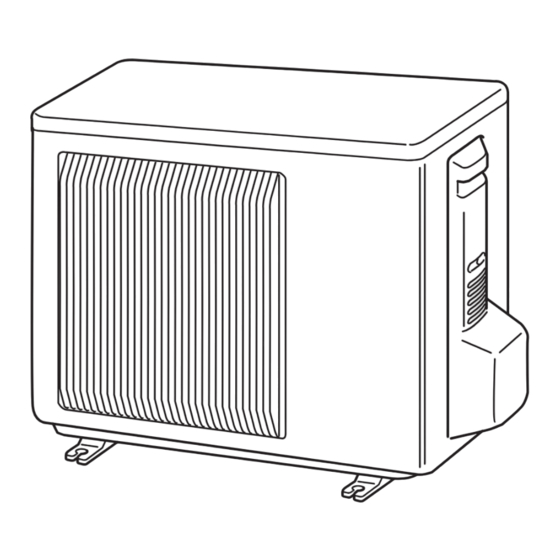
Page 3: Part Names And Functions
PART NAMES AND FUNCTIONS OUTDOOR UNIT MU-GA20VB Air inlet back : MU-GA20VB MU-GA25VB MU-GA25VB MU-GA35VB back and side : MU-GA35VB Piping Drain hose Air outlet Drain outlet SPECIFICATION Outdoor model MU-GA20VB - MU-GA20VB - Single phase Single phase Outdoor unit power supply 230V,50Hz 230V,50Hz Capacity... - Page 4 Outdoor model MU-GA25VB - MU-GA25VB - MU-GA35VB - Single phase Single phase Single phase Outdoor unit power supply 230V,50Hz 230V,50Hz 230V,50Hz Capacity 3.45 Dehumidification Outdoor air flow K /h 1,800 1,800 1,902 Power outlet Running current 3.40 3.40 5.02 Power input 1,120 Auxiliary heater A(kW)
-
Page 5: Noise Criteria Curves
NOISE CRITERIA CURVES MU-GA35VB MU-GA20VB SPL(dB LINE FUNCTION FUNCTION SPL(dB LINE MU-GA25VB COOL COOL Test conditions, Test conditions, Cooling :DB35: WB24: Cooling : DB27: WB19: NC-70 NC-70 NC-60 NC-60 NC-50 NC-50 NC-40 NC-40 NC-30 NC-30 APPROXIMATE APPROXIMATE THRESHOLD OF THRESHOLD OF HEARING FOR HEARING FOR NC-20... -
Page 6: Outlines And Dimensions
OUTLINES AND DIMENSIONS MU-GA20VB MU-GA25VB MU-GA35VB Unit: mm OUTDOOR UNIT REQUIRED SPACE Basically open 100mm or more without any obstruction in front and on both sides of the unit. Drain hole [42 Air in Air in (MU-GA35VB) Open two sides of left, 2 holes 10X21 right, or rear side. -
Page 7: Refrigerant System Diagram
MU-GA35VB OUTDOOR UNIT DSAR CIRCUIT BREAKER NAME SYMBOL SYMBOL NAME SYMBOL NAME COMPRESSOR CAPACITOR COMPRESSOR OVERLOAD RELAY OUTDOOR FAN CAPACITOR OUTDOOR FAN MOTOR (INNER FUSE) COMPRESSOR CONTACTOR DSAR SURGE ABSORBER TERMINAL BLOCK FUSE (T20AL250V) TERMINAL BLOCK NOTE:1. About the indoor side electric wiring refer to the indoor unit electric wiring diagram for servicing. 2. -
Page 8: Performance Curves
MAX. REFRIGERANT PIPING LENGTH Refrigerant piping : m Piping size O.D : mm Length of connecting pipe : m Max. length Max. height Model Outdoor unit Liquid Indoor unit MU-GA20VB MU-GA25VB Gas 0 Gas 0.43 9.52 6.35 Liquid 0 Liquid 0.5 MU-GA35VB MAX. - Page 9 INDOOR UNIT OUTDOOR UNIT Wet-and dry-bulb Wet-and dry-bulb thermometers thermometers 8-1.CAPACITY AND THE INPUT CURVES 11.0 10.0 8-2.OUTDOOR LOW PRESSURE AND OUTDOOR UNIT CURRENT COOL operation Both indoor and outdoor unit are under the same temperature/humidity condition. Relative humidity(%) Dry-bulb temperature Air flow should be set at MAX.
- Page 10 MU-GA25VB MU-GA25VB (kgf/F[Gauge])(MPa[Gauge]) 230V 230V 35(:) 35 (:) 70(%) 70 (%) Ambient temperature(˚C) Ambient humidity(%) Ambient temperature(˚C) Ambient humidity(%) MU-GA35VB MU-GA35VB (kgf/F[Gauge])(MPa[Gauge]) 230V 230V 35(:) 35 (:) 70 (%) 70(%) Ambient temperature(˚C) Ambient humidity(%) Ambient temperature(˚C) Ambient humidity(%)
- Page 11 PERFORMANCE DATA COOL operation (230V) MSC-GA20VB : MU-GA20VB CAPACITY : 2.3(kW) SHF : 0.74 INPUT : 715(W) OUTDOOR DB(:) INDOOR INDOOR DB(:) WB(:) SHC SHF INPUT SHC SHF INPUT SHC SHF INPUT SHC SHF INPUT 2.70 1.51 0.56 2.59 1.45 0.56 2.48 1.39 0.56 2.39 1.34 0.56 2.82 1.24 0.44...
- Page 12 PERFORMANCE DATA COOL operation (230V) MSC-GA20VB : MU-GA20VB CAPACITY : 2.3(kW) SHF : 0.74 INPUT : 715(W) OUTDOOR DB(:) INDOOR INDOOR SHC SHF INPUT SHC SHF INPUT SHC SHF INPUT DB(:) WB(:) 2.25 1.26 0.56 2.07 1.16 0.56 1.99 1.11 0.56 2.37 1.04 0.44 2.21 0.97 0.44 2.13 0.94 0.44...
- Page 13 PERFORMANCE DATA COOL operation (230V) MSC-GA25VB : MU-GA25VB CAPACITY : 2.5(kW) SHF : 0.70 INPUT : 775(W) OUTDOOR DB(:) INDOOR INDOOR DB(:) WB(:) SHC SHF INPUT SHC SHF INPUT SHC SHF INPUT SHC SHF INPUT 2.94 1.53 0.52 2.81 1.46 0.52 2.70 1.40 0.52 2.60 1.35 0.52 3.06 1.23 0.40...
- Page 14 PERFORMANCE DATA COOL operation (230V) MSC-GA25VB : MU-GA25VB CAPACITY : 2.5(kW) SHF : 0.70 INPUT : 775(W) OUTDOOR DB(:) INDOOR INDOOR DB(:) WB(:) SHC SHF INPUT SHC SHF INPUT SHC SHF INPUT 2.45 1.27 0.52 2.25 1.17 0.52 2.16 1.12 0.52 2.58 1.03 0.40 2.40 0.96 0.40 2.31 0.93 0.40...
- Page 15 PERFORMANCE DATA COOL operation (230V) MSC-GA35VB : MU-GA35VB CAPACITY : 3.45(kW) SHF : 0.66 INPUT : 1120(W) OUTDOOR DB(:) INDOOR INDOOR SHC SHF INPUT SHC SHF INPUT SHC SHF INPUT SHC SHF INPUT DB(:) WB(:) 4.05 1.95 0.48 3.88 1.86 0.48 3.73 1.79 0.48 3.59 1.72 0.48 1030...
- Page 16 PERFORMANCE DATA COOL operation (230V) MSC-GA35VB : MU-GA35VB CAPACITY : 3.45(kW) SHF : 0.66 INPUT : 1120(W) OUTDOOR DB(:) INDOOR INDOOR DB(:) WB(:) SHC SHF INPUT SHC SHF INPUT SHC SHF INPUT 3.38 1.62 0.48 1098 3.11 1.49 0.48 1165 2.98 1.43 0.48 1187 3.55 1.28 0.36...
-
Page 17: Troubleshooting
TROUBLESHOOTING MU-GA20VB MU-GA25VB MU-GA35VB 9-1. Cautions on troubleshooting 1. Before troubleshooting, check the following: 1) Check the power supply voltage. 2) Check the indoor/outdoor connecting wire for mis-wiring. 2. Take care the following during servicing. 1) Before servicing the air conditioner, be sure to turn off the main unit first with the remote controller, and then after confirming the horizontal vane is closed, turn off the breaker and/ or disconnect the power plug. - Page 18 9-2. Instruction of troubleshooting MU-GA20VB MU-GA25VB MU-GA35VB Start Indoor unit OPERATION Indoor unit Indoor unit operates. INDICATOR operates. doesn't receive Outdoor unit lamp on the Outdoor unit the signal from doesn't operate indoor unit is doesn't remote controller. normally. flashing on operate.
- Page 19 9-3. Trouble criterion of main parts MU-GA20VB MU-GA25VB MU-GA35VB Figure Part name Check method and criterion Compressor MU-GA20/GA25VB (MC) INNER PROTECTOR Measure the resistance between the terminals with a tester. AUX. MAIN MU-GA20/ (Coil wiring temperature –10°C ~ 40°C) GA25VB- 150i 5°C OPEN Normal 90i10°C CLOSE...
-
Page 20: Disassembly Instructions
DISASSEMBLY INSTRUCTIONS <"Terminal with locking mechanism" Detaching points> The terminal which has the locking mechanism can be detached as shown below. There are two types ( Refer to (1) and (2)) of the terminal with locking mechanism. The terminal without locking mechanism can be detached by pulling it out. Check the shape of the terminal before detaching. - Page 21 OPERATING PROCEDURE PHOTOS 2. Removing the electrical parts Photo 4 (1) Remove the service panel and the cabinet.(Refer to 1.) Compressor Compressor Terminal (2) Remove the following parts. capacitor (C1) contactor (52C) block(TB2) • Compressor capacitor (C1) • Outdoor fan capacitor (C2) •...
-
Page 22: Parts List
PARTS LIST (non-RoHS compliant) MU-GA20VB MU-GA25VB MU-GA35VB 11-1. OUTDOOR UNIT STRUCTURAL PARTS, ELECTRICAL PARTS AND FUNCTIONAL PARTS This figure shows MU-GA20/GA25VB. - Page 23 PARTS LIST (non-RoHS compliant) MU-GA20VB MU-GA25VB MU-GA35VB 11-1. OUTDOOR UNIT STRUCTURAL PARTS, ELECTRICAL PARTS AND FUNCTIONAL PARTS Part numbers that are circled are not shown in the illustration. Q'ty/unit Symbol in Wiring Part No. Remarks Part name MU-GA20VB- MU-GA25VB- MU-GA35VB- Diagram E02 901 630 OUTDOOR HEAT EXCHANGER...
-
Page 24: Rohs Parts List
RoHS PARTS LIST (RoHS compliant) MU-GA20VB MU-GA25VB MU-GA35VB 12-1. OUTDOOR UNIT STRUCTURAL PARTS, ELECTRICAL PARTS AND FUNCTIONAL PARTS This figure shows MU-GA20/GA25VB. - Page 25 RoHS PARTS LIST (RoHS compliant) MU-GA20VB MU-GA25VB MU-GA35VB 12-1. OUTDOOR UNIT STRUCTURAL PARTS, ELECTRICAL PARTS AND FUNCTIONAL PARTS Part numbers that are circled are not shown in the illustration. Q'ty/unit Symbol Part No. in Wiring Part name Remarks GA20VB- GA20VB- GA25VB- GA25VB- GA35VB-...
- Page 28 HEAD OFFICE: TOKYO BLDG.,2-7-3, MARUNOUCHI, CHIYODA-KU, TOKYO100-8310, JAPAN C C Copyright 2005 MITSUBISHI ELECTRIC ENGINEERING CO.,LTD Distributed in May 2006. No.OB386 REVISED EDITION-B 6 Distributed in Mar. 2005. No.OB386 REVISED EDITION-A 6 New publication, effective May 2006 Distributed in Jan. 2005. No.OB386 6 Specifications subject to change without notice.