Table of Contents
Advertisement
Advertisement
Table of Contents

Related Manuals for Focusrite ISA TWO


Summary of Contents for Focusrite ISA TWO
- Page 1 User Guide Mode d’emploi Bedienungsanleitung www.focusrite.com FA0540-01...
-
Page 2: Important Safety Instructions
IMPORTANT SAFETY INSTRUCTIONS Read these instructions. Keep these instructions. Heed all warnings. Follow all instructions. Do not use this apparatus with water. Clean only with dry cloth. Install in accordance with the manufacturer’s instructions. Do not install near any heat sources such as radiators, heat registers, stoves, or other apparatus (including amplifiers) that produce heat. Do not defeat the safety purpose of the polarized or grounding-type plug. A polarized plug has two blades with one wider than the other. A grounding type plug has two blades and a third grounding prong. The wide blade or the third prong are provided for your safety. If the provided plug does not fit into your outlet, consult an electrician for replacement of the obsolete outlet. 10. Protect the power cord from being walked on or pinched particularly at plugs, convenience receptacles, and the point where they exit from the apparatus. 11. Only use attachments/accessories specified by the manufacturer. 12. Use only with the cart, stand, tripod, bracket, or table specified by the manufacturer, or sold with the apparatus. When a cart is used, use caution when moving the cart/apparatus combination to avoid injury from tip-over. 13. Unplug this apparatus during lightning storms or when unused for long periods of time. 14. Refer all servicing to qualified service personnel. Servicing is required when the apparatus has been damaged in any way, such as power-supply cord or plug is damaged, liquid has been spilled or objects have fallen into the apparatus, the apparatus has been exposed to rain or moisture, does not operate normally, or has been dropped. 15. No naked flames, such as lighted candles, should be placed on the apparatus. WARNING: To reduce the risk of fire or electric shock, do not expose this apparatus to rain or moisture. It is important that the apparatus shall not be exposed to dripping or splashing and that no objects filled with liquids, such as vases shall be placed on the apparatus. • Do not expose this apparatus to drips or splashes. • Do not place any objects filled with liquids, such as vases, on the apparatus. • Do not install this apparatus in a confined space such as a bookcase or similar unit. - Page 3 ENVIRONMENTAL DECLARATION Compliance Information Statement: Declaration of Compliance procedure Product Identification: Focusrite ISA Two Responsible party: American Music and Sound Address: 5304 Derry Avenue #C Agoura Hills, CA 91301 Telephone: 800-994-4984 This device complies with part 15 of the FCC Rules. Operation is subject to the following two conditions: (1) This device may not cause harmful interference, and (2) this device must accept any interference received, including interference that may cause undesired operation. For USA To the User: 1. Do not modify this unit! This product, when installed as indicated in the instructions contained in this manual, meets FCC requirements. Modifications not expressly approved by Focusrite may void your...
-
Page 4: Table Of Contents
TABLE OF CONTENTS IMPORTANT SAFETY INSTRUCTIONS . . . . . . . . . . . . . . . . . . . . . . . . . . . . . . . . . . . . . . . . . . . . . . 2 TABLE OF CONTENTS . -
Page 5: Overview
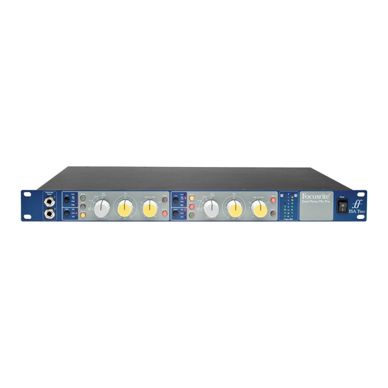
OVERVIEW Introduction The ISA Two provides two of Focusrite’s prestigious transformer-based microphone preamps. It features the same classic circuitry and renowned audio quality found in the original at a new level of affordability. With selectable input impedance, direct instrument inputs and insert points, the ISA Two creates the perfect front end for the discerning recording professional. First introduced in 1985, the ISA microphone preamp holds a reputation for outstanding transparency along with subtle warmth contributed by transformer core saturation. The addition of a variable impedance circuit allows ISA users to perfectly match the preamp with any microphone, or to use different settings creatively to shape the sound of the microphone. Unchanged for decades, the ISA microphone preamp topology offers incredible clarity and the signature Focusrite sound that makes it the top choice among many audio professionals today. Features • Two ISA series transformer-based preamps •... -
Page 6: Getting Started And Powering Up
GETTING STARTED AND POWERING UP The ISA Two is a high quality two-channel preamplifier, which can be used to record microphone, line-level and instrument sources. Microphones and line-level sources are connected at the rear panel, whilst instruments are plugged directly into the front panel. The front panel also has gain controls and other controls such as phantom power and input impedance selection. LED peak meters are provided, with a calibration control at the rear panel, to ensure a suitable signal level is achieved. An on-off switch on the front panel applies power to the unit, providing the supplied IEC mains lead is connected to the socket on the rear. Please make sure that the ISA Two is turned on before powering any devices connected to the outputs. The IEC mains lead supplied with the unit should have the correct moulded plug for your country. The wiring colour code used is: Live Neutral Earth For units shipped to the USA, Canada, Taiwan and Japan: Black White Green For units shipped to any other country: Brown Blue Green and Yellow... -
Page 7: Hardware Features
HARDWARE FEATURES Front Panel 1. Input switch: selects the input source (mic, line or instrument) 2. Gain control: sets the gain of the input signal in stepped values of 10 dB 3. 30-60 switch: selects the range of the Gain control (0 to +30 dB, or +30 to +60 dB). The default range is 0 to +30 dB 4. Trim control: allows an additional 20 dB of gain to be applied to a mic/line-level signal, or can be used as a gain control for the Instrument Inputs 5. Phantom power switch: supplies +48 V to the corresponding mic input on the rear panel 6. Z In switch: sets the mic input impedance to 600 Ω (Low), 1.4 kΩ (ISA 110), 2.4 kΩ (Med) or 6.8 kΩ (High) 7. Phase switch: inverts the phase of the signal 8. Filter switch: activates a high pass filter (HPF) 9. Filter control: selects the frequency of the high pass filter between 16 Hz-420 Hz 10. Insert: allows the signal to be sent to additional external processors (via the send and return connectors on the rear panel) prior to the output 11. Peak LED meters: show the main output levels in dBFS 12. Instrument Inputs: for connecting high impedance instruments such as guitars Front Panel Sections Input (1) Pressing Input steps through each of the three inputs, as indicated by the corresponding LEDs. When the Mic LED is lit, the microphone input is active. An XLR input for a microphone, as well as 3-pole (TRS) ¼” inputs for line-level sources, can be found on the rear panel. A 2-pole (TS) ¼” input for an instrument (DI) is available on the front panel. - Page 8 Mode 1: Mic Gain Range 0-30 With the 30-60 switch (3) off, the stepped Gain control operates over a gain range of 0 dB to +30 dB, the gain setting being indicated on the front panel by the outer arc of numbers around the Gain control. Mode 2: Mic Gain Range 30-60 With the 30-60 switch (3) on (illuminated), the stepped gain dial operates over a gain range of +30 dB to +60 dB, the gain setting being indicated on the front panel by the outer arc of numbers around the gain knob. An additional 20 dB of gain can be applied to the signal after the mic/line stepped gain control using the Trim control (4). (See Trim control text below for a full explanation). Line Input Gain (2) With the line input selected, the user has access to gain settings from –20 dB to +10 dB in 10 dB steps, indicated on the front panel by the inner arc of numbers around the stepped gain knob. The 30-60 switch (3) is inactive when the line input is selected. An additional 20 dB of gain can be applied to the signal after the stepped mic/line gain using the Trim control (4). (See the Trim control text below for a full explanation.) Trim - Mic or Line Modes (4) The Trim control provides additional gain of up to +20 dB when mic or line inputs are selected. The level of trim chosen is indicated on the front panel by the inner arc of numbers around the trim knob. The additional 20 dB of gain that can be applied to the mic or line signal is very useful for two reasons: •...
- Page 9 Z In - Input Impedance (6) Pressing the Z In switch steps through each of the four transformer preamp input impedance values, as indicated by the corresponding LEDs. By selecting different values for the impedance of the ISA Two transformer input (mic or line), the performance of both the ISA Two preamp and the microphone connected can be tailored to set the desired level and frequency response. The impedance values are as follows: • Low – 600 Ω • ISA 110 – 1.4 kΩ • Med – 2.4 kΩ • High – 6.8 kΩ Phase (7) Pressing the Phase switch (illuminated when active) inverts the phase of the selected input to correct phase problems when using multiple microphones, or when incorrect wiring polarity has occurred. Filter (8) Pressing the Filter switch (illuminated when active) makes the high pass filter active in the audio path. This is useful for removing any unwanted bass caused by proximity effect or rumble. High Pass Filter Control (9) The high pass filter is adjustable between 16 Hz and 420 Hz, with an 18 dB/octave roll-off. Insert (10) Pressing the Insert switch (illuminated when active) routes the insert return socket to the output instead of the direct mic, line or instrument signal. The input signal is permanently routed to the insert send output on the rear panel. Insert allows the input signal to be routed to other hardware for processing before returning back into the ISA Two.
-
Page 10: Rear Panel
Rear Panel 1. MIC INPUT (female XLR) 2. LINE INPUT (3-pole ¼”- TRS) 3. Insert SEND: sends the main mic/line/inst input for additional signal processing (3-pole ¼”- TRS) 4. Insert RETURN: for externally processed signals - the Insert switch (10) on the front panel should be active when in use (3-pole ¼”- TRS) 5. OUTPUT: the main mic/line/inst input signal, or the return signal when active, as selected by the input switch on the front panel (male XLR) 6. PEAK METER CALIBRATION: allows calibration of the peak meters (see Metering for details) 7. Mains IEC connector Rear Panel Sections Analogue Inputs The MIC INPUT and LINE INPUT can be used to connect an analogue source to the ISA Two. Phantom power can be applied to the MIC INPUT connector by enabling the +48V switch. Note that phantom power can be applied to the connector whether or not a microphone is connected, and is not recalled after a power cycle. If you are unsure whether your microphone requires phantom power, refer to its handbook. It is possible to damage some microphones (most notably ribbon microphones) by providing phantom power to them. - Page 11 Setting a Microphone Level To record a microphone signal using the ISA Two: 1. Using an XLR cable connect the microphone to one of the MIC INPUTS on the rear panel. 2. Select Mic as the input source using the Input switch. 3. If required, activate phantom power using the +48V switch. If you are unsure whether your microphone requires phantom power, refer to its handbook. It is possible to damage some microphones (most notably ribbon microphones) by providing phantom power to them. 4. Set the gain of the microphone using the Gain and Trim controls on the front panel while observing the LED meter. The stepped gain sets the level in 10 dB steps, with Trim providing a further 20 dB. If the level is too low, use the 30-60 switch to increase the gain range. 5. Use the Z In switch to adjust the input impedance (see “Mic Preamp Input Impedance” on page 12 for details). 6. Activate the Phase and Filter switches if required. 7. The microphone signal will then be sent to the corresponding rear panel OUTPUT connector. Setting a Line-level Signal To record a line-level signal with the ISA Two: 1. Connect the line-level signal, using a ¼” 3-pole TRS jack cable, to one of the rear panel LINE...
-
Page 12: Applications
(e.g., making a preamp input impedance 200 Ω to match a 200 Ω microphone) still reduces the microphone output and signal-to- noise ratio by 6 dB, which is undesirable. To minimise microphone loading, and to maximise signal-to-noise ratio, preamps have traditionally been designed to have an input impedance about ten times greater than the average microphone, around 1.2 kΩ to 2 kΩ. (The original Focusrite ISA 110 preamp design followed this convention and has an input impedance of 1.4 kΩ at 1 kHz.) Input impedance settings greater than 2 kΩ tend to make the frequency-related variations of microphone outputs less significant than at low impedance settings. Therefore high input impedance settings yield a microphone performance that is flatter in the low and mid frequency areas and boosted in the high frequency area when compared to low impedance settings. - Page 13 voltage it can generate into a signal capable of being amplified by a mic preamp. The ribbon microphone output transformer typically has a ratio of around 1:30 (primary: secondary) to increase the ribbon voltage to a useful level, and this transformer ratio also has the effect of increasing the output impedance of the mic to around 200 Ω at 1 kHz. This transformer impedance, however, varies greatly with frequency - it can almost double at some frequencies (known as the resonance point) and tends to roll off to very small values at low and high frequencies. Therefore, as with the dynamic and condenser microphones, the mic preamp input impedance has an effect on the signal levels and frequency response of the ribbon microphone output transformer, and thus the ‘sound quality’ of the microphone. It is recommended that a mic preamp connected to a ribbon microphone should have an input impedance of at least 5 times the nominal microphone impedance. For a ribbon microphone impedance of 30 Ω to 120 Ω, the input impedance of 600 Ω (Low) will work fine. For 120 Ω to 200 Ω ribbon microphones, the input impedance setting of 1.4 kΩ (ISA 110) is recommended.
-
Page 14: Example Of Usage
EXAMPLE OF USAGE Recording an analogue vocal signal to a DAW... -
Page 15: Specifications
SPECIFICATIONS Performance Specifications Maximum Input and Output Levels +24 dBu with a THD+N < 0.01% at 1kHz measured with 0 dBu input Maximum Output Level level, with 150 Ω source impedance and 22Hz/22kHz band-pass filter Maximum Microphone +7 dBu with a THD+N < 0.7% at 1kHz measured at 0 dB of gain with Transformer Input Level 150 Ω source impedance and 22Hz/22kHz band-pass filter Mic Input Response 0 dB to +60 dB in 10 dB steps, plus 0 dB to +20 dB continuously Gain range variable trim Low = 600 Ω Switched Impedance setting ISA 110 = 1.4 kΩ Input Impedance Equivalent Input Impedance at 1 kHz Med = 2.4 kΩ High = 6.8 kΩ Measured at 60 dB of gain with 150 Ω EIN source impedance and 22 Hz-22 kHz -127 dB (Equivalent Input Noise) band pass filter Noise at output with unity gain (0 dB) Noise -97 dBu and 22 Hz-22 kHz band pass filter Measured with 150 Ω source impedance 121 dB relative to max Signal-to-Noise Ratio and 22 Hz-22 kHz band pass filter... - Page 16 -0.5 dB at 10 Hz, At minimum gain (0 dB) -1 dB at 135 kHz, relative to 1 kHz Frequency Response -6 dB at 10 Hz, At maximum gain (+60 dB) -1 dB at 115 kHz, relative to 1 kHz CMRR (Common Mode -94 dB for mic input at 60 Hz for max. output = +24 dBu Rejection Ratio) -91 dB for mic input at 10 kHz for max. output = +24 dBu Crosstalk Channel to Mic input, with I/P = 0 dBu, gain = 0 dB @ 1 kHz input to channel A, Channel channel B output = -85 dB Line Input Response -20 dB to +10 dB in 10 dB steps, plus 0 dB to +20 dB continuously Gain Range variable trim Input Impedance 10 kΩ from 10 Hz to 200 kHz Noise at main output with gain at unity (0 dB) measured with 50 Ω source Noise -97 dBu impedance and a 22Hz - 22 kHz band pass filter Measured with 50 Ω source impedance 121 dB relative to max Signal-to-Noise Ratio and a 22 Hz-22 kHz band pass filter output +24 dBu Measured with a 0 dBu input signal, Total Harmonic Distortion < 0.002% at 1 kHz +10 dB of gain and a 22 Hz-22 kHz band + Noise pass filter...
-
Page 17: Physical And Electrical Characteristics
Instrument Input Response Gain Range +10 dB to +40 dB continuously variable trim > 2 MΩ Input Impedance Measured with 22 Hz-22 kHz Noise Minimum gain (+10 dB) = -95 dBu band pass filter -0.1 dB at 10 Hz, At minimum gain (+10 dB) -1 dB at 115 kHz, relative to 1 kHz Frequency Response -2.5 dB at 10 Hz, At maximum gain (+40 dB) -1 dB at 110 kHz, relative to 1 kHz High Pass Filter Roll-Off 18 dB per octave (3 pole filter) Frequency Range Continuously variable from 16 Hz to 420 Hz (-3 dB) Physical and Electrical Characteristics Weight and Dimensions W x D x H 480 mm x 280 mm x 44 mm Weight 3.7 kg... -
Page 18: Warranty
WARRANTY All Focusrite products are covered by a warranty against manufacturing defects in material or craftsmanship for a period of one year from the date of purchase. Focusrite in the UK, or its authorised distributors worldwide, will do their best to ensure that any fault is remedied as quickly as possible. This warranty is in addition to your statutory rights. This warranty does not cover any of the following: Carriage to and from the dealer or factory for inspection or repair Labour charge if repaired other than by the distributor in the country of purchase or Focusrite in the UK Consequential loss or damage, direct or indirect, of any kind, however caused Any damage or faults caused by abuse, negligence, improper operation, storage or maintenance If a product is faulty, please first contact the dealer from which the product was purchased. If the...