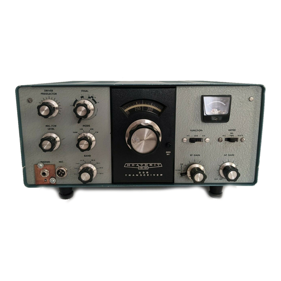
Heathkit HW-101 Optimization Manual
Hide thumbs
Also See for HW-101:
- User manual (246 pages) ,
- Troubleshooting manual (190 pages) ,
- Assembly and operation manual (19 pages)
Advertisement
Quick Links
Download this manual
See also:
User Manual
Optimizing the Heathkit HW-101,
SB100-102 Transceivers
T
T
he Heathkit HW/SB series of transceivers were very popular in the late 60's through
70's and are fairly plentiful on the used market even today, nearly 30 years later.
This series of modifications will increase the audio quality of both receive and transmit,
improve operation on CW, enhance strong signal handling of the rigs, and make the units
useable with the low-Z headphones so often used today. All of these changes require no
hole drilling or mechanical changes at all, and the rig can be easily restored to its original
configuration at anytime if desired. The text deals with the HW-101, but the changes are
applicable to the above mentioned SB-series as well.
Conversion to Low-Z Headphones:
These rigs are designed to be used with Hi-Z headphones, but if low-Z phones are used
the outboard speaker will not mute completely with the phones connected. To convert to
low-Z phones, make the following wiring changes referring to (Figure 1) of this
document, and pictorial 8-4 (foldout from page 53), and pictorial 8-5 (foldout from page
67) of the HW-101 manual:
1.) Remove the black wire from terminal strip BA lug 2 and reconnect it to lug 3
(ground).
2.) Remove the green wire and the 100Ω resistor from jack AB (speaker).
3.) Connect the green wire to terminal strip BA lug 2.
4.) Connect the 100Ω resistor removed in step 2 to lugs 2 and 3 of terminal strip BA.
5.) Remove the jumper wire from lugs 1 and 2 of headphone jack L.
6.) Run a NEW wire along the wiring harness from speaker jack AB lug 1 to the
headphone jack lug 2.
Now the external speaker should mute completely when low-Z phones are used.
1
Advertisement

Related Manuals for Heathkit HW-101


Summary of Contents for Heathkit HW-101
- Page 1 The text deals with the HW-101, but the changes are applicable to the above mentioned SB-series as well.
- Page 2 Figure 1 Improved CW Operation: In the CW mode the rig’s relays are energized by the CW sidetone amplifier's sidetone output driving the vox relay amplifier. The audio (sidetone) drive to the vox amp is a bit on the low side for fast relay action, and at speeds approaching 20 wpm the first dot sent is heard in the sidetone but isn’t transmitted due to the slow relay response time.
- Page 3 1) Connect a .001 µfd disk capacitor (DO NOT use a higher value) from relay RL1 pin 1, to ground (Figure 1). 2) Connect a piece of wire about 8” long from pin 1 of RL1 and run this wire through the same opening in the shield as the wiring harness.
- Page 4 Transmit Improvements: The transmitter audio quality can be improved by changing the value of coupling capacitor C11 on the modulator board from .001 µfd to .01 µfd (Figure 4). This will increase the low frequency response and give the transmit audio a little more “body”. If 10KΩ...
- Page 5 Receive Improvements: The receiver’s strong signal-handling capability and audio quality can be vastly improved by the following changes: During alignment check to see if, while adjusting T-102 (Figure 3), there are two points where the transformer can be peaked -- one spot for transmit and a slightly different setting for receive.
- Page 6 Figure 4 Additional rolloff of the high frequency response will remove the raspy nature of the receive audio, and this is accomplished by changing the value of capacitor C119 on the I.F. board from 500pf to .001 µfd (Figure 3). The low-end audio response of the audio amplifier increases slightly by replacing coupling capacitor C306 on the audio board with a .01 µfd disk capacitor (Figure 2).
- Page 7 Figure 5 I.F. Filter Passband Improvements: I believe the crystals that Heath supplied for the carrier oscillator were of fairly wide tolerance, thus the frequencies of the LSB/USB/CW carrier injection may not be properly positioned on the slope of the I.F. filter. This can affect both the receive and transmit audio response to a great degree.
- Page 8 10 pf connected in parallel with the crystal. On my HW-101 I put the capacitors (silver mica’s) directly on the circuit board foils. I got one sideband to sound the way I liked, and then simply adjusted the other sideband to match it in audio response.
- Page 9 After all the above mentioned changes are made, give the rig a touch up alignment and enjoy a much improved vintage rig! Many thanks to Lenny WB8JCJ for his help in editing, image scanning, input, and implementation of these changes into his HW-101. His help was indispensable.