
Related Manuals for Ariens 902032


Summary of Contents for Ariens 902032
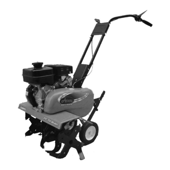
- Page 1 FRONT TINE TILLER Owners Manual Models 902032 24" FRONT TINE TILLER ENGLISH 21547014 423442 Rev 1 02.10.09 Printed in USA...
-
Page 2: Safety Rules
Safe Operation Practices for Walk-Behind Powered Ro ta ry Tillers TRAINING • Read the Owner’s Manual care ful ly. Be thor ough ly fa mil iar with the controls and the proper use of the equip ment. Know how to stop the unit and disengage the controls quickly. -
Page 3: Table Of Contents
PRODUCT SPECIFICATIONS Gasoline Capacity: 3.6 Quarts (3.4L) Unleaded Regular Oil (API-SG-SL): SAE 10w-30(Above 32°F/0°C) (Capacity: 20 oz./0.6L) SAE 5w-30(Below 32°F/0°C) Spark Plug: NGK BR-5HS (Champion RL86C) (Gap: .030"/0.76mm) CONGRATULATIONS on your purchase of a new tiller. It has been designed, en gi neered and manu fac tured to give you the best pos sible de penda bil ity and per form ance. -
Page 4: Assembly
ASSEMBLY Your new tiller has been assembled at the factory with exception of those parts left unassembled for shipping purposes. To ensure safe and proper operation of your tiller all parts and hardware you assemble must be tightened securely. Use the correct tools as necessary ensure proper tightness. -
Page 5: Assembly
UNPACK CARTON & INSTALL HANDLE (See Fig. 2) CAUTION: Be careful of exposed sta ples when handling or disposing of cartoning material. IMPORTANT: WHEN UNPACKING AND AS SEM BLING TILLER, BE CAREFUL NOT TO STRETCH OR KINK CABLE(S). • Cut cable ties securing handles. •... -
Page 6: Operation
KNOW YOUR TILLER READ THIS MANUAL AND SAFETY RULES BEFORE OPERATING YOUR TILLER. Compare the illustrations with your tiller to familiarize yourself with the location of various controls and adjustments. Save this manual for future reference. These symbols may appear on your Tiller or in literature supplied with the product. Learn and understand their meaning. FORWARD TINE CONTROL THROTTLE CONTROL FUEL VALVE... - Page 7 The operation of any tiller can result in foreign objects thrown into the eyes, which can result in severe eye damage. Always wear safety glasses or eye shields before starting your tiller and while tilling. We recommend a wide vision safety mask for over spectacles or standard safety glasses.
- Page 8 TO TRANSPORT CAUTION: Before lifting or trans port ing, allow tiller engine and muffler to cool. Disconnect spark plug wire. gasoline from fuel tank. AROUND THE YARD • Tip depth stake forward until it is held by the stake spring. •...
-
Page 9: Operation
6. After starting the engine, gradually open choke by turning the choke lever and finally keep it fully opened. Do not fully open the choke lever immediately when the engine is cold or the ambient temperature is low, because the engine may stop. NOTE: If engine does not start, see trou ble shoot ing points. -
Page 10: Maintenance Schedule
GENERAL RECOMMENDATIONS The warranty on this tiller does not cover items that have been subjected to operator abuse or negligence. To receive full value from the warranty, the operator must main tain tiller as instructed in this manual. Some adjustments will need to be made periodically to properly maintain your tiller. - Page 11 Disconnect spark plug wire before performing any maintenance (except car bu re tor adjustment) to prevent accidental start ing of engine. Prevent fires! Keep the engine free of grass, leaves, spilled oil, or fuel. Re move fuel from tank before tipping unit for maintenance. Clean muffler area of all grass, dirt, and debris. Do not touch hot muffler or cylinder fins as contact may cause burns.
-
Page 12: Maintenance
COOLING SYSTEM (See Fig. 14) Your engine is air cooled. For proper en gine performance and long life keep your engine clean. • Clean air screen frequently using a stiff-bristled brush. • Remove blower housing and clean as nec es sary. •... -
Page 13: Service & Adjustments
SERVICE AND ADJUSTMENTS CAUTION: Disconnect spark plug wire from spark plug and place wire where it cannot come into contact with plug. TILLER TO ADJUST HANDLE HEIGHT (See Fig. 15) Factory assembly has provided lowest handle height. Se lect handle height best suited for your tilling conditions. Handle height will be different when tiller digs into soil. -
Page 14: Service And Adjustments
SERVICE AND ADJUSTMENTS TINE OPERATION CHECK (See Fig.19) WARNING: Disconnect spark plug wire from spark plug to prevent starting while checking tine operation. For proper tine operation, tine control lever must be against control body and all slack removed from inner wire of control cable when control is in the “OFF”... -
Page 15: Service & Adjustments
SERVICE AND ADJUSTMENTS BELT REPLACEMENT • Install new V-belt to engine pulley first then to trans mis- sion pulley. Ensure belt is positioned on inside groove of both pulleys, inside all belt guides and rests on idler pulley. CHECK TINE OPERATION •... -
Page 16: Storage
Immediately prepare your tiller for storage at the end of the season or if the unit will not be used for 30 days or more. WARNING: Never store the tiller with gasoline in the tank inside a build ing where fumes may reach an open flame or spark. -
Page 17: Troubleshooting
TROUBLESHOOTING POINTS PROBLEM CAUSE Will not start Out of fuel. Engine not “CHOKED” properly. Engine flooded. Dirty air cleaner. Water in fuel. Clogged fuel tank. Loose spark plug wire. Bad spark plug or improper gap. Carburetor out of adjustment. Hard to start Throttle control not set properly. -
Page 18: Parts
FRONT TINE TILLER – MODEL NUMBER 90203200 (MFG. ID. NO. 96086000100) HANDLE ASSEMBLY... - Page 19 HANDLE ASSEMBLY ITEM MFG. NOTE: All component dimensions are given in U.S. inches. ARIENS PART NO. DESCRIPTION 137176 21546089 Bracket, Handle 72140512 21546771 Bolt, Carriage 5/16-18 x 1-1/2 165787 21546171 Grip, Handle 166376 21546175 Handle, L.H. 73680500 21546784 Nut, Hex, Crownlock 5/16-18...
- Page 20 FRONT TINE TILLER – MODEL NUMBER 90203200 (MFG. ID. NO. 96086000100) BELT GUARD AND PULLEY ASSEMBLY...
- Page 21 BELT GUARD AND PULLEY ASSEMBLY ITEM MFG. NOTE: All component dimensions given in U.S.inches. ARIENS PART NO. DESCRIPTION 23230506 21546545 Screw Set 5/16-18 x 3/8 Patch 130812 21546079 Sheave, Engine 86777 21546830 Screw, Tap Hex Head 74770508 21546813 Bolt, Hex Head 5/16-24 unf x 1/2...
- Page 22 FRONT TINE TILLER – MODEL NUMBER 90203200 (MFG. ID. NO. 96086000100) WHEEL AND DEPTH STAKE ASSEMBLY...
- Page 23 WHEEL AND DEPTH STAKE ASSEMBLY ITEM MFG. NOTE: All component dimensions are given in U.S. inches. ARIENS PART NO. DESCRIPTION 9194R 21546837 Pin, Clevis 74760520 21546806 Bolt, Hex Head 5/16-18 x 1-1/4 74760512 21546804 Bolt, Hex Head 5/16-18 x 3/4...
- Page 24 FRONT TINE TILLER – MODEL NUMBER 90203200 (MFG. ID. NO. 96086000100) TINE ASSEMBLY...
-
Page 25: Tine Assembly
TINE ASSEMBLY ITEM MFG. NOTE: All component dimensions are given in U.S. inches. ARIENS PART NO. DESCRIPTION 156929 21546140 Tine, Outer, R.H. 3146R 21546548 Retainer, Spring 156924 21546138 Tine, Inner, R.H. 156923 21546137 Tine, Inner, L.H. 156925 21546139 Tine, Outer, L.H. - Page 26 FRONT TINE TILLER – MODEL NUMBER 90203200 (MFG. ID. NO. 96086000100) TRANSMISSION...
- Page 27 TRANSMISSION ITEM MFG. NOTE: All component dimensions are given in U.S. inches. ARIENS PART NO. DESCRIPTION 74760524 21546807 Bolt, Hex Head, Gr. 25/16-18 x 1-1/2 74780652 21546817 Bolt, Hex Head, 3/8-16 x 3-1/4 19131311 21546282 Washer 13/32 x 13/16 x 11 Ga.
- Page 28 FRONT TINE TILLER – MODEL NUMBER 90203200 (MFG. ID. NO. 96086000100) DECALS...
- Page 29 DECALS ITEM MFG. NOTE: All component dimensions are given in U.S. inches. ARIENS PART NO. DESCRIPTION 423719 21546717 Decal, Console 424723 21546734 Decal, Belt Guard 110613X 21546047 Decal, Tine Control 423701 21546713 Decal, Subaru Tine Shield 110614X 21546048 Decal, Hand Placement...
-
Page 30: Warranty
Two-Year Limited Tiller Warranty This warranty statement applies only to Tillers. original purchaser 90-Day Limited Warranty on Service Parts and Accessories Exceptions, Limitations, Exclusions Customer Responsibilities Register the product immediately at the time of sale. original purchaser Exceptions and Limitations... - Page 31 DISCLAIMER OF FURTHER WARRANTY Ariens Company makes no warranty, express or implied, other than what is expressly made in this warranty. If the law of your state provides that an implied warranty of merchantability, or an implied warranty of fitness for particular purpose, or any other implied warranty, applies to Ariens Company, then any such implied warranty is limited to the duration of this warranty.
-
Page 32: Parts And Service
For parts and service, contact your local Ariens dealer. To find a dealer in your area, call 1-800-317-5898, or use the Dealer Locator on our web site, www.ariens.com.