Table of Contents
Advertisement
Advertisement
Table of Contents

Related Manuals for Ryobi RDP102L


Summary of Contents for Ryobi RDP102L
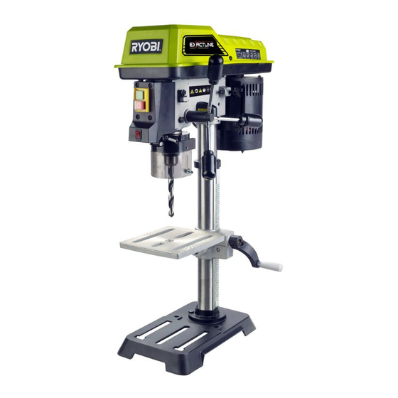
- Page 1 RDP102L 254MM (10”) DRILL PRESS WITH LASER OPERATOR’S MANUAL...
- Page 2 DESCRIPTION 1. Head assembly 57. Lower front notch 2. Table 58. Spring cap 3. Base 59. Outer jam nut 4. Rack 60. Inner nut 5. Column assembly 61. Notch 6. Rack ring 62. Boss 7. Feed handles 63. Chuck jaws 8.
- Page 3 4 mm 3 mm Fig.1...
- Page 4 Fig. 2 Fig. 3 Fig. 4 Fig. 5...
- Page 5 Fig. 6 Fig. 9 Fig. 7 Fig. 10 Fig. 8 Fig. 11...
- Page 6 Fig. 12 Fig. 15 Fig. 16 Fig. 13 Fig. 17 Fig. 14...
- Page 7 Fig. 18 Fig. 22 Fig. 19 Fig. 23 Fig. 20 Fig. 24 Fig. 21...
- Page 8 Fig. 24 Fig. 27 DRILLING SPEED TABLE (RPM) Material Drill Bit Diameter Wood Alum., Zinc., Brass Iron, Steel (Inches) 1/16 2430 2430 1800 3/16 2430 1300 1800 5/16 1300 1800 Fig. 25 Fig. 28 Fig. 29 Fig. 26...
- Page 9 Fig. 30 Fig. 31...
- Page 10 Important! It is essential that you read the instructions in this manual before operating this machine. Subject to technical modifications.
-
Page 11: General Power Tool Safety Warnings
or when changing attachments, blades, bits, cutters, GENERAL POWER TOOL SAFETY WARNINGS etc., all tools should be disconnected from power source. WARNING ■ Avoid accidental starting. Be sure switch is off when plugging in any tool. When using electric tools, basic safety precautions should always be followed to reduce the risk of fire, ■... -
Page 12: Special Safety Rules
replace a damaged or worn cord immediately. Stay could contact the drill or other cutting tool if the constantly aware of cord location and keep it well workpiece should unexpectedly shift. away from the rotating blade. ■ Never perform any operation by moving the head ■... -
Page 13: Electrical Connection
exposed wires and cut or worn insulation. SPECIFICATIONS WARNING Product Specifications Keep the extension cord clear of the working area. Net weight 21.2 kg Position the cord so that it will not get caught on lumber, Chuck size 13 mm (1/2") tools or other obstructions while you are working with a power tool. -
Page 14: Carton Contents
CARTON CONTENTS ASSEMBLY AND ADJUSTMENTS UNPACKING AND CHECKING CONTENTS WARNING For your own safety, never connect plug to power WARNING source outlet until all assembly steps are complete and If any part is missing or damaged, do not plug the drill you have read and understood the safety and operating press in until the missing or damaged part is replaced, instructions. - Page 15 INSTALLING THE HEAD REMOVING THE CHUCK 1. Turn the feed handles to lower the chuck to the lowest See Figure 11. position. 2. Place a ball joint separator (not shown) above the WARNING chuck and tap it lightly with a hammer or rubber The Drill Press head is heavy and should be lifted with mallet to cause the chuck to drop from the spindle.
- Page 16 NOTE: A bevel scale has been included to measure NOTE: Do not remove this inner nut, because the approximate bevel angles. If precision is necessary, a spring will forcibly unwind. square or other measuring tool should be used to position 4.
-
Page 17: Operation
damage. Therefore, do not look directly into the laser each of the laser housings with a hex key and rotate beam. the laser adjustment knobs until the lines meet in the centre of the “X”. Retighten the set screws to secure. ■... -
Page 18: Installing And Removing Bits
To turn the drill press off: marked on the workpiece. 1. Press the OFF button ( O ). Depth scale method See Figure 28. WARNING NOTE: With the chuck in the upper position, the tip of the Always make sure the workpiece is not in contact with drill bit must be just slightly above the top of the workpiece. -
Page 19: Tilting The Table
workpiece) so that it contacts the left side of the WARNING column. To prevent the workpiece or backup material from being • Whenever possible, position the workpiece to thrown while drilling, you MUST position the workpiece contact the left side of the column. If it is too short or the table is tilted, clamp solidly to the table, against the left side of the column. -
Page 20: Maintenance
FEEDING 1. Pull down the feed handles with only enough effort to Please read the instructions carefully allow the drill bit to cut. before starting the product. 2. Feeding too slowly might cause the drill bit to burn. Feeding too rapidly might cause the belt or drill to slip, tear the workpiece loose or break the drill bit. -
Page 21: Troubleshooting
TROUBLE SHOOTING PROBLEM CAUSE SOLUTION Noisy operation. 1. Incorrect belt tension. 1. Adjust tension. section “Assembly-Belt tension”. 2. Spindle is dry. 2. Lubricate the spindle. See section “Maintenance-Lubrication”. 3. Spindle pulley is loose. 3. Check tightness of the retaining nut on pulley, and tighten if necessary. - Page 22 Techtronic Industries (Australia) Pty. Ltd. Level 1, 660 Doncaster Road Doncaster, VIC 3108, Australia Techtronic Industries New Zealand Ltd. 18-26 Amelia Earhart Avenue Mangere, Auckland 2022, New Zealand...