Table of Contents
Advertisement
Advertisement
Table of Contents

Related Manuals for Life Fitness FIT 3


Summary of Contents for Life Fitness FIT 3
-
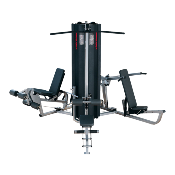
Page 1: Assembly Instructions
FIT SERIES FIT-3 W/ LEG PRESS ASSEMBLY INSTRUCTIONS Part # 7348201 Revision:4/04/03 Rev C. - Page 2 DESCRIPTION PART # COUNTERBALANCE ACU04-1360 FOOT REST ACU04-1367 SEAT PAD SUPPORT ACU04-1361 PRESS ARM ACU04-1338 PIVOT ARM ACU04-1359 MULTI PRESS SEAT ADJUST ACU04-1358 BACK PAD SUPPORT ACU04-1362 MULTI PRESS FRAME ACU04-1356 TOWER UPRIGHT ACU04-1355 TOWER BASE ACU04-1352 LAT/LOW BOOM ACU04-1365 KNEE HOLD DOWN ACU04-1364 LAT/LOW SEAT...
-
Page 3: Tools Required For Assembly
PART # DESCRIPTION ACU10-0205BLK LEG PRESS SHROUD ACU04-1377 LEG PRESS FRAME ACU04-1378 HANDLE ACU04-1379 MAIN PIVOT ARM ACU04-1380 SECONDARY PIVOT ARM ACU04-1381 FOOT PLATE LEG PRESS PLACARD ACU07-0161 LEG PRESS SEAT PAD ACU07-0159 LEG PRESS BACK PAD ACU13-0125 LEG PRESS CABLE ACU06-0025 4-1/2”... - Page 4 49 3/8 X 25mm BOLT 50 3/8 X 32mm BOLT 99 3/8 X 43mm BOLT 52 3/8 X 43mm BOLT W/NYLOCK 3/8 X 50mm BOLT 54 3/8 X 61mm BOLT 3/8 X 67mm BOLT 3/8 X 70mm BOLT 3/8 X 73mm BOLT 3/8 X 117mm BOLT 3/8”...
- Page 5 58 3/8 X 90mm BOLT 59 3/8 X 97mm BOLT 60 3/8 X 106mm BOLT 61 3/8 X 164mm BOLT 62 3/8 X 25mm BUTTON HEAD BOLT 1/2” FLANGE SPACER 63 3/8 X 76mm BUTTON HEAD BOLT 3/4” FLANGE SPACER 22 1/2 X 3”...
- Page 6 3/8 X 97mm 59 FIGURE 1 STEP 1: • LOOSELY assemble the LAT/LOW FRAME (14) to the TOWER BASE (10) using four RH CAPS (69), two 3/8 X 97mm BOLTS (59), four 3/8” SAE WASHERS (66), four 3/8” RH WASHERS (67) and two 3/8” LOW HEIGHT LOCK NUTS (65) as shown in FIGURE 1.
- Page 7 FIGURE 2 STEP 2: • LOOSELY assemble the LEG PRESS FRAME (85) to the TOWER BASE (10) using four RH CAPS (69), two 3/8 X 117mm BOLTS (104), four 3/8” SAE WASHERS (66), four 3/8” RH WASHERS (67) and two 3/8” LOW HEIGHT LOCK NUTS (65) as shown in FIG- URE 2.
- Page 8 FIGURE 3 STEP 3: • LOOSELY assemble the TOWER UPRIGHT (9) to the TOWER BASE (10) using four RH CAPS (69), two 3/8 X 97mm BOLTS (59), four 3/8” SAE WASHERS (66), four 3/8” RH WASHERS (67) and two 3/8” LOW HEIGHT LOCK NUTS (65) as shown in FIGURE 3. (NOTE: REPLACE CAP AFTER ASSEMBLY.) REMOVE CAP BEFORE ASSEMBLY! 59 3/8 X 97mm...
- Page 9 FIGURE 4 STEP 4: • LOOSELY assemble the MULTI PRESS FRAME (8) to the LEG PRESS FRAME (85) using eight RH CAPS (69), two 3/8 X 117mm BOLTS (104), two 3/8 X 67mm BOLTS (55), eight 3/8” SAE WASHERS (66), eight 3/8” RH WASHERS (67) and four 3/8” LOW HEIGHT LOCK NUTS (65) as shown in FIGURE 4.
- Page 10 STEP 5: • Insert two GUIDE RODS (33) through the SHROUD SUPPORT BRACKET (16) and into the TOWER BASE (10) as shown on FIGURE • (NOTE: Lubricate GUIDE RODS (33) with silicon or teflon spray available at most hardware stores.) •...
- Page 11 FIGURE 6 STEP 6: • CAREFULLY slide three SHROUD BRACKETS (15) over all the GUIDE RODS (33) as shown in FIGURE 6. • CAREFULLY assemble the LAT/LOW BOOM (11) over all the GUIDE RODS (33) as shown in FIGURE 6.
- Page 12 FIGURE 7 STEP 7: • LOOSELY assemble the LAT/LOW BOOM (11) to the LAT/LOW FRAME (14) and the TOWER UPRIGHT (9) using seven RH CAPS (69), two 3/8 X 73mm BOLTS (57), two 3/8 X 90mm BOLTS (58), seven 3/8” SAE WASHERS (66), seven 3/8” RH WASHERS (67) and three 3/8”...
- Page 13 LUBRICATION NOTE: When finished assembling the Weight Stack, open the lube Pack provided with this unit and apply a thin film of Lubricant around the first 2 to 3 inches of each Guide Rod above the Head Plate Assembly. After the cables are installed, use of the machine will spread the lubricant over the length of the Guide Rods and into the Head Plate Assemblies bushings...
- Page 14 FIGURE 10 STEP 10: • Insert four 5-1/2” PIVOT SHAFTS (41) into the LAT/LOW FRAME (14) and the LAT/LOW SEAT (13) as shown in FIGURE 10. • SECURELY assemble four LAT/LOW PLATES (19) to the LAT/LOW SEAT (13) and to the LAT/LOW FRAME (14) using eight BLACK RH CAPS (68), four 3/8 X 164mm BOLTS (61), eight 3/8”...
- Page 15 3/8 X 50mm 53 BLACK 68 FIGURE 12 STEP 12: • SECURELY assemble LAT SEAT PAD (42) to the LAT/LOW SEAT (13) using two BLACK RH CAPS (68), two 3/8 X 50mm BOLTS (53), two 3/8” SAE WASHERS (66) and two 3/8” RH WASHERS (67) as shown in FIGURE 12. FIGURE 13 STEP 13: •...
- Page 16 FIGURE 14 STEP 14: • SECURELY assemble the LAT/LOW ADJUST PLATE (21) to the LAT/LOW FRAME (14) using two BLACK RH CAPS (68), two RH CAPS (69), two 3/8 X 67mm BOLTS (55), four 3/8” SAE WASHERS (66), four 3/8” RH WASHERS (67) and two 3/8” LOW HEIGHT LOCK NUTS (65) as shown in FIGURE 14.
- Page 17 FIGURE 16 STEP 16: • Route the LAT CABLE (71) through the LAT/LOW BOOM (11) and assemble two 4-1/2” PULLEYS (26) to the BOOM (11) us- ing two BLACK RH CAPS (68), two RH CAPS (69), two 3/8 X 70mm BOLTS (56), four 3/8” SAE WASHERS (66), four 3/8” RH WASHERS (67), two 2-7/8 X 2-1/4”...
- Page 18 STEP 17: • Route the ROW CABLE (72) around one 4-1/2” PULLEY (26) and assemble the 4-1/2” PULLEY and one 3-1/2” PULLEY (27) to the SWIVEL PULLEY (17) using six BLACK RH CAPS (68), three 3/8 X 43mm BOLTS (51), six 3/8” SAE WASHERS (66), six 3/8” RH WASHERS (67) and three 3/8”...
- Page 19 FIGURE 18 STEP 18: • Route the ROW CABLE (72) around one 4-1/2” PULLEY (26) and assemble the PULLEY to the bottom holes of the DUAL PULLEY PLATES (23) using two RH CAPS (69), one 3/8 X 43mm BOLT (51), two 3/8” SAE WASHERS (66), two 3/8” RH WASHERS (67) and one 3/8”...
- Page 20 STEP 19: • SECURELY assemble the KNEE HOLD DOWN (12) to the LAT/LOW FRAME (14) using two RH CAPS (69), one 3/8 X 164mm BOLT (61), two 3/8” SAE WASHERS (66), two 3/8” RH WASHERS (67) and one 3/8” LOW HEIGHT LOCK NUT (65) as shown in FIGURE 19. •...
- Page 21 FIGURE 20 STEP 20: • Pull back on the SPRING PIN and slide the MULTI PRESS SEAT ADJUST (6) over the MULTI PRESS SLIDE TUBE (24) as shown in FIGURE 20. • Slide the end of the MULTI PRESS SLIDE TUBE (24) over the MULTI PRESS FRAME (8) as shown in FIGURE 20. 3/8 X 25mm 49 FIGURE 21 STEP 21:...
- Page 22 FIGURE 22 STEP 22: • Insert one 5-1/2” PIVOT SHAFT (41) into the MULTI PRESS FRAME (8) and one 5-1/2” PIVOT SHAFT (41) into the BACK PAD SUPPORT (7) as shown in FIGURE 22. 3/8 X 164mm 61 60 3/8 X 106mm STEP 23: •...
- Page 23 3/8 X 73mm 57 BLACK 3/8 X 32mm 50 STEP 25: • Slide two 3” ACCORIDIAN SLEEVES (31) over the shafts on the PIVOT ARM (5) as shown in FIGURE 25. • Slide two PILLOW BLOCKS (25) over the shafts on the PIVOT ARM (5) as shown in FIGURE 25.
- Page 24 FIGURE 26 STEP 26: • SECURELY assemble the PIVOT ARM (5) to the LEG CURL/EXT FRAME (92) using four previously inserted 3/8 X 76mm BUTTON HEAD BOLTS (63), four RH WASHERS (67), four 3/8” SAE WASHERS (66), four 3/8” LOW HEIGHT LOCK NUTS (65) and four RH CAPS (69) as shown in FIGURE 26.
- Page 25 3/8 X 61m 54 3/8 X 43mm 52 W/LOCTITE FIGURE 28 STEP 28: • SECURELY assemble the PRESS ARM (4) to the PIVOT ARM (5) using two RH CAPS (69), two 3/8 X 43mm BOLTS W/LOCTITE (52), two 3/8” SAE WASHERS (66) and two 3/8” RH WASHERS (67) as shown in FIGURE 28. •...
- Page 26 68 BLACK 3/8 X 70mm 56 3/8 X 67mm 55 STEP 29: • Route the MULTI PRESS CABLE (73) through the MULTI PRESS FRAME (8) and assemble one 4-1/2” PULLEY (26) to the FRAME (8) using four RH CAPS (69), one 3/8 X 67mm BOLT (55), one 3/8 X 61mm BOLT (54), four 3/8” SAE WASHERS (66), four 3/8”...
- Page 27 3/8 X 43mm 51 STEP 30: • Route the MULTI PRESS CABLE (73) through the bracket on the MULTI PRESS FRAME (8) and assemble one 4-1/2” PULLEY (26) to the FRAME (8) using four RH CAPS (69), two 3/8 X 43mm BOLTS (51), four 3/8” SAE WASHERS (66), four 3/8” RH WASH- ERS (67) and two 3/8”...
- Page 28 FIGURE 31 STEP 31: • Route the MULTI PRESS CABLE (73) under the weight stack and through the bracket on the TOWER BASE (10) and assemble one 4-1/2” PULLEY (26) to the TOWER BASE (10) using two 3/8 X 43mm BOLTS (51), four 3/8” SAE WASHERS (66) and two 3/8” LOW HEIGHT LOCK NUTS (65) as shown in FIGURE 31.
- Page 29 FIGURE 32 3/8 X 70mm 56 STEP 32: • Route the MULTI PRESS CABLE (73) through the LAT/LOW BOOM (11) and assemble one 4-1/2” PULLEY (26) to the BOOM (11) using one BLACK RH CAP (68), one RH CAP (69), one 3/8 X 70mm BOLT (56), two 3/8” SAE WASHERS (66), two 3/8” RH WASHERS (67), one 2-7/8”...
- Page 30 FIGURE 33 STEP 33: • SECURELY assemble the STORAGE UPRIGHT (75) to the TOWER BASE (10) using four RH CAPS (69), two 3/8 X 90mm BOLTS (58), four 3/8” SAE WASHERS (66), four 3/8” RH WASHERS (67) and two 3/8” LOW HEIGHT LOCK NUTS (65) as shown in FIGURE 33.
- Page 31 STEP 34: • Slide one WEIGHT STACK SELECTOR PIN (38) over the shaft on the HEAD PLATE (36) as shown in FIGURE 34. • Screw the threaded end of the FLOATING PUL- LEY CABLE (111) all the way onto the end of the shaft on the HEAD PLATE (36) and tighten jam nut securely.
- Page 32 FIGURE 35 STEP 35: • Screw the threaded end of the FLOATING PULLEY CABLE (111) all the way onto the end of the shaft on the LAT/LOW ROW BOOM (11) and tighten jam nut securely. See FIGURE 35.
- Page 33 FIGURE 36 STEP 36: • SECURELY assemble the HANDLE (86) to the LEG PRESS FRAME (85) using four RH CAPS (109), two 3/8 X 67mm BOLTS (101), four 3/8” SAE WASHERS (106), four 3/8” RH WASHERS (107) and two 3/8” LOW HEIGHT LOCK NUTS (105) as shown in FIGURE 1”...
- Page 34 FIGURE 38 STEP 38: • SECURELY assemble the FOOT PLATE (89) to the MAIN & SECONDARY PIVOT ARMS (87 & 88) using four RH CAPS (109), two 3/8 X 117mm BOLTS (104), four 3/8” SAE WASHERS (106), four 3/8” RH WASHERS (107), and two 3/8” LOW HEIGHT LOCK NUTS (105) as shown in FIGURE 38.
- Page 35 FIGURE 40 STEP 40: • SECURELY assemble theLEG PRESS SEAT PAD (91) to the LEG PRESS FRAME (85) using two RH CAPS (109), two 3/8 X 73mm BOLTS (103),two 3/8” SAE WASHERS (106) and two 3/8” RH WASHERS (107) as shown in FIGURE 40. FIGURE 41 STEP 41: •...
- Page 36 3/8 X 117mm FIGURE 42 STEP 42: • Assemble the swivel end of the LEG PRESS CABLE (93) to the LEG PRESS FRAME (85) using two RH CAPS (109), one 3/8 X 117mm BOLT (104), two 3/8 X 1-1/2” FLANGE SPACERS (97), two 3/8” SAE WASHERS (106), two 3/8” RH WASHERS (107) and one 3/8” LOW HEIGHT LOCK NUT (105) as shown in FIGURE 42.
- Page 37 FIGURE 44 STEP 44: • Route the LEG PRESS CABLE (93) under the weight stack and through the bracket on the TOWER BASE (10) and assemble one 4-1/2” PULLEY (94) to the TOWER BASE (10) using two 3/8 X 43mm BOLTS (99), four 3/8” SAE WASHERS (106) and two 3/8” LOW HEIGHT LOCK NUTS (105) as shown in FIGURE 44.
- Page 38 STEP 45: • Screw the threaded end of the LEG PRESS CABLE (93) all the way onto the end of the shaft on the PULLEY BRACKET (110) and tighten jam nut securely. See FIGURE 45. • Please refer back to the MAIN UNIT PARTS LIST to complete assembly.
- Page 39 FIGURE 46 STEP 46: • Assemble the LOW ROW BAR (80) to the ROW CABLE (72) using two SNAP LINKS (78) and one 12-LINK CHAIN (77) as shown in FIGURE 46. • Assemble the LAT BAR (79) to the LAT CABLE (71) using one SNAP LINK (78) as shown in FIGURE 46.
- Page 40 FIGURE 47 STEP 47: • Adjustments can be made in the above locations to set the correct amount of tension in the cables. • If upon completion of assembly, the HEAD PLATE (36) does not sit on top of the first WEIGHT PLATE (34), push the HEAD PLATE (36) down, insert the WEIGHT STACK PIN (38) and perform several repetitions.
- Page 41 • Assemble the LEG PRESS PLACARD (90) to the LEG PRESS SHROUD (84) as shown in FIGURE 48. Thank you for purchasing the LifeFitness FIT 3. If unsure of proper use of equipment, call your local LifeFitness distributor or call the LifeFitness customer service department at...
-
Page 42: Warranty Information
There is a risk assumed by individuals who use this type of equipment. To minimize risk, please follow these rules: 1. Inspect equipment daily. Tighten all loose connections and replace worn parts immediately. Failure to do so may result in serious injury. 2.