Table of Contents
Advertisement
Quick Links
Advertisement
Table of Contents

Related Manuals for Supero X9SPV-M4


Summary of Contents for Supero X9SPV-M4
- Page 1 X9SPV-M4 X9SPV-M4-3QE X9SPV-M4-3UE USER’S MANUAL Revision 1.0a...
- Page 2 The information in this User’s Manual has been carefully reviewed and is believed to be accurate. The vendor assumes no responsibility for any inaccuracies that may be contained in this document, makes no commitment to update or to keep current the information in this manual, or to notify any person or organization of the updates.
-
Page 3: About This Manual
X9SPV motherboard product (M series). This product is intended to be professionally installed and serviced by a technician. About This Motherboard The X9SPV-M4 Motherboard is a value-driven product aimed at users who demand a small form-factor, ultra low-power motherboard for storage, server, client, control board and many embedded applications. -
Page 4: Conventions Used In The Manual
X9SPV-M4 Motherboard User’s Manual Conventions Used in the Manual: Special attention should be given to the following symbols for proper installation and to prevent damage done to the components or injury to yourself: Danger/Caution: Instructions to be strictly followed to prevent catastrophic... -
Page 5: Contacting Supermicro
Contacting Supermicro Contacting Supermicro Headquarters Address: Super Micro Computer, Inc. 980 Rock Ave. San Jose, CA 95131 U.S.A. Tel: +1 (408) 503-8000 Fax: +1 (408) 503-8008 Email: marketing@supermicro.com (General Information) support@supermicro.com (Technical Support) Web Site: www.supermicro.com Europe Address: Super Micro Computer B.V. Het Sterrenbeeld 28, 5215 ML 's-Hertogenbosch, The Netherlands Tel:... -
Page 6: Table Of Contents
X9SPV-M4 Quick Reference ................1-4 Jumper Descriptions ..................1-4 Ports, LEDs, and Connectors ................. 1-5 Motherboard Features ..................1-6 X9SPV-M4 Motherboard Block Diagram ............1-8 Chipset Overview ................... 1-9 PC Health Monitoring ..................1-10 Recovery from AC Power Loss ..............1-10 Onboard Voltage Monitoring ................ - Page 7 Table of Contents How to Install SODIMMs ................. 2-4 Memory Support ....................2-4 The SODIMM Socket ..................2-5 Connectors/I/O Ports ..................2-6 Back Panel Connectors and I/O Ports ............2-6 PS/2 KB/Mouse Port (KB/Mouse) .............. 2-7 Universal Serial Bus (USB) ................ 2-8 VESA®...
- Page 8 X9SPV-M4 Motherboard User’s Manual Jumper Settings .................... 2-24 Explanation of Jumpers ................2-24 SMB (I C) Bus to PCI Slots (JI2C1/2) ............2-25 Manufacturing Mode (JPME2)..............2-25 Audio Enable (JPAC1)................2-25 CMOS Clear (JBT1) ................. 2-26 USB Wake-Up (JPUSB1) ................. 2-27 Watch Dog Timer Reset (JWD1) ..............
- Page 9 Table of Contents Quiet Boot ....................4-4 Option ROM Messages ................4-4 Bootup Num-Lock ..................4-4 Wait For 'F1' If Error ................... 4-4 INT19 Trap Response ................4-5 Watch Dog Function ................... 4-5 Power Button Function ................4-5 Restore on AC Power Loss ................ 4-5 ...
- Page 10 X9SPV-M4 Motherboard User’s Manual Serial ATA Port 0~5 Hot Plug ..............4-12 Serial ATA Port 0~5 Spin Up Device ............4-12 RAID Mode ....................4-12 Serial ATA Port 0~5 Hot Plug ..............4-12 Serial ATA Port 0~5 Spin Up Device ............4-12 ...
- Page 11 Table of Contents Intel Anti-Theft Technology Configuration ..........4-21 ® Intel Anti-Theft Technology ..............4-21 ® Intel Anti-Theft Technology Rec .............. 4-21 ® AMT Configuration..................4-21 Intel AMT ....................4-21 Un-Configure ME ..................4-21 WatchDog ....................4-21 iSCSI Configuration ..................4-21 iSCSI Initiator Name ................. 4-22 Add an Attempt ..................
- Page 12 X9SPV-M4 Motherboard User’s Manual Exit ........................ 4-28 Discard Changes and Exit ..............4-28 Save Changes and Reset ................ 4-28 Discard Changes ..................4-28 Restore Defaults ..................4-28 Save As User Defaults ................4-29 Restore User Defaults ................4-29 Boot Override ................... 4-29 Me FW Image Re-Flash ................
-
Page 13: Chapter 1 Introduction
Chapter 1: Introduction Chapter 1 Introduction Overview Checklist Congratulations on purchasing your computer motherboard from an acknowledged leader in the industry. Supermicro boards are designed with the utmost attention to detail and to provide you with the highest standards in quality and performance. Please check that the following items have all been included with your motherboard. -
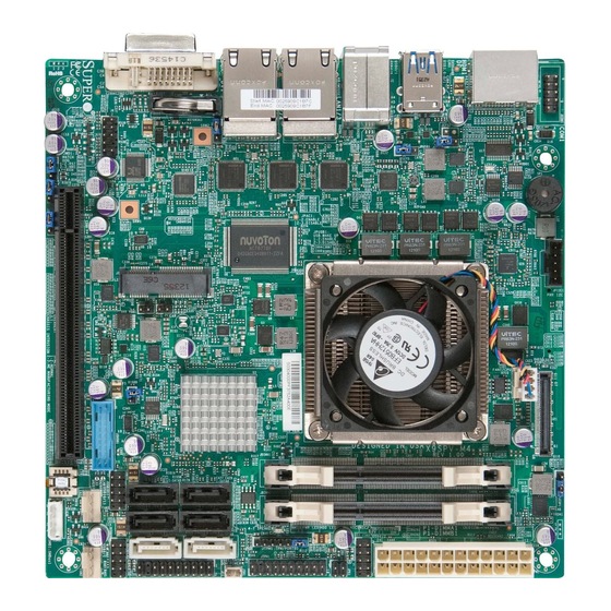
Page 14: X9Spv-M4 Image
X9SPV-M4 Motherboard User's Manual X9SPV-M4 Image Note: All graphics and images shown in this manual were based upon the latest PCB Revision available at the time of publishing of the manual. The motherboard you've received may or may not look exactly the same as the image shown in... -
Page 15: X9Spv-M4 Motherboard Layout
Chapter 1: Introduction X9SPV-M4 Motherboard Layout JLAN2 JLAN1 Battery AUDIO FP SRW2 JRF2 JPUSB1 JWD1: WATCH LED2 1-2:RST 2-3:NMI JPAC1: JRF1 1-2:ENABLE 2-3:DISABLE JPUSB1: USB WAKE UP 1-2:ENABLE 2-3:DISABLE mini PCIE JPI2C1 PWR I2C JOH1 JI2C2 JBT1 FAN1/CPU JPME2 USB3.0-2/3... -
Page 16: X9Spv-M4 Quick Reference
X9SPV-M4 Motherboard User's Manual X9SPV-M4 Quick Reference (not drawn to scale) JLAN2 JLAN1 Battery AUDIO FP JPUSB1 JWD1: WATCH 1-2:RST 2-3:NMI JPAC1: JRF1 1-2:ENABLE 2-3:DISABLE JPUSB1: USB WAKE UP 1-2:ENABLE 2-3:DISABLE mini PCIE JPI2C1 PWR I2C JOH1 JI2C2 JBT1 FAN1/CPU JPME2 USB3.0-2/3... -
Page 17: Ports, Leds, And Connectors
Chapter 1: Introduction Ports, LEDs, and Connectors Item # Connector Description Please see "Back Panel IO Connectors" below, right Back Panel I/O AUDIO FP Front Panel Audio Header SLOT1 PCI-E 3.0 X16 Slot USB 2/3 USB Header for USB Ports 2/3 (USB 3.0) USB 10/11,8/9,6/7 USB Headers for USB Ports 10/11,8/9,6/7 (USB 2.0) 9,13... -
Page 18: Motherboard Features
X9SPV-M4 Motherboard User's Manual Motherboard Features Onboard, Mobile ECC, 3rd generation Intel® Core™ i7 processor (FCBGA1023) X9SPV-M4 Core i7-3555LE, 25W, Dual Core X9SPV-M4-3QE Core i7-3612QE, 35W, Quad Core X9SPV-M4-3UE Core i7-3517UE, 17W, Dual Core Memory Two (2) SO-DIMM slots support up to 16 GB of DDR3/L,... - Page 19 Chapter 1: Introduction Super I/O Nuvoton NCT6776F BIOS 128 Mb SPI AMI BIOS SM Flash BIOS ® Plug and Play, ACPI 4.0, USB Keyboard and SMBIOS 2.7.1 Power ACPI/ACPM Power Management Main Switch Override Mechanism Suspend-To-RAM (STR) One (1) Disk-On-Module (DOM) Power Connector Power-on mode for AC power recovery PC Health Monitoring CPU Monitoring...
-
Page 20: X9Spv-M4 Motherboard Block Diagram
X9SPV-M4 Motherboard User's Manual X9SPV-M4 Motherboard Block Diagram (Or PCIe3.0 2x8) Intel CPU PCIe3.0_x16 FCBGA 1023 PCIe x16 SLOT DDR3 (CHA) 8.0GT/s ECC-SODIMM1 1600/1333 MHz Core i7 SVID DDR3 (CHB) ECC-SODIMM2 1600/1333 MHz IMVP 7 PCIe1.0_x1 GLAN1 SATA 6Gb/s 2x SATA PORTS... -
Page 21: Chipset Overview
Chapter 1: Introduction Chipset Overview The X9SPV-M4 Motherboard supports a single on board, 3rd generation Intel® Core™ i7 processor (FCBGA1023 Mobile ECC CPU). Built around the functionality and the capability of the Intel® QM77 Express chipset, the motherboard provides substantial system performance and storage capability for performance platforms in a compact package. -
Page 22: Pc Health Monitoring
SD III. Fan Status Monitor with Software The PC health monitor can check the RPM status of the cooling fans via Supero Doctor III. 1-10... -
Page 23: 1-4 Power Configuration Settings
It is even more important for processors that have high CPU clock rates of 1 GHz and faster. X9SPV-M4 Motherboard accommodates 12V ATX power supplies. Although most power supplies generally meet the specifications required by the CPU, some are inadequate. A 2-Amp of current supply on a 5V Standby rail is strongly recommended. -
Page 24: Super I/O
X9SPV-M4 Motherboard User's Manual Super I/O The Super I/O provides two high-speed, 16550 compatible serial communication ports (UARTs). Each UART includes a 16-byte send/receive FIFO, a programmable baud rate generator, complete modem control capability and a processor interrupt system. Both UARTs provide legacy speed with baud rate of up to 115.2 Kbps as well as an advanced speed with baud rates of 250 K, 500 K, or 1 Mb/s, which sup- port higher speed modems. -
Page 25: Chapter 2 Installation
Chapter 2: Installation Chapter 2 Installation Static-Sensitive Devices Electrostatic-Discharge (ESD) can damage electronic com ponents. To prevent dam- age to your system board, it is important to handle it very carefully. The following measures are generally sufficient to protect your equipment from ESD. Precautions •... -
Page 26: Tools Needed
Stand Offs (4 pieces) Pan head screws (4 pieces) (Only if needed) Note: The above items are not provided with this motherboard. Location of Mounting Holes There are four (4) mounting holes on the X9SPV-M4 Motherboard. JLAN2 JLAN1 Battery AUDIO FP... -
Page 27: Installation Instructions
Chapter 2: Installation Caution: To avoid damaging the motherboard and its components, please do not use a force greater than 8 lb/inch on each mounting screw during motherboard installation. Installation Instructions Install the I/O shield into the chassis. I/O Shield Locate the mounting holes on the motherboard. -
Page 28: System Memory
Note: Check the Supermicro website for a list of ECC SODIMM that have been validated with the X9SPV-M4 Motherboard. How to Install SODIMMs 1. Insert the desired number of SODIMMs into the memory slots, starting with DIMMA1, then DIMMB1. -
Page 29: The Sodimm Socket
Chapter 2: Installation The SODIMM Socket Position the SODIMM module's bottom key so it aligns with the receptive point on the Align slot. Take note of the module's side notches and the locking clips on the socket. Insert the SODIMM module straight down. -
Page 30: Connectors/I/O Ports
X9SPV-M4 Motherboard User's Manual Connectors/I/O Ports The I/O ports are color coded in conformance with the PC 99 specification. See the figure below for the colors and locations of the various I/O ports. Back Panel Connectors and I/O Ports JLAN2... -
Page 31: Ps/2 Kb/Mouse Port (Kb/Mouse)
Chapter 2: Installation PS/2 KB/Mouse Port (KB/Mouse) PS/2 KB/Mouse Pin Definitions The PS/2 keyboard/mouse port is lo- Pin# Definition cated above the Back Panel USB Ports KB Data on the motherboard. See the table at right for pin definitions. MS Data Ground KB CLK MS CLK... -
Page 32: Universal Serial Bus (Usb)
X9SPV-M4 Motherboard User's Manual Universal Serial Bus (USB) Front Panel USB 2.0 Pin Definitions Four Universal Serial Bus ports (USB 4/5, Pin # Definition Pin # Definition 0/1) are located on the I/O backpanel. Additionally, three USB 2.0 headers USB_N1 USB_N2 (USB 6/7, 8/9, 10/11) and one USB 3.0... -
Page 33: Vesa® Displayport™ (Displayport)
It can connect to virtually any display device using an active Display- Port adapter for devices such as VGA, DVI or HDMI. The X9SPV-M4 supports the DisplayPort standard version 1.1a. HDMI Port One HDMI (High-Definition Multimedia Interface) Port is located next to the LAN2 Connector on the I/O backpanel. -
Page 34: Lan Ports (Lan1~Lan4)
X9SPV-M4 Motherboard User's Manual LAN Ports (LAN1~LAN4) RJ45/LAN Pin Definitions Four (4) gigabit LAN ports are located on Pin # Definition Pin # Definition the I/O back panel. These ports accept TX_D1+ BI_D3- RJ45 type cables. These are used to... -
Page 35: Front Control Panel
Chapter 2: Installation Front Control Panel JF1 contains header pins for various buttons and indicators that are normally lo- cated on a control panel at the front of the chassis. These connectors are designed specifically for use with Supermicro server chassis. See the figure below for the descriptions of the various control panel buttons and LED indicators. -
Page 36: Front Control Panel Pin Definitions
X9SPV-M4 Motherboard User's Manual Front Control Panel Pin Definitions Power LED Power LED Pin Definitions (JF1) The Power LED connection is located on Pin# Definition pins 15 and 16 of JF1. Refer to the table +3.3V on the right for pin definitions. -
Page 37: Overheat (Oh)/Fan Fail/Power Fail/Uid Led
Chapter 2: Installation Overheat (OH)/Fan Fail/Power Fail/ OH/Fan Fail LED UID LED Pin Definitions (JF1) Pin# Definition Connect an LED Cable to the OH/Fan Fail connection on pins 7 and 8 of JF1 Ground to provide advanced warnings of chassis overheat, Unit ID status, power or fan OH/Fan Fail Indicator Status failure. -
Page 38: Power Fail Led
X9SPV-M4 Motherboard User's Manual Power Fail LED Power Fail LED Pin Definitions (JF1) The Power Fail LED connection is lo- Pin# Definition cated on pins 5 and 6 of JF1. Refer to the table on the right for pin definitions. -
Page 39: Connecting Cables
JPUSB1: USB WAKE UP 1-2:ENABLE 2-3:DISABLE mini PCIE JPI2C1 PWR I2C JOH1 JI2C2 JBT1 FAN1/CPU JPME2 USB3.0-2/3 X9SPV-M4 JDIMM1 JWOR1 JWOR1: Wake on Ring I-SATA5 I-SATA4 JDIMM2 UNB ECC DDR3 SODIMM REQUIRED JSMB1 FAN3 I-SATA3 I-SATA2 JD1:1-3 PWR LED P1-DIMMA1... -
Page 40: Fan Headers
X9SPV-M4 Motherboard User's Manual Fan Headers Fan Header Pin Definitions The X9SPV-M4 Motherboard has three Pin# Definition fan headers (Fan1~Fan3). These fans Ground are 4-pin fan headers. Although Pins 1~3 +12V of the fan headers are backward compat- Tachometer ible with the traditional 3-pin fans, please... -
Page 41: Chassis Intrusion (Jl1)
1-2:ENABLE 2-3:DISABLE mini PCIE JPI2C1 PWR I2C JOH1 JI2C2 JBT1 Chassis Intrusion TPM Header FAN1/CPU JPME2 USB3.0-2/3 X9SPV-M4 JDIMM1 JWOR1 JWOR1: Wake on Ring I-SATA5 I-SATA4 JDIMM2 UNB ECC DDR3 SODIMM REQUIRED JSMB1 FAN3 I-SATA3 I-SATA2 JD1:1-3 PWR LED P1-DIMMA1... -
Page 42: Sata Dom Power (Jsd1)
X9SPV-M4 Motherboard User's Manual SATA DOM Power (JSD1) SATA DOM Power Pin Definitions The SATA DOM Power on JSD1 is used Pin# Definition to supply power to SATA Disk-on-Module (DOM) solid-state storage devices. Ground Ground Power SMB I C Connector (JPI2C1) -
Page 43: Overheat/Fan Fail Led (Joh1)
JPUSB1: USB WAKE UP 1-2:ENABLE 2-3:DISABLE mini PCIE JPI2C1 PWR I2C JOH1 JI2C2 JBT1 FAN1/CPU JPME2 USB3.0-2/3 X9SPV-M4 JDIMM1 JWOR1 JWOR1: Wake on Ring I-SATA5 I-SATA4 JDIMM2 UNB ECC DDR3 SODIMM REQUIRED JSMB1 FAN3 I-SATA3 I-SATA2 JD1:1-3 PWR LED P1-DIMMA1... -
Page 44: Power Led/Speaker (Jd1)
X9SPV-M4 Motherboard User's Manual Power LED/Speaker (JD1) On the JD1 header, pins 1~3 are used Speaker Connector Pin Definitions for an external power LED and pins 4~7 Pin Setting Definition are used for an external speaker. If you Pins 6-7... -
Page 45: Lan3 And Lan4 Led Header (Jpk1)
JPUSB1: USB WAKE UP 1-2:ENABLE 2-3:DISABLE mini PCIE JPI2C1 PWR I2C JOH1 JI2C2 JBT1 FAN1/CPU JPME2 USB3.0-2/3 X9SPV-M4 JDIMM1 JWOR1 JWOR1: Wake on Ring I-SATA5 I-SATA4 JDIMM2 UNB ECC DDR3 SODIMM REQUIRED JSMB1 FAN3 I-SATA3 I-SATA2 JD1:1-3 PWR LED P1-DIMMA1... -
Page 46: Embedded Displayport (Edp)
X9SPV-M4 Motherboard User's Manual Embedded DisplayPort (eDP) Embedded DisplayPort (eDP) Pin Definitions The eDP header is used to connect an Pin# Definition Pin# Definition embedded display LED or LCD Panel. LCD_VCC Lane0_N eDP is a companion standard to the LCD_VCC... -
Page 47: Mini Pci-E Slot (Mini Pcie)
JPUSB1: USB WAKE UP 1-2:ENABLE 2-3:DISABLE mini PCIE JPI2C1 PWR I2C JOH1 JI2C2 JBT1 FAN1/CPU JPME2 USB3.0-2/3 X9SPV-M4 JDIMM1 JWOR1 JWOR1: Wake on Ring I-SATA5 I-SATA4 JDIMM2 UNB ECC DDR3 SODIMM REQUIRED JSMB1 FAN3 I-SATA3 I-SATA2 JD1:1-3 PWR LED P1-DIMMA1... -
Page 48: Jumper Settings
X9SPV-M4 Motherboard User's Manual Jumper Settings Explanation of Jumpers To modify the operation of the motherboard, jumpers can be used to choose between optional settings. Jumpers create shorts between two pins to change the function of the connector. Pin 1 is identified with a square solder pad on the printed circuit board. -
Page 49: Smb (I 2 C) Bus To Pci Slots (Ji2C1/2)
JPUSB1: USB WAKE UP 1-2:ENABLE 2-3:DISABLE mini PCIE JPI2C1 PWR I2C JOH1 JI2C2 JBT1 FAN1/CPU JPME2 USB3.0-2/3 X9SPV-M4 JDIMM1 JWOR1 JWOR1: Wake on Ring I-SATA5 I-SATA4 JDIMM2 UNB ECC DDR3 SODIMM REQUIRED JSMB1 FAN3 I-SATA3 I-SATA2 JD1:1-3 PWR LED P1-DIMMA1... -
Page 50: Cmos Clear (Jbt1)
X9SPV-M4 Motherboard User's Manual CMOS Clear (JBT1) JBT1 is used to clear CMOS. Instead of pins, this "jumper" consists of contact pads to pre- vent accidental clearing of CMOS. To clear CMOS, use a metal object such as a small... -
Page 51: Usb Wake-Up (Jpusb1)
JPUSB1: USB WAKE UP 1-2:ENABLE 2-3:DISABLE mini PCIE JPI2C1 PWR I2C JOH1 JI2C2 JBT1 FAN1/CPU JPME2 USB3.0-2/3 X9SPV-M4 JDIMM1 JWOR1 JWOR1: Wake on Ring I-SATA5 I-SATA4 JDIMM2 UNB ECC DDR3 SODIMM REQUIRED JSMB1 FAN3 I-SATA3 I-SATA2 JD1:1-3 PWR LED P1-DIMMA1... -
Page 52: Watch Dog Timer Reset (Jwd1)
X9SPV-M4 Motherboard User's Manual Watch Dog Timer Reset (JWD1) Watch Dog Timer Reset Jumper Settings Watch Dog Timer (JWD1) is a system Jumper Setting Definition monitor that can reboot the system when Pins 1-2 Reset (default) a software application hangs. Close pins... -
Page 53: Onboard Indicators
JPUSB1: USB WAKE UP 1-2:ENABLE 2-3:DISABLE mini PCIE JPI2C1 PWR I2C JOH1 JI2C2 JBT1 FAN1/CPU JPME2 USB3.0-2/3 X9SPV-M4 JDIMM1 JWOR1 JWOR1: Wake on Ring I-SATA5 I-SATA4 JDIMM2 UNB ECC DDR3 SODIMM REQUIRED JSMB1 FAN3 I-SATA3 I-SATA2 JD1:1-3 PWR LED P1-DIMMA1... -
Page 54: Power Led (Led1)
X9SPV-M4 Motherboard User's Manual Power LED (LED1) Power LED (LED1) An Onboard Power LED is located at Status Definition LED1 on the motherboard. When LED1 System Off is on, the AC power cable is connected, System On / Running the power supply hard switch is on, and the system is on/running. -
Page 55: Serial Ata And Hdd Connections
PCIE I-SATA1 (3.0) JPI2C1 PWR I2C JOH1 JI2C2 I-SATA2 JBT1 I-SATA3 FAN1/CPU JPME2 I-SATA4 USB3.0-2/3 I-SATA5 X9SPV-M4 JDIMM1 JWOR1 JWOR1: Wake on Ring I-SATA5 I-SATA4 JDIMM2 UNB ECC DDR3 SODIMM REQUIRED JSMB1 FAN3 I-SATA3 I-SATA2 JD1:1-3 PWR LED P1-DIMMA1... -
Page 56: Chapter 3 Troubleshooting
Chapter 3: Troubleshooting Chapter 3 Troubleshooting Troubleshooting Procedures Use the following procedures to troubleshoot your system. If you have followed all of the procedures below and still need assistance, refer to the ‘Technical Support Procedures’ and/or ‘Returning Merchandise for Service’ section(s) in this chapter. Always disconnect the AC power cord before adding, changing or installing any hardware components. -
Page 57: Memory Errors
X9SPV-M4 Motherboard User's Manual 2. Use the speaker to determine if any beep codes exist. (Refer to Appendix A for details on beep codes.) 3. Remove all memory modules and turn on the system. (If the alarm is on, check the specs of memory modules, reset the memory or try a different one.) -
Page 58: Frequently Asked Questions
Frequently Asked Questions Question: What type of memory does my motherboard support? Answer: The X9SPV-M4 Motherboard supports up to 16GB of ECC DDR3 1600/1333 MHz, two-way interleaved or non-interleaved SODIMM memory. See Section 2-4 for details on installing memory. Question: Why does Microsoft Windows show less memory than what is... - Page 59 X9SPV-M4 Motherboard User's Manual BIOS warning message and the information on how to update your BIOS on our web site. Select your motherboard model and download the BIOS (.rom) file to your computer. Also, check the current BIOS revision and make sure that it is newer than your BIOS before downloading.
-
Page 60: Returning Merchandise For Service
Chapter 3: Troubleshooting Returning Merchandise for Service A receipt or copy of your invoice marked with the date of purchase is required before any warranty service will be rendered. You can obtain service by calling your vendor for a Returned Merchandise Authorization (RMA) number. When returning to the manufacturer, the RMA number should be prominently displayed on the outside of the shipping carton, and mailed prepaid or hand-carried. - Page 61 X9SPV-M4 Motherboard User's Manual Notes...
-
Page 62: Chapter 4 Bios
BIOS Introduction This chapter describes the AMI BIOS Setup Utility for the X9SPV-M4 Motherboard. The AMI ROM BIOS is stored in a Flash EEPROM and can be easily updated. This chapter describes the basic navigation of the AMI BIOS Setup Utility setup screens. -
Page 63: How To Start The Setup Utility
X9SPV-M4 Motherboard User's Manual How to Start the Setup Utility Normally, the only visible Power-On Self-Test (POST) routine is the memory test. As the memory is being tested, press the <Delete> key to enter the main menu of the AMI BIOS Setup Utility. From the main menu, you can access the other setup screens. -
Page 64: System Overview: The Following Bios Information Will Be Displayed
Day MM/DD/YY format. The time is entered in HH:MM:SS format. (Note: The time is in the 24-hour format. For example, 5:30 P.M. appears as 17:30:00.) Supermicro X9SPV-M4 Version: This item displays the version of the BIOS used in the system. -
Page 65: Advanced Setup Configurations
X9SPV-M4 Motherboard User's Manual Advanced Setup Configurations Use the arrow keys to select Boot Setup and hit <Enter> to access the submenu items: Aptio Setup Utility - Copyright (C) 2012 American Megatrends, Inc. Main Advanced Event Logs Boot Security Exit System Boot Feature Setting. -
Page 66: Int19 Trap Response
Chapter 4: AMI BIOS INT19 Trap Response The Interrupt 19 (INT19) feature determines how the BIOS will react to INT19 trap- ping by Option ROM. If set to Immediate, BIOS will execute the trap right away. If set to Postponed, BIOS will execute the trap during legacy boot. The options are Immediate and Postponed Watch Dog Function If enabled, the Watch Dog timer will allow the system to automatically reboot when... -
Page 67: Limit Cpuid Maximum
X9SPV-M4 Motherboard User's Manual Limit CPUID Maximum This feature allows the user to set the maximum CPU ID value. Enable this function to boot the legacy operating systems that cannot support processors with extended CPUID functions. The options are Enabled and Disabled (for the Windows OS.). -
Page 68: Eist
Chapter 4: AMI BIOS EIST EIST (Enhanced Intel SpeedStep Technology) allows the system to automati- cally adjust processor voltage and core frequency in an effort to reduce power consumption and heat dissipation. Please refer to Intel’s web site for detailed information. The options are Disabled and Enabled. Turbo Mode This feature allows processor cores to run faster than marked frequency in specific conditions. -
Page 69: Advanced Chipset Control
X9SPV-M4 Motherboard User's Manual Advanced Chipset Control WARNING: Setting the wrong values in the following sections may cause the system to malfunction. System Agent (SA) Configuration This submenu allows you to configure System Agent Parameters. Memory Configuration ... -
Page 70: Usb Configuration
Chapter 4: AMI BIOS PEG0 ASPM Set this item to control ASPM (Active State Power Management) support for PEG: Device 1 Function 0. The options are Disabled, Auto, ASPM L0s, ASPM L1, and ASPM L0sL1. Enable PEG Use this feature to enable the PEG. The options are Disabled, Enabled, and Auto. -
Page 71: Pch Azalia Configuration
X9SPV-M4 Motherboard User's Manual EHCI Hand-Off This item is for Operating Systems that do not support Enhanced Host Control- ler Interface (EHCI) hand-off. When enabled, EHCI ownership change will be claimed by the EHCI driver. The settings are Enabled and Disabled. -
Page 72: Ide/Sata Configuration
Chapter 4: AMI BIOS Internal HDMI/Display Port Codec (Available if Azalia set to Enabled) Select Enabled to enable the internal HDMI/Display port codec for Azalia. Wake on LAN Use this feature to activate the Wake On LAN (WOL) feature. The options are Enabled, and Disabled. -
Page 73: Ahci Mode
X9SPV-M4 Motherboard User's Manual AHCI Mode The following items are displayed when AHCI Mode is selected: Aggressive LPM Support Use this feature to enable Aggressive Link Power Management support, which enables PCH to save power by setting the SATA link (to the disk) to a low power state. -
Page 74: Perr# Generation
Chapter 4: AMI BIOS Clocks, 64 PCI Bus Clocks, 96 PCI Bus Clocks, 128 PCI Bus Clocks, 160 PCI Bus Clocks, 192 PCI Bus Clocks, 224 PCI Bus Clocks and 248 PCI Bus Clocks. PERR# Generation Set this item to Enabled to allow PCI devices to generate PERR# error codes. The options are Enabled and Disabled. - Page 75 X9SPV-M4 Motherboard User's Manual No Snoop Select Enabled to activate the PCI Express no snoop option. The options are Disabled and Enabled. Extended Synch Select Enabled for Extended Synchronization support, which will extend the same synchronization patterns for the PCI-E device. The options are Disabled and Enabled.
- Page 76 Chapter 4: AMI BIOS AtomicOp Egress Blocking (Available when supported by the hardware) When set to Enabled, this feature blocks outbound AtomicOp Requests via Egress ports. The options are Disabled and Enabled. IDO Request Enable (Available when supported by the hardware) When set to Enabled, this feature permits setting the number of ID-Based Or- dering (IDO) bit (Attribute[2]) requests to be initiated.
-
Page 77: Pci-E Slot 1 Option Rom
X9SPV-M4 Motherboard User's Manual Hardware Autonomous Width (Available when supported by the hardware) When set to Disabled, this feature disables the hardware's ability to change link width (except width size reduction) for the purpose of correcting unstable link operation. The options are Enabled and Disabled. -
Page 78: Super Io Configuration
Chapter 4: AMI BIOS Super IO Configuration Serial Port 1 Select Enabled to enable the onboard serial port. The options are Enabled and Disabled. Serial Port 1 Settings This option specifies the base I/O port address and the Interrupt Request address of Serial Port 1 and Serial Port 2. - Page 79 X9SPV-M4 Motherboard User's Manual Bits Per Second This item sets the transmission speed for a serial port used in Console Redirec- tion. Make sure that the same speed is used in the host computer and the client computer. A lower transmission speed may be required for long and busy lines.
-
Page 80: Serial Port For Out-Of-Band Management/Windows Emergency Management Services (Ems)
Chapter 4: AMI BIOS Legacy OS Redirection Resolution Use this feature to select the number of rows and columns used in Console Redirection for legacy OS support. The options are 80x24 and 80x25. Putty Keypad Use this feature to select function key and keypad setting on Putty. The options are VT100, LINUX, XTERMR6, SCO, ESCN, and VT400. -
Page 81: Trusted Computing
X9SPV-M4 Motherboard User's Manual Flow Control This feature allows the user to set the flow control for Console Redirection to prevent data loss caused by buffer overflow. Send a "Stop" signal to stop send- ing data when the receiving buffer is full. Send a "Start" signal to start sending data when the receiving buffer is empty. -
Page 82: Intel Txt(Lt) Configuration
Chapter 4: AMI BIOS Intel TXT(LT) Configuration Secure Mode Extensions (SMX) This feature can be configured if it is supported by the processor. Enable this feature to activate Intel TXT, below. The options are Enabled and Disabled. Intel TXT (LT) Support Intel TXT (Trusted Execution Technology) helps protect against software-based at- tacks and ensures protection, confidentiality and integrity of data stored or created on the system. -
Page 83: Iscsi Initiator Name
X9SPV-M4 Motherboard User's Manual application must be configured on the machine that will access the iSCSI drives in this machine. iSCSI Initiator Name Only IQN (iSCSI Qualified Names) names are accepted. For more information on iSCSI, research RFC 3720 and RFC 3721 at the Internet Engineering Task Force website (IETF -- www.ietf.org). -
Page 84: Intel(R) 82579Lm (X1)
Chapter 4: AMI BIOS Delete Attempts This feature deletes previously defined attempts as above. Change Attempt Order This feature changes the order in which several iSCSI connection attempts are made. Intel(R) 82579LM (x1) Intel(R) 82574L Gigabit Network Connection (x3) ... -
Page 85: Event Logs
X9SPV-M4 Motherboard User's Manual Event Logs Aptio Setup Utility - Copyright (C) 2012 American Megatrends, Inc. Main Advanced Event Logs Boot Security Save & Exit Press <Enter> to change the Change Smbios Event Log Settings Smbios Event Log Con guration. -
Page 86: Metw
Chapter 4: AMI BIOS METW The Multiple Event Time Window (METW) defines number of minutes must pass between duplicate log events before MECI is incremented. This is in minutes, from 0 to 99. The default is 60. View SmBIOS Event Log This feature displays the contents of the SmBIOS Event Log. -
Page 87: Boot
X9SPV-M4 Motherboard User's Manual Boot Use this feature to configure Boot Settings: Aptio Setup Utility - Copyright (C) 2012 American Megatrends, Inc. Main Advanced Event Logs Boot Security Save & Exit Setup Prompt Timeout Sets the system boot order Boot Option Priorities Boot Option #1 [PO: WDC WD800AAJS-0...]... -
Page 88: Delete Boot Option
Chapter 4: AMI BIOS Delete Boot Option This feature allows the user to delete a previously defined boot device from which the system boots during startup. Security Settings Aptio Setup Utility - Copyright (C) 2012 American Megatrends, Inc. Main Advanced Event Logs Boot... -
Page 89: Exit
X9SPV-M4 Motherboard User's Manual Exit Select the Exit tab from the BIOS Setup Utility screen to enter the Exit BIOS Setup screen. Aptio Setup Utility - Copyright (C) 2012 American Megatrends, Inc. Main Advanced Event Logs Boot Security Exit Exit system setup without Discard Changes and Exit saving any changes. -
Page 90: Save As User Defaults
Chapter 4: AMI BIOS Save As User Defaults To set this feature, select Save as User Defaults from the Exit menu and press <Enter>. This enables the user to save any changes to the BIOS setup for future use Restore User Defaults To set this feature, select Restore User Defaults from the Exit menu and press <En- ter>. -
Page 91: Appendix A Post Error Beep Codes
Appendix A: POST Error Beep Codes Appendix A POST Error Beep Codes This section lists POST (Power On Self Test) error beep codes for the AMI BIOS. POST error beep codes are divided into two categories: recoverable and terminal. This section lists Beep Codes for recoverable POST errors. Recoverable POST Error Beep Codes When a recoverable type of error occurs during POST, BIOS will display a POST code that describes the problem. - Page 92 X9SPV-M4 Motherboard User's Manual Notes...
-
Page 93: Appendix B Software Installation Instructions
X9SPV-M4 Motherboard User's Manual Appendix B Software Installation Instructions B-1 Installing Software Programs The Supermicro ftp site contains drivers and utilities for your system at ftp://ftp. supermicro.com. Some of these must be installed, such as the chipset driver. After accessing the ftp site, go into the CDR_Images directory and locate the ISO file for your motherboard. -
Page 94: Configuring Superdoctor ® Iii
X9SPV-M4 Motherboard User's Manual Note 2. When making a storage driver diskette by booting into a Driver CD, please set the SATA Configuration to "Compatible Mode" and configure SATA as IDE in the BIOS Setup. After making the driver diskette, be sure to change the SATA settings back to your original settings. - Page 95 X9SPV-M4 Motherboard User's Manual SuperDoctor III Interface Display Screen (Remote Control) Note: SD III Software Revision 1.0 can be downloaded from our Web Site at: ftp://ftp.supermicro.com/utility/Supero_Doctor_III/. You can also download the SDIII User's Guide at: <http://www.supermicro.com/PROD- UCT/Manuals/SDIII/UserGuide.pdf>. For Linux, we will recommend using...
- Page 96 X9SPV-M4 Motherboard User's Manual Notes...
-
Page 97: Appendix C Uefi Bios Recovery Instructions
Appendix C: UEFI BIOS Recovery Appendix C UEFI BIOS Recovery Instructions Warning! Do not upgrade the BIOS unless your system has a BIOS-related issue. Flashing the wrong BIOS can cause irreparable damage to the system. In no event shall Supermicro be liable for direct, indirect, special, incidental, or consequential damages arising from a BIOS update. - Page 98 X9SPV-M4 Motherboard User’s Manual a USB CD/DVD ROM/RW device can be used for this purpose. However, a USB Hard Disk drive cannot be used for BIOS recovery at this time. To perform UEFI BIOS recovery using a USB-attached device, follow the instruc- tions below.
- Page 99 Appendix C: UEFI BIOS Recovery Note: Do not interrupt the process of BIOS flashing until it is completed. 6. After the process of BIOS Recovery is complete, press any key to reboot the system. 7. Using a different system, extract the BIOS package into a bootable USB flash drive.
- Page 100 X9SPV-M4 Motherboard User’s Manual 9. After seeing the message that BIOS update is completed, unplug the AC pow- er cable from the power supply to clear CMOS, and then plug the AC power cable in the power supply again to power on the system.
- Page 101 (Disclaimer Continued) The products sold by Supermicro are not intended for and will not be used in life support systems, medical equipment, nuclear facilities or systems, aircraft, aircraft devices, aircraft/emergency com- munication devices or other critical systems whose failure to perform be reasonably expected to result in significant injury or loss of life or catastrophic property damage.