Table of Contents
Advertisement
CAUTION:
Read entire instruction sheet carefully before beginning installation.
To avoid the possibility of electrical shock, be sure the power is TURNED OFF as its source (fuse
or circuit breaker). All electrical components must be installed in accordance with national and
local electrical codes. To reduce the risk of fire and electrical shock, this remote control should
be used only with CONCORD ceiling fans.
Locate the Hand-held Remote Control Transmitter, the Receiver Unit, and the Wall Control. These three items have a
block of dip switches inside them. See illustrations "i" and "ii" to locate the block of dip switches. Make sure the
switches in all three units are aligned exactly the same way. This system will not function properly unless all switches
are set the same. Insert 1-12 volt battery into the Wall Control Unit (see illustration ii). Insert 1-9 volt battery into the
compartment of the Hand-held Remote Control Transmitter (see illustrations "iii", "iv" & "v").
Figure i
Battery Compartment
Figure iii (Open)
®
BEFORE BEGINNING INSTALLATION STEPS:
Hand-Held Transmitter
Battery
Compartment
Figure v (Close)
Wall
Control
12 volt Battery
Figure ii
Hand-Held Transmitter
Figure iv (Insert Battery)
Lock Clip
Hand-Held
Transmitter
- 1 -
RM-08
(Revised 05.02.2007)
Cover
Battery
Terminal
9 volt
Battery
™
Advertisement
Table of Contents

Summary of Contents for CONCORD RM-08
- Page 1 All electrical components must be installed in accordance with national and local electrical codes. To reduce the risk of fire and electrical shock, this remote control should be used only with CONCORD ceiling fans. BEFORE BEGINNING INSTALLATION STEPS: Locate the Hand-held Remote Control Transmitter, the Receiver Unit, and the Wall Control.
- Page 2 Option to remove wiring from switch housing Screw (3) - Unscrew the metal sleeve where the pull chain comes out of the switch Mounting Plate housing (see figure A). Molex -Remove the speed switch from the hole. -Next, remove the 2 small screws holding the forward/reverse switch in Reverse place (see figure A).
- Page 3 Fan With Uplight only STEP 2 WHITE Lite Make the following connections and place RM-08 wire bundle into the empty switch Kit Wire housing. Remove paper backing from stickers to secure reverse module and capaci- Capacitor tor to the bottom of the shell (see figure 2).
- Page 4 NOTE: If your fan has uplight or motor center band lighting you MUST connect the WHITE Capacitor wire (marked “For Light”) to the BLUE wire coming down from fan (see figure 3B). Mounting Plate STEP 3 Molex Screw (3) Connect the Molex plug from the switch housing unit to the end from the fan. Molex These plugs are notched and will connect in one direction only.
- Page 5 STEP 6: Hanging the fan body Mounting Bracket Notice the half ball on the end of the support rod is grooved down one side. This Keyway fits over the small keyway pin on the inside of the mounting bracket and keeps the ceiling fan from spinning on the mounting bracket. Receiving Unit Lift the fan and place the half ball in the center of the mounting bracket with...
- Page 6 Re-connect the 2 switch wires together and tuck back in switch box to allow room for RM-08. Replace wire nuts. Push the Control Unit into the switch box and secure it with the two screws at each end of the unit (this procedure is the same as if you were to put the original wall switch back into the wall).
-
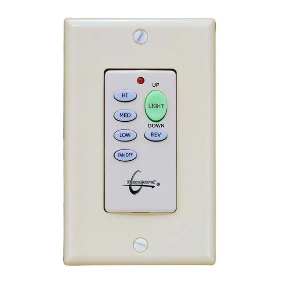
Page 7: Operation Instructions
Operation Instructions 1. WALL CONTROL (see drawing below for the following instructions) Speed Control Press HI, MED, or LOW button to start the fan. Press REV button to reverse air flow direction. Press Fan OFF to stop the fan. Light Control Press DOWN button to turn on the bottom fan lights. - Page 8 No part of this publication may be produced, transmitted, transcribed, stored in a retrieval system, or translated into any language ® in any form by any means without the written permission of Great 2000 Enterprises, Inc.. Concord Fans and Lighting is a division of Great 2000 Enterprises, Inc.