Table of Contents
Advertisement
Quick Links
Installation and Operation Instructions
Installation and Operation
Instructions for
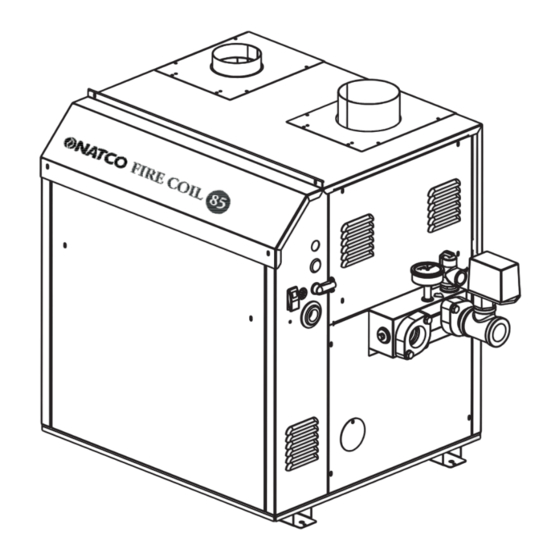
Fire Coil 85
Hydronic Boiler
Model F85H
Water Heater
Model F85V
Sizes 200, 300, 400
This product must be installed and serviced by a professional service technician,
FOR YOUR SAFETY:
qualified in hot water boiler installation and maintenance. Improper installation and/or operation could
create carbon monoxide gas in flue gases which could cause serious injury, property damage, or
death. Improper installation and/or operation will void the warranty. For indoor installations, as an
additional measure of safety, NATCO strongly recommends installation of suitable Carbon Monoxide
detectors in the vicinity of this appliance and in any adjacent occupied spaces.
WARNING
If the information in this manual is not
followed exactly, a fire or explosion may
result causing property damage, personal
injury or loss of life.
Do not store or use gasoline or other
flammable vapors and liquids in the vicinity of
this or any other appliance.
WHAT TO DO IF YOU SMELL GAS
• Do not try to light any appliance.
• Do not touch any electrical switch; do not
use any phone in your building.
• Immediately call your gas supplier from
a nearby phone. Follow the gas supplier's
instructions.
• If you cannot reach your gas supplier, call
the fire department.
Installation and service must be performed
by a qualified installer, service agency, or gas
supplier.
AVERTISSEMENT
Assurez-vous de bien suivres les instructions
données dans cette notice pour réduire au
minimum le risque d'incendie ou d'explosion ou
pour éviter tout dommage matériel, toute blessure
ou la mort.
Ne pas entreposer ni utiliser d'essence ni d'autres
vapeurs ou liquides inflammables dans le voisinage
de cet appareil ou de tout autre appareil.
QUE FAIRE SI VOUS SENTEZ UNE ODEUR DE GAZ:
• Ne pas tenter d'allumer d'appareils.
• Ne touchez à aucun interrupteur. Ne pas vous
servir des téléphones dansle bâtiment où vous
trouvez.
• Appelez immédiatement votre fournisseur de
gaz depuis un voisin. Suivez les instructions
du fournisseur.
• Si vous ne pouvez rejoindre le fournisseur de
gaz, appelez le sservice des incendies.
L'installation et l'entretien doivent être assurés par
un installateur ou un service d'entretien qualifié ou
par le fournisseur de gaz.
Document 1240
Advertisement
Table of Contents

Related Manuals for Natco F85H Fire Coil 85 200

Summary of Contents for Natco F85H Fire Coil 85 200
- Page 1 Improper installation and/or operation will void the warranty. For indoor installations, as an additional measure of safety, NATCO strongly recommends installation of suitable Carbon Monoxide detectors in the vicinity of this appliance and in any adjacent occupied spaces.
-
Page 2: Table Of Contents
National Combustion Co., Inc. Page 2 TABLE OF CONTENTS SECTION 1. General Information SECTION 5. Electrical Connections Introduction ............3 Main Power ............ 24 Model Identifi cation .......... 4 Field Wiring ........... 25 Warranty ............4 SECTION 6. Operating Instructions Dimensions ............ -
Page 3: Section 1. General Information
à défaut de quoi la garantie fournie par NATCO products. Where differences exist between the Heating Systems serait annulée. L’installation doit application of the appliances and their operation, être conforme aux exigences de la réglementation... -
Page 4: Model Identifi Cation
The owner should fi ll out the applicable local codes as required by the AHJ. warranty registration card and return it to NATCO. All electrical wiring is to be done in accordance with: All warranty claims must be made to an 1). - Page 5 Fire Coil 85 (200, 300, 400) Page 5 Dimensions shown in inches, cm. Combustion Air Horizontal Vent Connection Model Connection (Cat III) Vent Pipe Size 20.5 26.5 33.6 *Air and vent connections may be on top or back of the Fire Coil 85, and are fi eld convertible. Figure 1A.
- Page 6 National Combustion Co., Inc. Page 6 Dimensions shown in inches, cm. Combustion Air Horizontal Vent Connection Model Connection (Cat III) Vent Pipe Size 20.5 26.5 33.6 *Air and vent connections may be on top or back of the Fire Coil 85, and are fi eld convertible. Figure 1b.
-
Page 7: Locating Pump-Mounted Water Heater With Respect To Storage Tank(S)
Fire Coil 85 (200, 300, 400) Page 7 Intake Side Wall Heater Vent Collar Horizontal Air Collar Max. Pipe Max. No. Side Vent Combustion Size Size Vent Pipe & Pipe Length of Elbows Terminal Air Terminal Diameter Diameter Part Number Part Number CA003101 CA003201... -
Page 8: Section 2. Venting And Combustion Air
For indoor installations, as an additional measure of or spaces that directly communicate with the outdoors safety, NATCO strongly recommends installation of and shall have a minimum free area of 1 square inch suitable Carbon Monoxide detectors in the vicinity of per 3000 Btu/hr (7 square cm/kW) of the total input this appliance and in any adjacent occupied spaces. -
Page 9: Intake Combustion Air
(without the use of a power venter) are it must be taken from out-of-doors by means of the considered Category III vent systems. NATCO horizontal wall terminal (see Table 1). When taken from the roof, a fi eld-supplied rain cap or an 2.2.2 Category I Vent elbow arrangement must be used to prevent entry of rain water (see Figure 2). -
Page 10: Category Iii Vent
Whenever system should be connected to a NATCO product, possible, locations under windows or near doors please call the NATCO applications department at should be avoided. - Page 11 Fire Coil 85 (200, 300, 400) Page 11 U.S. Installations (see note 1) Canadian Installations (see note 2) A= Clearance above grade, veranda, porch, 12 inches (30 cm) 12 inches (30 cm) deck, or balcony B= Clearance to window or door that may Direct Vent Only: 12 inches (30 cm) be opened Other Than Direct Vent: 4 feet (1.2 m) below or...
- Page 12 National Combustion Co., Inc. Page 12 If the boiler or water heater uses ducted In the event that the requirements of this combustion air from an intake terminal located subdivision cannot be met at the time of on the same wall, locate the vent terminal at least completion of installation, the owner shall 3 feet (0.9m) horizontally from the combustion have a period of thirty (30) days to comply...
-
Page 13: Side Wall Combustion Air Terminal
Visually inspect the venting system for proper 2.3.2 Side Wall Combustion Air Terminal size and horizontal pitch and determine there is The NATCO side wall combustion air terminal non blockage or restriction, leakage, corrosion (listed in Table 1) must be used when the unit takes and other defi... -
Page 14: Vent Terminals For Outdoor Units
Sceller toutes les ouvertures non utilisées du If local codes allow, NATCO kits are not système d'évacuation. required for outdoor units. The installer may use Inspecter de façon visuelle le système 12"... -
Page 15: Section 3. Gas Supply And Piping
Fire Coil 85 (200, 300, 400) Page 15 The appliance and its individual shutoff valve SECTION 3. must be disconnected from the gas supply piping Gas Supply and Piping during any pressure testing of that system at test pressures in excess of 0.5 psig (3.45 kpa). 3.1 Gas Supply and Piping The unit must be isolated from the gas supply Gas piping should be supported by suitable... -
Page 16: Section 4A. Water Connections
National Combustion Co., Inc. Page 16 SECTION 4A. 4A.3 Water Flow Requirements — Boiler A hydronic heating (closed loop) application Water Connections — recirculates the same fl uid in the piping system. As a Fire Coil 85 Boiler result, no new minerals or oxygen are introduced into the system. - Page 17 Fire Coil 85 (200, 300, 400) Page 17 Model 20°F 25°F 30°F 35°F (Size) flow flow flow flow feet feet feet feet Metric Equivalent Model 11°C 14°C 17°C 19°C (Size) fl ow fl ow fl ow fl ow Notes: gpm = gallons per minute, lpm = liters per minute, H/L = head loss, ft = head loss in feet, m = head loss in meters.
- Page 18 National Combustion Co., Inc. Page 18 Figure 5. Hydronic Piping — Multiple Boilers, Low Temperature System. Figure 6. Hydronic Piping — One Boiler, Multi-Temperature System.
- Page 19 Fire Coil 85 (200, 300, 400) Page 19 Figure 7. Hydronic Piping — Primary-Secondary, Reverse-Return. Figure 8. Hydronic Piping — Primary-Secondary, Reverse-Return, Low Temperature.
-
Page 20: Section 4B. Water Connections
Contact Pipe the outlet from the heater’s relief valve a NATCO representative if you have questions or such that any discharge from the relief valve will be concerns about water quality. -
Page 21: Freeze Protection - Water Heater
fl ooding conditions. are not recommended in areas subject to freezing Contact the NATCO applications department at temperatures, unless proper precautions are taken. 718-291-8400 for additional information. Power outage, interruption of gas supply, failure Model Temp Rise °F... - Page 22 National Combustion Co., Inc. Page 22 Figure 9. Water Heater Piping — One Heater, One Tank. Figure 10. Water Heater Piping — Multiple Heaters, One Tank.
- Page 23 Fire Coil 85 (200, 300, 400) Page 23 Figure 11. Water Heater Piping — One Heater, Multiple Tanks. Figure 12. Water Heater Piping — Multiple Heaters, Multiple Tanks.
-
Page 24: Section 5. Electrical Connections
National Combustion Co., Inc. Page 24 SECTION 5. Electrical Connections WARNING Single pole switches, including those of safety The appliance must be electrically grounded in controls and protective devices must not be wired in a accordance with the requirements of the authority grounded line. -
Page 25: Field Wiring
Fire Coil 85 (200, 300, 400) Page 25 5.2 Field Wiring To connect the pump, crimp the two spade connectors to the black (hot) and white (neutral) pump Field Installed Pump: A pump contactor can be wires (as shown in pump diagram, Figure 14). The wired to the “2”... - Page 26 National Combustion Co., Inc. Page 26 Figure 15. Wiring Diagram, ON/OFF Boiler or Water Heater.
- Page 27 Fire Coil 85 (200, 300, 400) Page 27 Figure 16. Wiring Diagram, 2-STAGE Boiler or Water Heater...
- Page 28 National Combustion Co., Inc. Page 28 Figure 17. Logic Diagram, ON/OFF Boiler or Water Figure 18. Logic Diagram, 2-STAGE Boiler or Water Heater. Heater.
-
Page 29: Section 6. Operating Instructions
Fire Coil 85 (200, 300, 400) Page 29 SECTION 6. heat-up time, the main gas terminals will be energized, attempting to light, for seven (7) Operating Instructions seconds, and then will de-energize. The unit will attempt to light two more times, and then will go 6.1 Filling the Boiler System into lockout mode. -
Page 30: Sequence Of Operation
National Combustion Co., Inc. Page 30 When the ignition control gets the signal at the PSW terminal, it will energize its MV terminal, which sends power to the stage one (or on/off) main valve. After a 7-second trial for ignition, the ignitor switches to fl... -
Page 31: Operating The Burner And Set Up
Fire Coil 85 (200, 300, 400) Page 31 6.6 Operating the Burner and Set-Up reset by cycling the power before the unit will operate. 6.6.1 Set-Up for 0 to 2500 Feet Altitude Open gas shutoff valve. Restart the The setup must be checked before the unit is put appliance. -
Page 32: To Restart The Fire Coil 85
7.2 Appliance Maintenance and Component Description Only genuine NATCO replacement parts should be used. Caution Label all wires prior to disconnection when servicing controls. Wiring errors can cause improper and dangerous operation. -
Page 33: Burners
Fire Coil 85 (200, 300, 400) Page 33 a qualifi ed service technician inspect the basic items 7.2.4 Manual Reset High Limit Control listed below every year. The high limit switch is a manual reset, non- Ignition control adjustable switch with a remote bulb-type sensor. Ignitor Switches for water heaters and low temperature boiler Water temperature control... -
Page 34: Flow Switch
National Combustion Co., Inc. Page 34 wires, remove the mounting screws and remove the valve on the heater. transformer. Replace transformer in the reverse order. Disconnect and remove the wires, conduit and sensors from all components that are attached to 7.2.8 Flow Switch the inlet/outlet header. -
Page 35: Resolving Lockouts
There are many causes of lockouts. The three necessary to install a buffer tank in the system. Contact most common causes are: (1) inadequate gas supply, your NATCO representative to discuss possible (2) poor combustion, (3) ignitor failure. remedies. Inadequate gas supply: Before proceeding, ensure that the gas supply has not been shutoff or the LP 8.4 Short Cycling —... -
Page 36: Section 9. Replacement Parts
9.1 General Information To order or purchase parts for the NATCO Fire Coil 85, contact your nearest NATCO dealer or distributor. If they cannot supply you with what you need, contact Customer Service (see back cover for address, telephone and fax numbers). - Page 37 Fire Coil 85 (200, 300, 400) Page 37 Item Description Model 200 Model 300 Model 400 JACKET COMPONENTS See Figure 21 Panel, Front, Jacket R2C3320 R3C3320 R4C3320 Panel, Rear, Jacket 2C3220 3C3220 4C3220 Panel, Top, Jacket 2C3021 3C3021 4C3021 Panel, Jacket, Control Access 2F3019 3F3019 4F3019...
- Page 38 National Combustion Co., Inc. Page 38 Item Description Model 200 Model 300 Model 400 Spacer, Gas Orifi ce F2022400 F2022400 F2022400 Gas Valve, Combination, Nat. (DSI) 3/4" NPT x V0079400 V0079400 V0079400 3/4" NPT Gas Valve, Combination, LP (DSI) 3/4" NPT x V0079500 V0079500 V0079500...
- Page 39 Fire Coil 85 (200, 300, 400) Page 39 Figure 20. Combustion Chamber Components.
- Page 40 National Combustion Co., Inc. Page 40 Figure 21. Jacket Components.
- Page 41 Fire Coil 85 (200, 300, 400) Page 41 Figure 22. Heat Exchanger Components.
- Page 42 National Combustion Co., Inc. Page 42 ON/OFF 2 STAGE Figure 23. Gas Train Components.
- Page 43 Fire Coil 85 (200, 300, 400) Page 43 Figure 24. Control Panel Components.
- Page 44 Dimensions and specifications subject to change without notice in accordance with our policy of continuous product improvement. Ph: 1-888-OK-NATCO • Fax: 718-291-6870 (Customer Service, Applications, Technical Service) 104-11 180th Street, Jamaica, NY 11433 • 718-291-6870 email: sales@nationalcombustion.com • www.nationalcombustion.com Litho in U.S.A. © NATCO Heating Systems 1012 Document 1240...