
Related Manuals for Jackson Comfort System T-32-P

Summary of Contents for Jackson Comfort System T-32-P
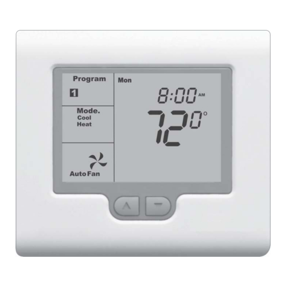
- Page 1 Installation Manual Comfort System T-32-P Universal Thermostat For Version 2.19 and 2.20...
-
Page 2: Table Of Contents
System switch functions ....6 preparation of this manual, Jackson Systems Factory default settings ....6 takes no responsibility for errors or omissions Entering the advanced installer settings menu . -
Page 3: Getting Started
THERMOSTAT LOCATION GETTING STARTED The T-32-P should be installed in a location that As with any HVAC project, careful installation is represents the ambient space temperature. Do not the key to a successful outcome. Time taken install the thermostat in an area where drafts are during the installation process will be rewarded by present, near the floor, behind doors or on an fewer call-backs. -
Page 4: Terminal Designations
1 HEAT / 1 COOL INSTALLING THE THERMOSTAT TERMINAL DESIGNATIONS Based on the T-32-P slide switch configurations, some terminals have multiple output functions . (Figure 3) HEAT 1 FAN 1 MODBUS RELAY RELAY TERMINALS COMP 1 FACTORY RELAY JUMPER LINE 24 V Power Coms... -
Page 5: Heat / 1 Cool Heat Pump
2 HEAT / 1 COOL DUAL FUEL TYPICAL SYSTEM WIRING DIAGRAMS 2 HEAT / 1 COOL HEAT PUMP FOSSIL FAN 1 MODBUS FUEL VALVE RELAY TERMINALS COMP 1 FAN 1 MODBUS RELAY HEAT VALVE RELAY TERMINALS LINE 24 V COMP 1 Switch Settings RELAY 24 V... -
Page 6: Special Instructions For Dual Fuel Applications
SYSTEM SWITCH FUNCTIONS SPECIAL INSTRUCTIONS FOR DUAL FUEL APPLICATIONS Sw1 - Fan Relay Leave Switch 1 OFF When the T-32-P is used with dual fuel systems, an (factory default). outdoor sensor is recommended for balance point control (Model T-32-S1). The sensor is wired to the Sw2 - Equipment Switch 2 sets the equipment configuration. -
Page 7: Entering The Advanced Installer Settings Menu
ENTERING THE ADVANCED INSTALLER SETTINGS MENU ENTERING THE ADVANCED INSTALLER SETTINGS MENU ADVANCED INSTALLER SETTINGS MENU The T-32-P contains factory defaults for all Advanced Symbol Default Function Installer Settings. Depending upon the user and equipment application, some settings may need to be Leave at factory default changed. -
Page 8: Tt Terminal Functions
ADVANCED INSTALLER SETTINGS MENU ADVANCED INSTALLER SETTINGS MENU Symbol Default Function Symbol Default Function Start/Stop Mode. 1.4° F differential for stage 1. (Controlled by thermostat program) SP=2 - 1.9° F differential. SS=1 - Thermostat in Start only mode SP=3 - 2.4° F differential. per call by Modbus Master. -
Page 9: Indoor Sensor Wiring
REMOTE ON/OFF OR OVERRIDE TT TERMINAL FUNCTIONS Using an external dry contact switch, the T-32-P INDOOR SENSOR WIRING can be configured to turn the thermostat off or When the T-32-S1 is used as an indoor sensor, the change the heating and cooling setpoints to a T-32-P can be configured to allow only the remote pre-programmed override value. -
Page 10: Testing Fan Operation
The T-32-P incorporates a number of time delays RESETTING THE TIME DELAYS which can be disabled during testing by setting After testing the thermostat, change CD=1 to CD=0 CD=1 in the Advanced Installer menu. After exiting in the Advanced Installer menu. This will be the menu, a wrench icon will flash on the LCD. -
Page 11: Remote Sensor Installation Instructions
18-2 thermostat cable for sensor wiring. For information regarding these features, contact Prior to wiring the sensor to the thermostat, use an Jackson Systems at 1-888-652-9663 ohm-meter or multimeter to measure the resistance of the sensor. Measure at the end of the...