Table of Contents
Advertisement
Quick Links
520 Direct Vent Indoor
and Outdoor Models
Water Heater
Model 520 Direct Vent Indoor
On-Demand Water Heater
Service Manual
520 Indoor / 520 Outdoor Service Manual
Water Heater
Model 520 Outdoor
A.O. Smith Water Products Company
500 Tennessee Waltz Parkway
Ashland City, TN 37015
Toll Free: 1-877-737-2840
1
CONFIDENTIAL
Ver. 1.00
Advertisement
Chapters
Table of Contents

Related Manuals for A.O. Smith Water Heater 520 Direct Vent Indoor


Summary of Contents for A.O. Smith Water Heater 520 Direct Vent Indoor
- Page 1 520 Direct Vent Indoor and Outdoor Models On-Demand Water Heater Service Manual Water Heater Water Heater Model 520 Outdoor Model 520 Direct Vent Indoor A.O. Smith Water Products Company 500 Tennessee Waltz Parkway Ashland City, TN 37015 Toll Free: 1-877-737-2840...
-
Page 2: Table Of Contents
CONFIDENTIAL 520 Indoor / 520 Outdoor Service Manual Ver. 1.00 Table of Contents 1. Specifications………………………………………...…...………….……………………...………………………… 3 2. Exterior view……………………...…….………………………………………………………………………………. 4 3. Interior view…………………………….……………………………………………………………………………….. 6 4. List of main components in the interior view…….………………………………………………….…… 8 5. Schematic diagram…………………………………………………………………………………………………..10 6. Wiring diagram…………………………………………………………………………………………………………. 11 7. -
Page 3: Specifications
CONFIDENTIAL 520 Indoor / 520 Outdoor Service Manual Ver. 1.00 1. Specifications of the 520 Direct Vent Indoor* and Outdoor Model 520 Direct Vent Indoor 520 Outdoor Dimensions H25.6"×W18.5"×D12.4" Weight 73 lbs. 71 lbs. 199,000 INPUT BTU/h 13,000 Combustion System Power vent Installation Direct-vent... -
Page 4: Exterior View
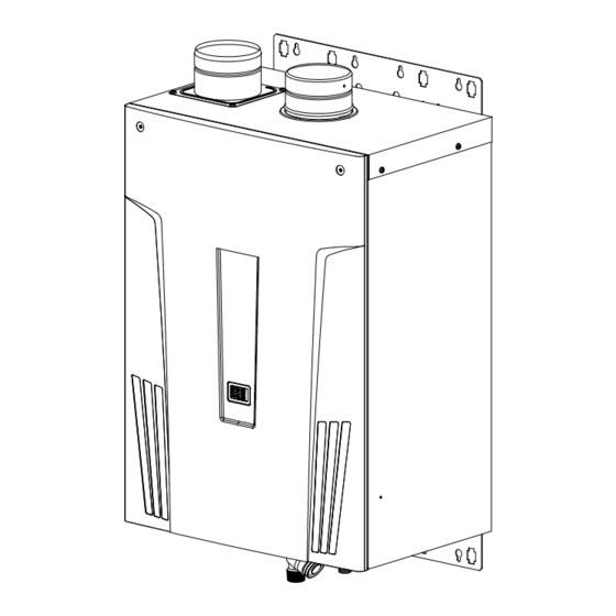
CONFIDENTIAL 520 Indoor / 520 Outdoor Service Manual Ver. 1.00 2. Exterior view 520 Indoor Front view Side view Bottom view Top view... - Page 5 CONFIDENTIAL 520 Indoor / 520 Outdoor Service Manual Ver. 1.00 520 Outdoor Front view Side view Bottom view Top view...
-
Page 6: Interior View
CONFIDENTIAL 520 Indoor / 520 Outdoor Service Manual Ver. 1.00 3. Interior view 520 Indoor... - Page 7 CONFIDENTIAL 520 Indoor / 520 Outdoor Service Manual Ver. 1.00 520 Outdoor...
-
Page 8: List Of Main Components In The Interior View
CONFIDENTIAL 520 Indoor / 520 Outdoor Service Manual Ver. 1.00 4. List of main components in the interior view Item# in Common parts Description components AOS Part # For other models diagram Manifold assembly with 319143-046 (LP model) gas valve assembly 319143-047 (NA model) Computer board 319143-126... - Page 9 CONFIDENTIAL 520 Indoor / 520 Outdoor Service Manual Ver. 1.00 Item# in Common parts Description components AOS Part # For other models diagram Outlet drain plug 319143-079 AFR rod 319143-035 310, 510, 910, 710 Flame rod 319143-035 310, 510, 910, 710 Igniter rod 319143-037 310, 510, 910, 710...
-
Page 10: Schematic Diagram
CONFIDENTIAL 520 Indoor / 520 Outdoor Service Manual Ver. 1.00 5. Schematic diagram The diagram below refers to both the 520 Indoor and 520 Outdoor. The 520 Outdoor doesn’t have the fan motor for exhaust, exhaust thermistor and hi-limit switch for exhaust. -
Page 11: Wiring Diagram
CONFIDENTIAL 520 Indoor / 520 Outdoor Service Manual Ver. 1.00 6. Wiring diagram The diagram below refers to both the 520 Indoor and 520 Outdoor. 9007603005... -
Page 12: Wiring Diagram Checkpoints For Diagnosis
CONFIDENTIAL 520 Indoor / 520 Outdoor Service Manual Ver. 1.00 7. Wiring diagram check points for diagnosis The table below applies to both the 520 Indoor and 520 Outdoor. Check- Part and Description Color of wires Normal range point White – Black (A) A, A1 100V Power supply 90 to 110 VAC... - Page 13 CONFIDENTIAL 520 Indoor / 520 Outdoor Service Manual Ver. 1.00 Check- Part and Description Color of wires Normal range point Mixing thermistor Black - Black Output thermistor Black - Black See table on p. 14 Inlet thermistor Black - Black Remote controller 11 to 25 VDC Fan motor...
-
Page 14: A) Resistance Values Of The Temperature Thermistors
CONFIDENTIAL 520 Indoor / 520 Outdoor Service Manual Ver. 1.00 8. (A) Resistance values of the temperature thermistors The 520 Indoor and 520 Outdoor use the same thermistors. Resistance values at different temperatures ºF Temperature ºC Resistance kΩ 23.76 19.08 15.43 12.56 10.28... -
Page 15: B) Resistance Values Of The Temperature Exhaust Thermistors
CONFIDENTIAL 520 Indoor / 520 Outdoor Service Manual Ver. 1.00 8. (B) Resistance values of the temperature Exhaust thermistor Only the 520 Indoor is equipped with the exhaust thermistor. Resistance values at different temperatures ºF Temperature ºC Resistance kΩ 30.04 24.12 19.50 15.87 13.00 10.71 8.87 7.39 6.19... -
Page 16: Operational Flow Chart
CONFIDENTIAL 520 Indoor / 520 Outdoor Service Manual Ver. 1.00 9. Operational flow chart The diagram below refers to both the 520 Indoor and 520 Outdoor. -
Page 17: Component Specifications
CONFIDENTIAL 520 Indoor / 520 Outdoor Service Manual Ver. 1.00 10. Component specifications 10-1. Burners……………………..………………………………….………………………………..………. 18 10-2. Gas manifold………….………………………………………………..……………………………..19 10-3. Fan motor……………………………………………………………………………………….……...… 20 10-4. Fan motor for exhaust………………………………………………………………………………. 10-5. Gas valve assembly………………..……………………….………………………………..………. 22 10-6. Flame rod………………………………………………………….………………………………………. 23 10-7. AFR rod……………………………………………………………………………………………….……. 10-8. -
Page 18: Burners
CONFIDENTIAL 520 Indoor / 520 Outdoor Service Manual Ver. 1.00 10-1. Burners Unit Part # #101 AOS Part # 319143-030 Checkpoint There are 2 types of burners in the water heater: the gas-rich burner stabilizes the flames within the combustion chamber and the air-rich burner Function produces more heat in the combustion chamber. -
Page 19: Gas Manifold
CONFIDENTIAL 520 Indoor / 520 Outdoor Service Manual Ver. 1.00 10-2. Gas manifold Included 319143-046 (LP) Unit Part # AOS Part # Checkpoint in #118 319143-047 (NG) 1. The manifold distributes gas from the gas valves to the burners. The manifold has two types of the nozzles: one type for gas-rich burners (16 Function nozzles) and the other for air-rich burners (15 nozzles) -
Page 20: Fan Motor
CONFIDENTIAL 520 Indoor / 520 Outdoor Service Manual Ver. 1.00 10-3. Fan motor Unit Part # #114 AOS Part # 319143-043 Checkpoint To provide combustion air into the combustion chamber and to exhaust flue Function gas. 1. Fan speed failure, causing abnormal sounds with or without combustion during operation. -
Page 21: Fan Motor For Exhaust
CONFIDENTIAL 520 Indoor / 520 Outdoor Service Manual Ver. 1.00 10-4. Fan motor for exhaust Unit Part # #124 AOS Part # 319143-053 Checkpoint Function To control exhaust temperature. 1. Fan speed failure, causing abnormal sounds with or without combustion during operation. -
Page 22: Gas Valve Assembly
CONFIDENTIAL 520 Indoor / 520 Outdoor Service Manual Ver. 1.00 10-5. Gas valve assembly Unit Part # Included 319143-046 (LP) AOS Part # Checkpoint C,H1 in #118 319143-047 (NA) Opens and closes the gas pathways of the water heater (main and solenoid gas valves) Function Modulates the gas flow from the gas inlet (proportional gas valve) -
Page 23: Flame Rod
CONFIDENTIAL 520 Indoor / 520 Outdoor Service Manual Ver. 1.00 10-6. Flame rod Unit Part # #106 AOS Part # 319143-035 Checkpoint To detect flames while the water heater is in operation. Function 1. Unable to detect flames when flames actually do occur Failure events 2. -
Page 24: Afr Rod
CONFIDENTIAL 520 Indoor / 520 Outdoor Service Manual Ver. 1.00 10-7. AFR rod Unit Part # #106 AOS Part # 319143-035 Checkpoint Checks flame conditions during combustion. Function When AFR rod detects unexpected flame conditions, the computer of the water heater makes adjustments in the fan motor speed to compensate. 1. -
Page 25: Heat Exchanger
CONFIDENTIAL 520 Indoor / 520 Outdoor Service Manual Ver. 1.00 10-8. Heat exchanger Unit Part # #401 319143-064 (520 Indoor) AOS Part # Checkpoint #456 319143-118 (520 Outdoor) Absorbs heat from combustion and transfer it to water through the heat Function exchanger pipes. -
Page 26: Secondary Heat Exchanger
CONFIDENTIAL 520 Indoor / 520 Outdoor Service Manual Ver. 1.00 10-9. Secondary heat exchanger Unit Part # AOS Part # 319143-108 Checkpoint Absorb latent heat from exhaust gas and transfer the water through the Function secondary heat exchanger pipes, which can improve heat efficiency of the unit by approximately 10%. -
Page 27: Flow Sensor
CONFIDENTIAL 520 Indoor / 520 Outdoor Service Manual Ver. 1.00 10-10. Flow sensor Unit Part # #429 AOS Part # 319143-092 Checkpoint Detects and measures water flow rate using a spinning impeller and magnetic Function pick-up. Unable to detect or measure any water flow rate. Failure event Effects on the water... -
Page 28: Water Control Valve
CONFIDENTIAL 520 Indoor / 520 Outdoor Service Manual Ver. 1.00 10-11. Water control valve (flow adjustment valve and bypass valve) Unit Part # #423 AOS Part # 319143-086 Checkpoint The water control valve in the water heater has three functions of water control: flow adjustment, bypass, and two-way. - Page 29 CONFIDENTIAL 520 Indoor / 520 Outdoor Service Manual Ver. 1.00 10-11. Water control valve (flow adjustment valve and bypass valve) Blue-Brown 13.0 to 16.0 VDC Color/Number Orange-Brown ON: 12.5 to 16.0 VDC OFF: 0 to 1 VDC wires Red-Brown (0° position) 1 VDC less The water control valve contains the flow adjustment valve and the bypass valve.
-
Page 30: Thermistors
CONFIDENTIAL 520 Indoor / 520 Outdoor Service Manual Ver. 1.00 10-12. Thermistors #422 (Inlet) 319143-085 (Inlet) E1 (Mixing) Unit Part # #433 (Output) AOS Part # 319143-096 (Output) Checkpoint E2 (Output) #418 (Mixing) 319143-081 (Mixing) E3 (Inlet) Measure cold/hot water temperatures in the water heater. Function Unable to properly measure water temperatures within the water heater. -
Page 31: Exhaust Thermistor
CONFIDENTIAL 520 Indoor / 520 Outdoor Service Manual Ver. 1.00 10-13. Exhaust thermistor Unit Part # #706 AOS Part # 319143-131 Checkpoint Measures the exhaust temperatures in the exhaust chamber. Function Unable to measure exhaust temperature in the exhaust chamber properly. Failure events If the thermistors fail open or short, error code appears before starting Effects on the water heater... -
Page 32: Hi-Limit Switch
CONFIDENTIAL 520 Indoor / 520 Outdoor Service Manual Ver. 1.00 10-14. Hi-limit switch Unit Part # #432 AOS Part # 319143-095 Checkpoint -Based on bi-metal thermal expansion. -Detects excessively high water temperature (more than 194˚F or 90˚C) in pipes of the heat exchanger. Function -After detection, communication between the computer board and gas valves are severed, shutting down the water heater instantly. -
Page 33: Hi-Limit Switch For Exhaust
CONFIDENTIAL 520 Indoor / 520 Outdoor Service Manual Ver. 1.00 10-15. Hi-limit switch for exhaust Unit Part # #442 AOS Part # 319143-104 Checkpoint -Based on bi-metal thermal expansion. Function -Detects excess temperature (more than 151˚F or 66˚C) of exhaust gas in the exhaust chamber. -
Page 34: Overheat Cutoff Fuse
CONFIDENTIAL 520 Indoor / 520 Outdoor Service Manual Ver. 1.00 10-16. Overheat cutoff fuse Unit Part # #404 AOS Part # 319143-067 Checkpoint -The overheat cutoff fuse contains solder with a melting point of 430˚F (221˚C). -Detects excessive temperatures within the water heater, especially around Function the heat exchanger and... -
Page 35: Freeze Protection Heaters
CONFIDENTIAL 520 Indoor / 520 Outdoor Service Manual Ver. 1.00 10-17. Freeze protection heaters #405 319143-068 #415 319143-078 Unit Part # #426 AOS Part # 319143-089 Checkpoint #453 319143-115 #454 319143-116 Prevents the heat exchanger, water valves, and water pipes within the water Function heater from freezing. -
Page 36: Computer Board
CONFIDENTIAL 520 Indoor / 520 Outdoor Service Manual Ver. 1.00 10-18. Computer board Unit Part # #701 AOS Part # 319143-126 Checkpoint Controls the functions of most of the parts in the water heater. Function Malfunctioning computer Failure events -A component(s) may not operate within the water heater. In most cases Effects on the water of computer board failure, the whole the water heater does not operate at heater if the computer... -
Page 37: Transformer
CONFIDENTIAL 520 Indoor / 520 Outdoor Service Manual Ver. 1.00 10-19. Transformer Unit Part # #702 AOS Part # 319143-127 Checkpoint A1,A2 -To transform input voltage from 120 VAC to 100 VAC. -Every electrical component of the water heater is designed to only work Function with a 100 VAC power supply, therefore, the water heater comes equipped with this transformer. -
Page 38: Igniter
CONFIDENTIAL 520 Indoor / 520 Outdoor Service Manual Ver. 1.00 10-20. Igniter Unit Part # #123 AOS Part # 319143-052 Checkpoint -To ignite the gas/air mixtures when the water heater is ready to burn gas on Function its burner surface. -The output voltage of the igniter is more than 14 kVDC. -
Page 39: Freeze Protection Thermostat
CONFIDENTIAL 520 Indoor / 520 Outdoor Service Manual Ver. 1.00 10-21. Freeze protection thermostat #704 319143-129 (In) Unit Part # AOS Part # Checkpoint #719 319143-144 (Out) Temperature detecting device which prevents the pipes within the water heater from freezing. When this device detects temperatures below 36.5˚F Function (2.5˚C) inside the water heater, power is supplied to the electric heaters to prevent the water heater from freezing. -
Page 40: Surge Box
CONFIDENTIAL 520 Indoor / 520 Outdoor Service Manual Ver. 1.00 10-22. Surge box Unit Part # #715 AOS Part # 319143-140 Checkpoint Protects the unit from high voltage and/or high electric current caused by lightning. Function There are 2 types of surge absorbers in the water heater. Surge absorber A is activated by voltage higher than 220 V, the other one is activated by voltage higher than 680 V. -
Page 41: Fault Analysis & Specifications
CONFIDENTIAL 520 Indoor / 520 Outdoor Service Manual Ver. 1.00 11. Fault Analysis & Specifications Remarks: 1. Proper range of values of voltage & resistance shown below. 2. Please refer to the wiring diagram for checkpoint positions. Remove power to the water heater when checking for continuity, disconnections, resistance values, etc. Check Natural of Fault Diagnosis... - Page 42 CONFIDENTIAL 520 Indoor / 520 Outdoor Service Manual Ver. 1.00 Natural of Fault Diagnosis Checkpoint 5 Check that the filter on the cold water inlet is clean. The hot water is not 6 Check whether or not the unit is frozen. available when a fixture 7 Check if there is enough gas in the tank.
- Page 43 CONFIDENTIAL 520 Indoor / 520 Outdoor Service Manual Ver. 1.00 Natural Diagnosis Checkpoint Fault 4 Fault of PCB in the water heater Fluctuation [1] No voltage to gas solenoid valve (SV of hot water Normal: 78 to 100 VDC between COM (blue) & #9 (green) temperature (during operation) [2] No voltage to gas solenoid valve (SV...
- Page 44 CONFIDENTIAL 520 Indoor / 520 Outdoor Service Manual Ver. 1.00 Error Code Diagnosis Checkpoint 7 Check if there is dust and lint in burner and heat exchanger, when the water heater has been installed in laundry room. 8 Check if there is grease and dirt in burner and fan motor, when the water heater has been installed in restaurant.
- Page 45 CONFIDENTIAL 520 Indoor / 520 Outdoor Service Manual Ver. 1.00 Error Code Diagnosis Checkpoint 5 Disconnected/damaged O.H.C.F. (Refer to section 10-16) V isual inspection: connection/breakage of wires. Normal: 1 Ω or less between blue & blue 6 Disconnected/damaged hi-limit switch. (Refer to section 10-14) V isual inspection: connection/breakage of wires.
- Page 46 CONFIDENTIAL 520 Indoor / 520 Outdoor Service Manual Ver. 1.00 Error Code Diagnosis Checkpoint 4 Check for soot on the flame rod [1] Clean the flame rod [2] PCB fault During operation: more than 1 μA through the flame rod wire (orange) 5 Disconnected/damaged O.H.C.F.
- Page 47 CONFIDENTIAL 520 Indoor / 520 Outdoor Service Manual Ver. 1.00 Error Code Malfunction description Cancellation method Disconnected/short-circuited exhaust thermistor Turn off the power or water supply (520 Indoor only) Diagnosis Checkpoint 1 Exhaust thermistor fault (Refer to section 10-13) V isual inspection: connection/breakage of wires and/or debris on thermistor.
- Page 48 CONFIDENTIAL 520 Indoor / 520 Outdoor Service Manual Ver. 1.00 Error Code Malfunction description Cancellation method Fault of driving circuit for main gas solenoid valve (MV, SV , SV and/or SV (The computer checks the condition of the main Turn off the power supply gas valve immediately after every operation and the conditions of the solenoid valves 6 hours after every operation)
- Page 49 CONFIDENTIAL 520 Indoor / 520 Outdoor Service Manual Ver. 1.00 Error Code Malfunction description Cancellation method Fan motor fault Turn off the power or water supply Diagnosis Checkpoint 1 PCB and fan motor fault (Refer to section 10-3 & 10-18) V isual inspection of fan motor: connection/breakage of wires or dust buildup (causing electrical shortage) Normal: 110 to 160 VDC between red &...
- Page 50 CONFIDENTIAL 520 Indoor / 520 Outdoor Service Manual Ver. 1.00 Error Code Diagnosis Checkpoint Verify fan motor speed for exhaust of the water heater using the "diagnostics mode" of the 520 models computer board or the 9007603005 temperature remote controller. See the "12-1.
- Page 51 CONFIDENTIAL 520 Indoor / 520 Outdoor Service Manual Ver. 1.00 Error Code Malfunction description Cancellation method Water control valve fault Turn off the power or water supply (Bypass valve function) Diagnosis Checkpoint 1 PCB and bypass valve fault (Refer to section 10-11 & 10-18) V isual inspection of Water control valve: connection/breakage of wires, motor drive locked due to scale buildup, and/or water leakage.
- Page 52 CONFIDENTIAL 520 Indoor / 520 Outdoor Service Manual Ver. 1.00 Error Code Malfunction description Cancellation method 1. Hi-limit switch trip / Overheat cutoff fuse compromised NOTE: When these components are compromised, Turn off the power supply the “711” error code may appear instead of the “111”...
- Page 53 CONFIDENTIAL 520 Indoor / 520 Outdoor Service Manual Ver. 1.00 Error Code Malfunction description Cancellation method Restoring proper cable connections among all the water heaters. When the Miscommunication between Parent and Child computer detects proper connections units for Easy-Link systems. among all the water heaters, "761"...
-
Page 54: Controls And Settings
CONFIDENTIAL 520 Indoor / 520 Outdoor Service Manual Ver. 1.00 12. Controls and settings 12-1. (A) Diagnosis using the computer board……….………………………………………………………………..55 12-1. (B) Diagnosis using the 9007603005…………..……….…………………………………………………………….. 56 12-2. Verifying functionality of computer board, Displaying error code history, and Clearing error code history memory…..................………... -
Page 55: A) Diagnosis Using The Computer Board
CONFIDENTIAL 520 Indoor / 520 Outdoor Service Manual Ver. 1.00 12-1. (A) Diagnosis using the computer Board Function This function offers a method for checking the information in the water heater’s troubleshooting operations without using the remote controller (9007603005). <Using this function> 1. -
Page 56: B) Diagnosis Using The 9007603005
CONFIDENTIAL 520 Indoor / 520 Outdoor Service Manual Ver. 1.00 12-1. (B) Diagnosis using the 9007603005 < Individual unit> 1. Press the "HOT" button and the "COLD" button simultaneously for “HOT” “TIME” at least 5 seconds to enter “Diagnostic mode”. “COLD”... - Page 57 CONFIDENTIAL 520 Indoor / 520 Outdoor Service Manual Ver. 1.00 < For multiple units in an Easy-Link system > 1. Press and hold the "HOT" and "COLD" buttons simultaneously for at least 5 seconds to enter “Diagnostics Mode”. 2. "0" will be displayed on the 9007603005. (See Fig. 1) 3.
- Page 58 CONFIDENTIAL 520 Indoor / 520 Outdoor Service Manual Ver. 1.00 <Description of mode numbers in “Diagnostics Mode” for individual unit> 3-digit 7-seg LED on the Remote controller (9007603005) computer board Diagnostics information Mode Mode Unit information (#1 to #4) Unit information (#1 to #4) Total operation time 0 to 999 (×100 hours) 0 to 9,999 (×10 hours)
- Page 59 CONFIDENTIAL 520 Indoor / 520 Outdoor Service Manual Ver. 1.00 3-digit 7-seg LED on the Remote controller (9007603005) computer board Diagnostics information Mode Mode Unit information (#1 to #4) Unit information (#1 to #4) Current value of Proportional 0 to 999 0 to 9,999 (×0.1mA) valve “1”...
- Page 60 CONFIDENTIAL 520 Indoor / 520 Outdoor Service Manual Ver. 1.00 <Description of mode numbers in “Diagnostics Mode” for whole unit in Easy-link system> 3-digit 7-seg LED on the Remote controller (9007603005) computer board Diagnostics information Mode Whole easy-link system Mode Whole easy-link system information (#0) information (#0)
-
Page 61: Verifying Functionality Of Computer Board, Displaying Error Code History, And Clearing Error Code History Memory
CONFIDENTIAL 520 Indoor / 520 Outdoor Service Manual Ver. 1.00 12-2. Verifying functionality of computer board, Displaying error code history, and Clearing error code history memory A. Check if the computer board works properly Check the 100 VAC power supply on the computer board. Refer to part “A” on p. 11. Check the voltage at “A”. - Page 62 CONFIDENTIAL 520 Indoor / 520 Outdoor Service Manual Ver. 1.00 B. Error code history The 520 Indoor and 520 Outdoor has an “Error-call button” on the computer board that provides two main functions. The button is located next to the dipswitches (please look at the picture to the right).
-
Page 63: Clearing The "101" And "991" Error Code
CONFIDENTIAL 520 Indoor / 520 Outdoor Service Manual Ver. 1.00 12-3. Clearing the “101” and “991” error code The “101” and “991” error codes signify imperfect (abnormal) combustion, caused by insufficient intake air and/or obstructions in the exhaust. A. If the “101” and “991” error code occurs, please check the following: 1. -
Page 64: Afr Rod Function
CONFIDENTIAL 520 Indoor / 520 Outdoor Service Manual Ver. 1.00 12-4. AFR rod function <Function> The AFR rod checks flame conditions during combustion. When the AFR rod detects unexpected flame conditions, the computer board of the 520 models adjusts the fan motor speed to ensure that air and fuel are always at a proper mixture ratio, minimizing emissions. -
Page 65: Dipswitch Settings
CONFIDENTIAL 520 Indoor / 520 Outdoor Service Manual Ver. 1.00 12-5. Dipswitch settings Right bank of dipswitches The computer board in the 520 Indoor is the same as one in the 520 Outdoor. There are two banks of dipswitches (right and left bank) on the computer board. The left bank has certain special functions as shown on the following table and generally should not need adjustment. - Page 66 CONFIDENTIAL 520 Indoor / 520 Outdoor Service Manual Ver. 1.00 The function of the left dipswitch bank Functions ON position OFF position Gas type Propane Disable Natural gas Disable (Default) Allow adjustments of fan motor speed Enable Disable (Default) (Changing the FM speed is similar to changing the manifold pressure.
-
Page 67: Assigning Unit Numbers In The Easy-Link System
CONFIDENTIAL 520 Indoor / 520 Outdoor Service Manual Ver. 1.00 12-6. Assigning unit numbers in the Easy-link system How to display the unit number Press the “Number display” button on the computer board. The 3-digit 7-seg LED will then display the assigned number for that 520 Indoor or 520 Outdoor unit for 10 sec. -
Page 68: A) On/Off Conditions: Overview
CONFIDENTIAL 520 Indoor / 520 Outdoor Service Manual Ver. 1.00 12-7. (A) ON/OFF conditions: Overview The following table shows the ON/OFF conditions of the water heater. ON/OFF Conditions The BTU requirement is more than 14,880 BTU/h Conditions needed to turn ON. The water flow rate is more than 0.5 GPM The BTU requirement is less than 11,900 BTU/h Inlet temperature is higher than the set... -
Page 69: B) On/Off Conditions: Btu Requirements
CONFIDENTIAL 520 Indoor / 520 Outdoor Service Manual Ver. 1.00 12-7. (B) ON/OFF conditions: BTU requirements A. Calculating the ON/OFF conditions of the 520 Indoor or 520 Outdoor Condition needed to turn the 520 Indoor or 520 Outdoor ON – T ) ×... -
Page 70: A) Pump Control On/Off Conditions (Only For Single And Easy-Link System)
CONFIDENTIAL 520 Indoor / 520 Outdoor Service Manual Ver. 1.00 12-8. (A) Pump control ON/OFF Conditions (Only for single and Easy-link system) To run circulation pumps efficiently and effectively, the 520 Indoor or 520 Outdoor offers four different modes of pump control. The following table shows the pump control ON/OFF conditions for different modes. -
Page 71: B) Pump Control On/Off Conditions: Btu Requirements
CONFIDENTIAL 520 Indoor / 520 Outdoor Service Manual Ver. 1.00 12-8. (B) Pump control ON/OFF conditions: BTU requirements A. Calculating the ON/OFF conditions of the 520 Indoor or 520 Outdoor Condition needed to turn the pump ON – T ) × GPM × 500 > 14,880 Condition needed to turn the pump OFF 5 minutes after activation, if the computer detects a BTU requirement of less than 18,600 BTU/h, the computer will stop the pump 90 seconds. -
Page 72: Multi-Unit System On/Off Conditions
CONFIDENTIAL 520 Indoor / 520 Outdoor Service Manual Ver. 1.00 12-9. Multi-unit system ON/OFF conditions In an Easy-Link system, the amount of 520 Indoors or 520 Outdoors called on to activate depends on the FLOW RATE SET TEMPERATURE. and the 1. -
Page 73: Operation Time For Unit Rotation
CONFIDENTIAL 520 Indoor / 520 Outdoor Service Manual Ver. 1.00 12-10. Operation time for unit rotation The unit that turns on first is whichever unit the 520 Indoor or 520 Outdoor decides is the primary unit. The priority unit will rotate when it reaches 100 ON/OFF cycles or after 12 hours of operation. NOTE: The priority unit is the unit that turns on first when there is a hot water demand. -
Page 74: Individual Unit Operation In Easy-Link System While Parent Unit Is Under Abnormal Conditions (Individual Operation Mode)
CONFIDENTIAL 520 Indoor / 520 Outdoor Service Manual Ver. 1.00 12-11. Individual unit operation in easy-link system while parent unit is under abnormal conditions (Individual operation mode) In an easy-link system, if a parent unit undergoes abnormal conditions, the 520 Indoors or 520 Outdoors can operate as individual units. -
Page 75: High Altitude Region Support Software (Fm+, Fm++ And Fm+++)
CONFIDENTIAL 520 Indoor / 520 Outdoor Service Manual Ver. 1.00 12-12. High-Altitude Region Support Functions (FM+, FM++, FM+++ and INPUT-) Using this function The high-altitude region support functions have four operation levels, with the appropriate level being set up by the installer until the abnormal sound problem is solved. -
Page 76: How To Convert Unit Of Set Temperature
CONFIDENTIAL 520 Indoor / 520 Outdoor Service Manual Ver. 1.00 12-13. How to convert unit of set temperature This function offers a method for displaying the temperature in Celsius instead of Fahrenheit. On the 520 Indoor or 520 Outdoor, changing the unit of temperature can be done simply by using the No.1 dipswitch of Light bank of dipswitches. -
Page 77: Control For Exhaust Temperature (520 Indoor Only)
CONFIDENTIAL 520 Indoor / 520 Outdoor Service Manual Ver. 1.00 12-14. Control for exhaust temperature (520 Indoor only) <Function and Purpose> The exhaust gas temperature is controlled by the exhaust fan motor. The 520 Indoor is equipped with a thermistor and hi-limit switch for detecting excess temperatures of the exhaust gas within the flue and enabling the unit to safely stop operations if needed. -
Page 78: Relay Selection For The Pump Control Connection
CONFIDENTIAL 520 Indoor / 520 Outdoor Service Manual Ver. 1.00 12-15. Relay selection for the pump control connection The maximum current capacity of the 520 Indoor or 520 Outdoor pump control connection is 1 amp. Before using any relay with the pump control, please check the specifications of that particular relay to ensure that the current value through the coil will not exceed 1 amp. -
Page 79: Alarm Port Terminal
CONFIDENTIAL 520 Indoor / 520 Outdoor Service Manual Ver. 1.00 12-16. Alarm port terminal This function is to alert end-users of any error codes that may occur by using an alarm lamp and/or the buzzer and connecting it to the 520 models computer board. When the 520 models computer detects any error codes, the alarm port terminal on the 520 models computer will activate the connected lamp or buzzer. -
Page 80: Adjusting Manifold Gas Pressure
CONFIDENTIAL 520 Indoor / 520 Outdoor Service Manual Ver. 1.00 12-17. Adjusting manifold gas pressure The manifold gas pressure on the 520 Indoor or 520 Outdoor can be adjusted by following the procedures below. Adjusting the manifold pressure can cause unexpected combustion conditions during operation, which can cause a health hazard, damage the 520 Indoor or 520 Outdoor , and/or shorten its lifespan. - Page 81 CONFIDENTIAL 520 Indoor / 520 Outdoor Service Manual Ver. 1.00 5. Press and hold down the “MIN” button on the computer board. While holding down the “MIN” button, press either the “Increase” or “Decrease” button to increase or decrease the manifold gas pressure, respectively (Figure 3).
-
Page 82: Manually Adjusting The Fan Motor Speed
CONFIDENTIAL 520 Indoor / 520 Outdoor Service Manual Ver. 1.00 12-18. Manually adjusting the fan motor speed While the FM+ and the FM++ dipswitch will automatically increase the fan speed, the fan motor speed on the 520 Indoor or 520 Outdoor can also be manually adjusted. (Refer to Section 12-5) In order to perform manual adjustments to the speed, a 9007603005 remote controller is required. - Page 83 CONFIDENTIAL 520 Indoor / 520 Outdoor Service Manual Ver. 1.00 “MAX” button “MIN” button “Increase” button NOTE: The dark square is the direction “Decrease” button the dipswitch should be set to. Figure.1 Left bank of dipswitch settings Figure.2 520 models Computer board For example;...
-
Page 84: Freeze Protection System
CONFIDENTIAL 520 Indoor / 520 Outdoor Service Manual Ver. 1.00 12-19. Freeze protection system There are two features to the 520 Indoor or 520 Outdoor freeze protection system: the automatic firing system and the ceramic heating blocks. The automatic firing system allows the 520 Indoor or 520 Outdoor to briefly fire on for about 3 seconds and the ceramic heating blocks will heat up whatever portion of the heat exchanger the blocks are strapped to. - Page 85 CONFIDENTIAL 520 Indoor / 520 Outdoor Service Manual Ver. 1.00 To sum it up in a chart: 5 minutes have elapsed Inlet thermistor Output thermistor Will automatic firing be since prior operation? temperature temperature activated? Above 46°F Above 37°F 37°F and below 46°F and above 37°F and below Ceramic heating blocks...
-
Page 86: Freeze Protection For Recirculation Systems
CONFIDENTIAL 520 Indoor / 520 Outdoor Service Manual Ver. 1.00 12-20. Freeze protection for recirculation systems The 520 Indoor or 520 Outdoor has the freeze protection function for a re-circulation system by using a pump installed in the system. Basically, this function is only ON / OFF control of the pump from the computer in the 520 Indoor or 520 Outdoor. - Page 87 CONFIDENTIAL 520 Indoor / 520 Outdoor Service Manual Ver. 1.00 <How to set the Freeze protection pump > To set the Freeze protection pump mode in 520 Indoor or 520 Outdoor, please follow the procedures below: 1. Change the dipswitch No.4 of the right bank on the computer board to the “OFF” position (Individual operation mode should be position) .
-
Page 88: Draining The Unit And Cleaning The Inlet Water Filter
CONFIDENTIAL 520 Indoor / 520 Outdoor Service Manual Ver. 1.00 12-21. Draining the unit and cleaning the inlet water filter Close the manual gas shut off valve. 2. Turn off power to the 520 Indoor or 520 Outdoor, wait a few seconds. And then turn on again. Wait 30 seconds for water valves starts to completely open. -
Page 89: Components Diagrams
CONFIDENTIAL 520 Indoor / 520 Outdoor Service Manual Ver. 1.00 13. Components diagrams Case assembly Other than the case assembly (No.15) and the front cover (No.16), all of the 520 Outdoor parts are the same as the 520 Indoor. The 520 Outdoor doesn’t have the fan motor for exhaust (No.124). 520 Indoor 520 Outdoor... - Page 90 CONFIDENTIAL 520 Indoor / 520 Outdoor Service Manual Ver. 1.00 Computer board assembly Other than Part# 719, the 520 Indoor and the 520 Outdoor share the same components. The 520 Outdoor doesn’t have exhaust thermistor assembly (No.706) exhaust fan motor wire (No.720).
- Page 91 CONFIDENTIAL 520 Indoor / 520 Outdoor Service Manual Ver. 1.00 Water way assembly Other than Part# 456, Part# 459, Part# 460 and Part# 461, the 520 Indoor and the Outdoor share the same components. The 520 Outdoor doesn’t have the hi-limit switch for exhaust (No.442) and the exhaust thermistor assembly (No.706).
-
Page 92: Parts List
CONFIDENTIAL 520 Indoor / 520 Outdoor Service Manual Ver. 1.00 14. Parts list Item # Part # Description Common parts for other models 319143-009 Case assembly (IN) 319143-010 Front cover for (IN) 319143-011 Intake air port assembly 319143-012 Brackets 319143-013 Back guard panel 319143-014 Junction box 110, 310, 510, 910, 710, 319143-015 Rubber bush... - Page 93 CONFIDENTIAL 520 Indoor / 520 Outdoor Service Manual Ver. 1.00 Item # Part # Description Common parts for other models 319143-037 Igniter rod 310, 510, 910, 710 319143-038 Rod cap 110, 310, 510, 910, 710 319143-039 High voltage ignite cable 110, 310, 510, 910 319143-040 Damper 319143-041 Urethane tube...
- Page 94 CONFIDENTIAL 520 Indoor / 520 Outdoor Service Manual Ver. 1.00 Item # Part # Description Common parts for other models 319143-062 Pan screw M4×10 319143-063 Hex head screw M4×8 319143-329 Flange gasket for fan motor 319143-206 Silicon ring 319143-064 Heat exchanger assembly (IN) 319143-065 Silicon ring 110, 310, 510, 710 319143-066 Fuse fixing plate 18...
- Page 95 CONFIDENTIAL 520 Indoor / 520 Outdoor Service Manual Ver. 1.00 Item # Part # Description Common parts for other models 319143-089 Pipe heater 120 319143-090 Pan screw M4×6 (W/Washer) 319143-091 O-ring P15 FKM 319143-092 Flow sensor 910, 710 319143-093 Hot pipe 319143-094 Joint elbow 319143-095 Hi-limit switch 510, 910, 710...
- Page 96 CONFIDENTIAL 520 Indoor / 520 Outdoor Service Manual Ver. 1.00 Item # Part # Description Common parts for other models 319143-118 Heat exchanger assembly (Out) 319143-119 O-ring P3 FKM 319143-120 Secondary heat exchanger drain plug 319143-121 Exhaust port 319143-122 Exhaust chamber assembly 319143-123 Secondary heat exchanger plate 319143-124 Heater fixing plate 20 319143-125 Heater fixing plate 16...
-
Page 97: Revisions
CONFIDENTIAL 520 Indoor / 520 Outdoor Service Manual Ver. 1.00 15. Revisions Version Description of changes Date 1.00 First edition 11/01/10...