Yamaha YZF-R1 Owner's Manual
Hide thumbs
Also See for YZF-R1:
- Service manual (808 pages) ,
- Owner's manual (130 pages) ,
- Manual (82 pages)

Related Manuals for Yamaha YZF-R1


Summary of Contents for Yamaha YZF-R1
- Page 1 Read this manual carefully before operating this vehicle. OWNER’S MANUAL YZF-R1 2SG-28199-E0...
- Page 2 Read this manual carefully before operating this vehicle. This manual should stay with this vehicle if it is sold. YAMAHA MOTOR ELECTRONICS CO., LTD. 1450-6, Mori, Mori-machi, Shuchi-gun, Shizuoka-ken, 437-0292 Japan DECLARATION of CONFORMITY Company: YAMAHA MOTOR ELECTRONICS CO., LTD. Address: 1450-6, Mori, Mori-Machi, Shuchi-gun, Shizuoka-Ken, 437-0292 Japan Hereby declare that the product: Kind of equipment: IMMOBILIZER...
- Page 3 Yamaha a reputation for dependability. Please take the time to read this manual thoroughly, so as to enjoy all advantages of your YZF-R1. The Owner’s Manual does not only instruct you in how to operate, inspect and maintain your motorcycle, but also in how to safeguard yourself and others from trouble and injury.
-
Page 4: Important Manual Information
IMPORTANT MANUAL INFORMATION EAU10134 Particularly important information is distinguished in this manual by the following notations: This is the safety alert symbol. It is used to alert you to potential personal injury hazards. Obey all safety messages that follow this symbol to avoid possible injury or death. - Page 5 IMPORTANT MANUAL INFORMATION EAU10201 YZF-R1 OWNER’S MANUAL ©2013 by Yamaha Motor Co., Ltd. 1st edition, May 2013 All rights reserved. Any reprinting or unauthorized use without the written permission of Yamaha Motor Co., Ltd. is expressly prohibited. Printed in Japan.
-
Page 6: Table Of Contents
TABLE OF CONTENTS SAFETY INFORMATION ....1-1 Adjusting the front fork ....3-31 Checking the engine idling Adjusting the shock absorber speed ........6-17 DESCRIPTION ........2-1 assembly........3-33 Checking the throttle grip free Left view ......... 2-1 Luggage strap holders ....3-35 play.......... - Page 7 TABLE OF CONTENTS Checking the front fork....6-30 Checking the steering ....6-31 Checking the wheel bearings ..6-31 Battery ...........6-32 Replacing the fuses.......6-33 Replacing a headlight bulb....6-35 Tail/brake light.......6-36 Replacing a turn signal light bulb ..........6-36 Replacing the license plate light bulb ..........6-37 Auxiliary light .........6-38 Supporting the motorcycle....6-38 Troubleshooting ......6-39...
-
Page 8: Safety Information
SAFETY INFORMATION Never operate a motorcycle with- pears to be very effective in reduc- EAU1028B out proper training or instruction. ing the chance of this type of Take a training course. Beginners accident. Be a Responsible Owner should receive training from a cer- Therefore: As the vehicle’s owner, you are re- tified instructor. - Page 9 SAFETY INFORMATION Many accidents involve inexperi- • Always signal before turning or Protective Apparel enced operators. In fact, many op- changing lanes. Make sure that The majority of fatalities from motorcy- erators who have been involved in other motorists can see you. cle accidents are the result of head in- ...
- Page 10 SAFETY INFORMATION Do not run engine outdoors where Avoid Carbon Monoxide Poisoning When loading within this weight limit, All engine exhaust contains carbon engine exhaust can be drawn into keep the following in mind: Cargo and accessory weight monoxide, a deadly gas.
- Page 11 Yamaha accessories, which are avail- performed to your vehicle that change lightweight as possible and able only from a Yamaha dealer, have any of the vehicle’s design or operation should be kept to a minimum. been designed, tested, and approved characteristics can put you and others •...
- Page 12 SAFETY INFORMATION Check that the fuel cock (if operator and may limit control ability, therefore, such accesso- equipped) is in the “OFF” position ries are not recommended. and that there are no fuel leaks. Use caution when adding electri- ...
-
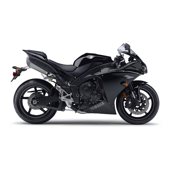
Page 13: Description
DESCRIPTION EAU10411 Left view 4,5,6 12 11 1. Front fork spring preload adjusting bolt (page 3-31) 8. Shock absorber assembly compression damping force adjusting bolt (for slow compression damping) (page 3-33) 2. Front fork compression damping force adjusting screw (page 3-31) 9. -
Page 14: Right View
DESCRIPTION EAU10421 Right view 1,2,3 4 1. Storage compartment (page 3-29) 9. Radiator cap (page 6-14) 2. Luggage strap holder (page 3-35) 10.Engine oil filler cap (page 6-11) 3. Helmet holder (page 3-29) 11.Engine oil level check window (page 6-11) 4. -
Page 15: Controls And Instruments
DESCRIPTION EAU10431 Controls and instruments 1. Clutch lever (page 3-20) 9. Brake lever (page 3-21) 2. Left handlebar switches (page 3-18) 3. Main switch/steering lock (page 3-2) 4. Multi-function meter unit (page 3-8) 5. Hazard switch (page 3-19) 6. Front brake fluid reservoir (page 6-24) 7. -
Page 16: Instrument And Control Functions
Do not expose any key to exces- cess, take the vehicle along with all three keys to a Yamaha dealer to have sively high temperatures. Do not place any key close to them re-registered. Do not use the key with the red bow for driving. -
Page 17: Main Switch/Steering Lock
INSTRUMENT AND CONTROL FUNCTIONS Keep other immobilizer system EAU10473 EAU10551 Main switch/steering lock keys away from the main switch All electrical circuits are supplied with as they may cause signal inter- power, the meter lighting, taillight, li- ference. cense plate light and auxiliary lights come on, and the engine can be start- ed. - Page 18 INSTRUMENT AND CONTROL FUNCTIONS To unlock the steering EAU10685 ECA11021 LOCK NOTICE The steering is locked, and all electrical Do not use the parking position for systems are off. The key can be re- an extended length of time, other- moved.
-
Page 19: Indicator Lights And Warning Lights
Yamaha dealer check the electrical flashes when the turn signal switch is circuit. pushed to the left or right. Even if the oil level is sufficient, the EAU11061 Neutral indicator light “... - Page 20 “ON”, initially when the key is turned to “ON”, or if the warning light remains on, have or if the warning light remains on, have a Yamaha dealer check the electrical a Yamaha dealer check the electrical circuit. circuit.
- Page 21 INSTRUMENT AND CONTROL FUNCTIONS Display Conditions What to do Under 40 °C Message “Lo” is displayed. OK. Go ahead with riding. (Under 104 °F) 40–116 °C Coolant temperature is dis- OK. Go ahead with riding. (104–242 °F) played. Stop the vehicle and allow it to idle until Coolant temperature flash- Above 116 °C the coolant temperature goes down.
- Page 22 “ON”, or if the and the lights by following the proce- This warning light comes on or flashes light remains on, have a Yamaha dealer dures under “Resetting” on page 3-23. if a problem is detected in the electrical check the electrical circuit.
-
Page 23: Multi-Function Meter Unit
an odometer initially when the key is turned to “ON”, two tripmeters (which show the or if the indicator light remains on, have a Yamaha dealer check the electrical distance traveled since they were circuit. last set to zero) 1. - Page 24 INSTRUMENT AND CONTROL FUNCTIONS a self-diagnosis device Tachometer Clock and stopwatch modes a display brightness and shift tim- ing indicator light control mode Be sure to turn the key to “ON” be- fore using the “SELECT” and “RE- SET”...
- Page 25 INSTRUMENT AND CONTROL FUNCTIONS To display the stopwatch 3. Push the start switch “ ” or “RE- Push the “SELECT” button again To change the display to the stop- SET” button to display the final to select the speed mode; “F-20” watch mode, push the “SELECT”...
- Page 26 INSTRUMENT AND CONTROL FUNCTIONS Odometer, tripmeter, instantaneous fuel consumption and average fuel For the UK only: To switch between the reverse consumption modes Push the “SELECT” button to switch chronological order mode and the the display between the odometer speed mode, push the “SELECT”...
- Page 27 INSTRUMENT AND CONTROL FUNCTIONS Instantaneous fuel consumption mode To switch between the instantaneous TRIP F → km/L or L/100 km → AVE_ fuel consumption displays, push the _._ km/L or AVE_ _._ L/100 km → ODO “SELECT” button for one second when →...
- Page 28 INSTRUMENT AND CONTROL FUNCTIONS “AVE_ _._ km/L”: The average dis- Transmission gear display This display indicates which drive tance that can be traveled on 1.0 L mode has been selected: “STD”, “A” or of fuel is shown. “B”. For more details on the modes ...
- Page 29 INSTRUMENT AND CONTROL FUNCTIONS Traction control system mode dis- ECA10022 NOTICE play Even if the air intake temperature Do not continue to operate the en- is set to be displayed, the coolant gine if it is overheating. temperature warning light comes on if the engine overheats.
- Page 30 If the display indicates any error codes, following steps. Yamaha dealer and have the stan- note the code number, and then have 1. Turn the key to “OFF”. dard keys re-registered.
- Page 31 INSTRUMENT AND CONTROL FUNCTIONS 3. Turn the key to “ON”, and then re- This function allows you to se- 5. Push the “SELECT” button to con- lease the “SELECT” button after lect the engine speed at which firm the selected brightness level. five seconds.
- Page 32 INSTRUMENT AND CONTROL FUNCTIONS 2. Push the “SELECT” button to con- To set the shift timing indicator light To adjust the shift timing indicator light firm the selected indicator light ac- deactivation function brightness 1. Push the “RESET” button to select tivity.
-
Page 33: D-Mode (Drive Mode)
INSTRUMENT AND CONTROL FUNCTIONS This mode allows the rider to enjoy EAU47633 EAU1234E D-mode (drive mode) Handlebar switches smooth and sporty drivability from the D-mode is an electronically controlled low-speed range to the high-speed Left engine performance system with three range. - Page 34 INSTRUMENT AND CONTROL FUNCTIONS Right EAU12401 EAU12661 Dimmer switch “ ” Engine stop switch “ ” Set this switch to “ ” for the high Set this switch to “ ” before starting beam and to “ ” for the low beam. the engine.
-
Page 35: Clutch Lever
INSTRUMENT AND CONTROL FUNCTIONS The hazard lights are used in case of an EAU12821 Clutch lever emergency or to warn other drivers The mode is set to “STD” by de- when your vehicle is stopped where it fault. The “STD” mode resets might be a traffic hazard. -
Page 36: Shift Pedal
INSTRUMENT AND CONTROL FUNCTIONS be sure to set it by aligning a groove on EAU12872 EAU33854 Shift pedal Brake lever the adjusting knob with the “ ” mark on the brake lever. 1. Shift pedal 1. Brake lever 2. Brake lever position adjusting knob The shift pedal is located on the left 3. -
Page 37: Brake Pedal
INSTRUMENT AND CONTROL FUNCTIONS EAU12942 EAU51862 Brake pedal Traction control system The traction control may engage The traction control system helps when the vehicle travels over a maintain traction when accelerating. If bump. sensors detect that the rear wheel is ... - Page 38 INSTRUMENT AND CONTROL FUNCTIONS “TCS” modes 2 through 6 provide Setting the traction control system for more traction control system EWA16071 WARNING assist. Mode 6 provides the most traction control system assist. Changing settings while riding can “TCS OFF” mode turns the trac- distract the operator.
-
Page 39: Fuel Tank Cap
1/4 turn clockwise. The lock will be still be ridden; however, have a released and the fuel tank cap can be Yamaha dealer check the motorcycle opened. as soon as possible. ECA17732 NOTICE To close the fuel tank cap ... -
Page 40: Fuel
INSTRUMENT AND CONTROL FUNCTIONS EAU13222 Fuel The fuel tank cap cannot be closed un- Make sure there is sufficient gasoline in less the key is in the lock. In addition, the tank. the key cannot be removed if the cap is EWA10882 WARNING not properly closed and locked. -
Page 41: Fuel Tank Breather Hose And Overflow Hose
Make sure that the end of each Your Yamaha engine has been de- hose is positioned outside of the signed to use premium unleaded gas- cowling. -
Page 42: Catalytic Converter
INSTRUMENT AND CONTROL FUNCTIONS EAU13434 ECA10702 EAU47272 Catalytic converter Seats NOTICE This model is equipped with a catalytic Use only unleaded gasoline. The use converter in the exhaust system. Passenger seat of leaded gasoline will cause unre- EWA10863 pairable damage to the catalytic WARNING To remove the passenger seat converter. - Page 43 INSTRUMENT AND CONTROL FUNCTIONS 1. Projection 1. Bolt 1. Projection 2. Seat holder 2. Seat holder 2. Remove the key. 2. Install the bolts with the hexagon wrench. Rider seat 3. Insert the hexagon wrench back into its holder on the passenger To remove the rider seat seat.
-
Page 44: Helmet Holder
INSTRUMENT AND CONTROL FUNCTIONS EAU47531 EAU14464 Helmet holder Storage compartment To release the helmet from the hel- 1. Helmet holder 1. Storage compartment met holder Remove the passenger seat, remove The helmet holder is located on the The storage compartment is located the helmet from the helmet holder, and bottom of the passenger seat. -
Page 45: Rider Footrest Position
Have a Yamaha dealer ad- narrow spaces. Fold the mirrors back just the position of the rider footrests. to their original position before riding. -
Page 46: Adjusting The Front Fork
INSTRUMENT AND CONTROL FUNCTIONS load thereby soften EAU47622 Spring preload setting: Adjusting the front fork suspension, turn the adjusting bolt on Minimum (soft): EWA14671 each fork leg in direction (b). WARNING Standard: Always adjust the spring preload on Maximum (hard): both fork legs equally, otherwise poor handling and loss of stability may result. - Page 47 INSTRUMENT AND CONTROL FUNCTIONS compression damping force and there- by soften the compression damping, Although the total number of clicks of a turn the adjusting screw in direction (b). damping force adjusting mechanism may not exactly match the above Be sure to perform this adjustment on specifications due to small differences the left front fork leg.
-
Page 48: Adjusting The Shock Absorber Assembly
INSTRUMENT AND CONTROL FUNCTIONS EAU51891 Adjusting the shock absorber assembly This shock absorber assembly is equipped with a spring preload adjust- ing screw, a rebound damping force adjusting screw, a compression damp- ing force adjusting bolt (for fast com- pression damping) and a compression damping force adjusting bolt (for slow 1. - Page 49 INSTRUMENT AND CONTROL FUNCTIONS Compression damping force Compression damping setting (for fast compression damping): To obtain a precise adjustment, it is Minimum (soft): advisable to check the actual total 4 turn(s) in direction (b)* number of clicks or turns of each Standard: damping force adjusting mechanism.
-
Page 50: Luggage Strap Holders
The sidestand is located on the left sembly yourself. Take the shock side of the frame. Raise the sidestand absorber assembly to a Yamaha or lower it with your foot while holding dealer for any service. the vehicle upright. -
Page 51: Ignition Circuit Cut-Off System
INSTRUMENT AND CONTROL FUNCTIONS this system regularly and have a EAU44893 Ignition circuit cut-off system Yamaha dealer repair it if it does not The ignition circuit cut-off system function properly. (comprising the sidestand switch, clutch switch and neutral switch) has the following functions. - Page 52 INSTRUMENT AND CONTROL FUNCTIONS WARNING With the engine turned off: 1. Move the sidestand down. If a malfunction is noted, have a Yamaha 2. Make sure that the engine stop switch is set to “ ”. dealer check the system before riding.
-
Page 53: For Your Safety - Pre-Operation Checks
• If necessary, add recommended coolant to specified level. 6-14 Coolant • Check cooling system for leakage. • Check operation. • If soft or spongy, have Yamaha dealer bleed hydraulic system. • Check brake pads for wear. Front brake • Replace if necessary. 6-23, 6-24 •... - Page 54 • Make sure that operation is smooth. • Check throttle grip free play. 6-18, 6-28 Throttle grip • If necessary, have Yamaha dealer adjust throttle grip free play and lubricate ca- ble and grip housing. • Make sure that operation is smooth. Control cables 6-27 •...
- Page 55 • Tighten if necessary. Instruments, lights, signals • Check operation. — and switches • Correct if necessary. • Check operation of ignition circuit cut-off system. Sidestand switch 3-35 • If system is not working correctly, have Yamaha dealer check vehicle.
-
Page 56: Operation And Important Riding Points
a lean angle sensor to stop the en- The transmission is in the neutral understand, ask your Yamaha dealer. gine in case of a turnover. In this EWA10272 position. -
Page 57: Shifting
The neutral indi- quate lubrication may damage cator light should come on. If not, the transmission. 1. Shift pedal ask a Yamaha dealer to check the Always use the clutch while 2. Neutral position electrical circuit. changing gears to avoid dam- Shifting gears lets you control the 3. -
Page 58: Tips For Reducing Fuel Consumption
Yamaha dealer check the vehi- to the correct operating clearances. gine. cle. During this period, prolonged full-throt- ... -
Page 59: Parking
OPERATION AND IMPORTANT RIDING POINTS EAU17214 Parking When parking, stop the engine, and then remove the key from the main switch. EWA10312 WARNING Since the engine and exhaust system can become very hot, park in a place where pedestri- ans or children are not likely to touch them and be burned. -
Page 60: Periodic Maintenance And Adjustment
To avoid possible burns, let tivities incorrectly may increase brake components cool before your risk of injury or death during touching them. service or while using the vehicle. If you are not familiar with vehicle ser- vice, have a Yamaha dealer perform service. -
Page 61: Owner's Tool Kit
If you do not have the tools or experi- ence required for a particular job, have a Yamaha dealer perform it for you. -
Page 62: Periodic Maintenance Chart For The Emission Control System
From 50000 km (30000 mi), repeat the maintenance intervals starting from 10000 km (6000 mi). Items marked with an asterisk should be performed by a Yamaha dealer as they require special tools, data and tech- nical skills. -
Page 63: General Maintenance And Lubrication Chart
PERIODIC MAINTENANCE AND ADJUSTMENT EAU1770G General maintenance and lubrication chart ODOMETER READING ANNUAL ITEM CHECK OR MAINTENANCE JOB 1000 km 10000 km 20000 km 30000 km 40000 km CHECK (600 mi) (6000 mi) (12000 mi) (18000 mi) (24000 mi) √ 1 * Air filter element •... - Page 64 PERIODIC MAINTENANCE AND ADJUSTMENT ODOMETER READING ANNUAL ITEM CHECK OR MAINTENANCE JOB 1000 km 10000 km 20000 km 30000 km 40000 km CHECK (600 mi) (6000 mi) (12000 mi) (18000 mi) (24000 mi) • Check operation and for exces- √ √...
- Page 65 PERIODIC MAINTENANCE AND ADJUSTMENT ODOMETER READING ANNUAL ITEM CHECK OR MAINTENANCE JOB 1000 km 10000 km 20000 km 30000 km 40000 km CHECK (600 mi) (6000 mi) (12000 mi) (18000 mi) (24000 mi) • Check operation. √ √ √ √ √...
- Page 66 PERIODIC MAINTENANCE AND ADJUSTMENT ODOMETER READING ANNUAL ITEM CHECK OR MAINTENANCE JOB 1000 km 10000 km 20000 km 30000 km 40000 km CHECK (600 mi) (6000 mi) (12000 mi) (18000 mi) (24000 mi) • Check operation. • Check throttle grip free play, and √...
-
Page 67: Removing And Installing Cowlings
PERIODIC MAINTENANCE AND ADJUSTMENT EAU18782 Removing and installing cowl- ings The cowlings shown need to be re- moved to perform some of the mainte- nance jobs described in this chapter. Refer to this section each time a cowl- ing needs to be removed and installed. 1. - Page 68 PERIODIC MAINTENANCE AND ADJUSTMENT 1. Turn signal light lead coupler 1. Slot 1. Cowling C 2. Projection 2. Quick fastener screw To install a cowling 3. Install the quick fasteners and the 3. Slide the cowling forward to un- 1. Connect the turn signal light lead quick fastener screws.
-
Page 69: Checking The Spark Plugs
3. Install cowling A or B. checked periodically, preferably by a Yamaha dealer. Since heat and depos- its will cause any spark plug to slowly erode, they should be removed and checked in accordance with the peri- odic maintenance and lubrication chart. -
Page 70: Engine Oil And Oil Filter Cartridge
PERIODIC MAINTENANCE AND ADJUSTMENT EAU47282 Specified spark plug: Engine oil and oil filter car- NGK/LMAR9E-J If a torque wrench is not available tridge when installing a spark plug, a good The engine oil level should be checked Before installing a spark plug, the estimate of the correct torque is 1/4–... -
Page 71: To Change Engine Oil
4. Engine oil filler cap An oil filter wrench is available at a 1. Engine oil drain bolt 4. If the engine oil is at or below the Yamaha dealer. 2. Gasket minimum level mark, add suffi- cient oil of the recommended type 6. - Page 72 PERIODIC MAINTENANCE AND ADJUSTMENT Recommended engine oil: See page 8-1. Oil quantity: Without oil filter cartridge replace- ment: 3.73 L (3.94 US qt, 3.28 Imp.qt) With oil filter cartridge replacement: 3.93 L (4.15 US qt, 3.46 Imp.qt) 1. O-ring 1. Torque wrench Be sure to wipe off spilled oil on any parts after the engine and exhaust sys- Tightening torque:...
-
Page 73: Coolant
Yamaha dealer check the level varies with engine tem- ing the bolts, remove the coolant the vehicle. -
Page 74: To Change The Coolant
[EWA10382] corrosion. If water has been added to the coolant, have a Yamaha dealer check the anti- freeze content of the coolant as soon as possible, otherwise the effectiveness of the coolant will 1. Coolant reservoir cap be reduced. - Page 75 PERIODIC MAINTENANCE AND ADJUSTMENT 6. Remove the coolant reservoir cov- 7. Remove the coolant reservoir by 11. Pour the recommended coolant er by removing the bolts, and then removing the bolts, and then turn into the reservoir to the maximum remove the coolant reservoir cap.
-
Page 76: Air Filter Element
16. Install the coolant reservoir cover Have a Yamaha dealer replace the air Yamaha dealer. by installing the bolts. filter element. 17. Install the cowlings. -
Page 77: Checking The Throttle Grip Free Play
Therefore, it must be adjusted by a Yamaha dealer is essential to maintain the tires in good at the intervals specified in the periodic condition at all times and replace them maintenance and lubrication chart. - Page 78 250 kPa (2.50 kgf/cm², 36 psi) or glass fragments in it, or if the side- surface must first be “broken Rear: wall is cracked, have a Yamaha dealer in” for it to develop its optimal 290 kPa (2.90 kgf/cm², 42 psi) replace the tire immediately.
- Page 79 WARNING ed below have been approved for this Tires age, even if they have not been model by Yamaha Motor Co., Ltd. This motorcycle is fitted with super- used or have only been used occasion- high-speed tires. Note the following ally.
-
Page 80: Cast Wheels
If any damage is found, have conditions. a Yamaha dealer replace the wheel. Do not attempt even the smallest repair to the wheel. A de- 1. Clutch lever free play adjusting bolt formed or cracked wheel must be 2. -
Page 81: Checking The Brake Lever Free Play
There should be no free play at the play, turn the adjusting nut in di- brake lever end. If there is free play, rection (b). have a Yamaha dealer inspect the brake system. EWA14212 WARNING A soft or spongy feeling in the brake lever can indicate the presence of air in the hydraulic system. -
Page 82: Brake Light Switches
EAU22274 EAU22393 Brake light switches Checking the front and rear most appears, have a Yamaha dealer brake pads replace the brake pads as a set. The front and rear brake pads must be checked for wear at the intervals spec-... -
Page 83: Checking The Brake Fluid Level
PERIODIC MAINTENANCE AND ADJUSTMENT Use only the specified brake flu- Rear brake EAU22582 Checking the brake fluid level id; otherwise, the rubber seals Before riding, check that the brake fluid may deteriorate, causing leak- is above the minimum level mark. age. -
Page 84: Changing The Brake Fluid
EAU22733 EAU22762 Changing the brake fluid Drive chain slack Yamaha dealer check the cause before Have a Yamaha dealer change the The drive chain slack should be further riding. brake fluid at the intervals specified in... - Page 85 EAU34318 To adjust the drive chain slack 1 2 3 4 Consult a Yamaha dealer before ad- justing the drive chain slack. 1. Loosen the axle nut and the lock- nut on each side of the swingarm. 2. To tighten the drive chain, turn the...
-
Page 86: Cleaning And Lubricating The Drive Chain
If a cable is wet areas. Service the drive chain as damaged or does not move smoothly, follows. have a Yamaha dealer check or re- place it. WARNING! Damage to the ECA10584 NOTICE outer housing of cables may result... -
Page 87: Checking And Lubricating The Throttle Grip And Cable
In pedals should be checked before each addition, the cable should be lubricat- ride, and the pedal pivots should be lu- ed by a Yamaha dealer at the intervals bricated if necessary. specified in the periodic maintenance Brake pedal chart. -
Page 88: Checking And Lubricating The Brake And Clutch Levers
EWA10732 Clutch lever WARNING If the sidestand does not move up and down smoothly, have a Yamaha dealer check or repair it. Otherwise, the sidestand could contact the ground and distract the operator, re- sulting in a possible loss of control. -
Page 89: Lubricating The Swingarm Pivots
The swingarm pivots must be lubricat- face and hold it in an upright posi- fork does not operate smoothly, ed by a Yamaha dealer at the intervals tion. WARNING! To avoid injury, have a Yamaha dealer check or re- specified in the periodic maintenance securely support the vehicle so pair it. -
Page 90: Checking The Steering
Yamaha dealer ward and backward. If any free check the wheel bearings. play can be felt, have a Yamaha dealer check or repair the steer- ing. 6-31... -
Page 91: Battery
6. Negative battery lead (black) To charge the battery • EYES: Flush with water for 15 Have a Yamaha dealer charge the bat- minutes and seek prompt The battery is located under the rider tery as soon as possible if it seems to medical attention. -
Page 92: Replacing The Fuses
PERIODIC MAINTENANCE AND ADJUSTMENT 4. After installation, make sure that ECA16522 EAU49824 Replacing the fuses NOTICE the battery leads are properly con- The main fuse, the fuel injection sys- To charge a VRLA (Valve Regulated nected to the battery terminals. tem fuse, and the fuse boxes, which Lead Acid) battery, a special (con- ECA16531... - Page 93 To access the fuel injection system age to the electrical system and 4. If the fuse immediately blows fuse, remove the starter relay cover by possibly a fire. again, have a Yamaha dealer [EWA15132] pulling it upward. check the electrical system. 6-34...
-
Page 94: Replacing A Headlight Bulb
PERIODIC MAINTENANCE AND ADJUSTMENT EAU39014 Replacing a headlight bulb This model is equipped with halogen bulb headlights. If a headlight bulb burns out, replace it as follows. ECA10651 NOTICE Take care not to damage the follow- ing parts: Headlight bulb 1. -
Page 95: Tail/Brake Light
1. Remove the turn signal light lens 7. Have a Yamaha dealer adjust the If the tail/brake light does not come on, by removing the screw. headlight beam if necessary. have a Yamaha dealer check it. -
Page 96: Replacing The License Plate Light Bulb
PERIODIC MAINTENANCE AND ADJUSTMENT EAU24314 Replacing the license plate light bulb 1. Remove the license plate light unit by removing the screws. 1. Turn signal light bulb 1. License plate light bulb 2. License plate light bulb socket 3. Insert a new bulb into the socket, 3. -
Page 97: Auxiliary Light
1. Stabilize the rear of the motorcy- If an auxiliary light does not come on, cle by using a motorcycle stand have a Yamaha dealer check it. or, if an additional motorcycle stand is not available, by placing a jack under the frame in front of the rear wheel. -
Page 98: Troubleshooting
The following troubleshooting charts represent quick and easy procedures for checking these vital systems your- self. However, should your motorcycle require any repair, take it to a Yamaha dealer, whose skilled technicians have the necessary tools, experience, and know-how to service the motorcycle properly. -
Page 99: Troubleshooting Charts
Remove the spark plugs and check the electrodes. The engine does not start. Have a Yamaha dealer check the vehicle. Check the compression. 4. Compression The engine does not start. There is compression. - Page 100 Start the engine. If the engine overheats again, have a The coolant level Yamaha dealer check and repair the cooling system. is OK. If coolant is not available, tap water can be temporarily used instead, provided that it is changed to the recommended cool- ant as soon as possible.
-
Page 101: Motorcycle Care And Storage
Some models are equipped with matte colored finished parts. Be ble. Rust and corrosion can develop Cleaning sure to consult a Yamaha dealer for even if high-quality components are ECA15093 NOTICE used. A rusty exhaust pipe may go un-... - Page 102 For additional during winter are extremely corrosive For motorcycles equipped with cleaning, use Yamaha Windshield in combination with water, carry out Cleaner or another high-quality wind- a windshield: Do not use strong the following steps after each ride in shield cleaner.
- Page 103 MOTORCYCLE CARE AND STORAGE Note that the thermally induced using such cleaners, test an area of the EWA11132 WARNING windshield which does not affect your discoloring of the portion of the visibility and which cannot be easily exhaust pipe leading into the tita- Contaminants on the brakes or tires recognized.
-
Page 104: Storage
2. Fill up the fuel tank and add fuel EAU26204 Storage stabilizer (if available) to prevent Consult a Yamaha dealer for ad- the fuel tank from rusting and the vice on what products to use. Short-term fuel from deteriorating. - Page 105 MOTORCYCLE CARE AND STORAGE e. Remove the spark plug caps from the spark plugs, and then Make any necessary repairs before install the spark plugs and the storing the motorcycle. spark plug caps. 4. Lubricate all control cables and the pivoting points of all levers and pedals as well as of the side- stand/centerstand.
-
Page 106: Specifications
SPECIFICATIONS Dimensions: Engine oil: Fuel: Overall length: Recommended brand: Recommended fuel: 2070 mm (81.5 in) YAMALUBE Premium unleaded gasoline (Gasohol (E10) Overall width: Type: acceptable) 715 mm (28.1 in) SAE 10W-40, 10W-50, 15W-40, 20W-40 or Fuel tank capacity: Overall height: 20W-50 18.0 L (4.76 US gal, 3.96 Imp.gal) 1130 mm (44.5 in) - Page 107 SPECIFICATIONS 2nd: Manufacturer/model: Rim size: 2.063 (33/16) DUNLOP/Qualifier II 17M/C x MT6.00 3rd: Loading: Front brake: 1.762 (37/21) Maximum load: Type: 4th: 189 kg (417 lb) Dual disc brake 1.522 (35/23) (Total weight of rider, passenger, cargo Operation: 5th: and accessories) Right hand operation 1.364 (30/22) Tire air pressure (measured on cold...
- Page 108 SPECIFICATIONS Charging system: Fuel level warning light: AC magneto Battery: Coolant temperature warning light: Model: Engine trouble warning light: YTZ10S Voltage, capacity: Immobilizer system indicator light: 12 V, 8.6 Ah Headlight: Shift timing indicator light: Bulb type: Halogen bulb Bulb voltage, wattage × quantity: Traction control system indicator/warning light: Headlight:...
-
Page 109: Consumer Information
Record the vehicle identification num- ber and model label information in the spaces provided below for assistance when ordering spare parts from a Yamaha dealer or for reference in case the vehicle is stolen. VEHICLE IDENTIFICATION NUMBER: 1. Vehicle identification number 1. - Page 110 INDEX Engine trouble warning light....3-7 Model label ..........9-1 Multi-function meter unit......3-8 Air filter element ........6-17 Auxiliary light.........6-38 Front and rear brake pads, checking ... 6-23 Front fork, adjusting ......3-31 Neutral indicator light......3-4 Front fork, checking ......6-30 Battery ..........6-32 Fuel............
- Page 111 INDEX Throttle grip and cable, checking and lubricating........... 6-28 Throttle grip free play, checking... 6-18 Tires ............6-18 Tool kit............ 6-2 Traction control system......3-22 Traction control system indicator/ warning light ......... 3-7 Traction control system switch .... 3-19 Troubleshooting........6-39 Troubleshooting charts......
- Page 114 Original instructions PRINTED ON RECYCLED PAPER PRINTED IN JAPAN 2013.06-0.3×1 CR...