Table of Contents

Related Manuals for Universal Audio Apollo 16 mkII


Summary of Contents for Universal Audio Apollo 16 mkII
- Page 1 H I G H - R E S O L U T I O N I N T E R F A C E with Realtime UAD Processing Apollo 16 mkII Hardware Manual Manual Version 150702 Customer Service & Technical Support:...
-
Page 2: A Letter From Bill Putnam Jr
In many ways, the Apollo family of audio interface products represent the best examples of what Universal Audio has stood for over its long history; from UA’s original founding in the 1950s by my father, through our current vision of delivering the best of both analog and digital audio technologies. -
Page 3: Table Of Contents
A Letter from Bill Putnam Jr..............2 Introduction ..................4 What is Apollo 16 mkII? ..................4 Apollo 16 mkII Features ..................5 About Apollo 16 Documentation ................7 Web Documentation ................... 8 Technical Support .................... -
Page 4: Introduction
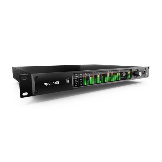
Introduction What is Apollo 16 mkII? Thunderbolt Audio Interface with QUAD Processing The new Apollo 16 is an elegant update to UA’s premium audio interface — delivering enhanced sound with the tone, feel, and flow of analog recording. Perfect for professional studios, this 18 x 20 Thunderbolt interface offers twice the analog connectivity of the Apollo 8/8p, making it ideal for pairing with mixing consoles and outboard processors. -
Page 5: Apollo 16 Mkii Features
• Two channels of AES/EBU digital I/O with optional sample rate conversion on input • Front panel pre-fader metering of analog signal input or output levels • Two Thunderbolt 2 ports for daisy-chaining other Thunderbolt devices Apollo 16 mkII Hardware Manual Introduction... - Page 6 Console application: • Analog-style control interface for realtime monitoring and tracking • Enables Realtime UAD Processing with UAD plug-ins • Remote control of Apollo 16 mkII features and functionality • Virtual I/O for routing DAW tracks through Console Console Recall plug-in: •...
-
Page 7: About Apollo 16 Documentation
The features and functionality of all individual UAD Powered Plug-Ins is detailed in the UAD Plug-Ins Manual. Refer to this document to learn about the operation, controls, and user interface of each UAD plug-in that is developed by Universal Audio. Direct Developer Plug-Ins UAD Powered Plug-Ins includes plug-ins created by our Direct Developer partners. -
Page 8: Web Documentation
Apollo Support Page The latest technical information for Apollo is posted on the Universal Audio website. The Apollo Thunderbolt support page contains updated, late-breaking information that is not available in other publications. Please visit this page for the latest news: •... -
Page 9: Technical Support
Technical Support Universal Audio provides free customer support to all registered Apollo 16 users. Support specialists are available to assist you via email and telephone during normal business hours, which are from 9 AM to 5 PM, Monday through Friday, Pacific Standard Time. -
Page 10: Front Panel
88.2 METER I/O METER 176.4 Apollo 16 mkII front panel elements (1) Meter This switch determines whether the Channel Level Meters (#4) are displaying input levels or output levels. Pressing the switch toggles the state of the channel meters and the Meter Indicators (#2). - Page 11 The dB values of the meter LEDs are indicated between the meters for channels 4 & 5 and 12 & 13. “0” indicates a level of 0 dBFS. When digital clipping occurs (when 0 dBFS is exceeded), the red “C” (clip) LED illuminates. Apollo 16 mkII Hardware Manual Front Panel...
- Page 12 1 – 16 at the output of the D/A converters. (5) Power Indicator (UA Logo) The Universal Audio logo illuminates when the external power supply is properly connected to an AC outlet and the power input on the rear of the unit, and the POWER switch (#9) is in the up position.
- Page 13 Monitor Level knob. This indicator is after the Monitor Level control (post fader). It indicates relative levels only and is not calibrated to specific dB values. Apollo 16 mkII Hardware Manual Front Panel...
- Page 14 This switch applies power to Apollo 16. When the unit is powered on, the Universal Audio logo (#5) is illuminated. The external power supply must be properly connected for this switch to function. Apollo 16 mkII Hardware Manual Front Panel...
-
Page 15: Rear Panel
The Line Outputs can be configured in adjacent pairs to use -10 dBV or +4 dBu reference levels. This function is configured in the Hardware panel within the Console Settings window. Apollo 16 mkII Hardware Manual Rear Panel... - Page 16 For example, if Apollo 16 is the last “slave” unit at the end of a clock chain (when Apollo 16’s word clock out port is not used), termination should be active. Apollo 16 mkII Hardware Manual Rear Panel...
- Page 17 Console application, the AES/EBU signal is converted to match Apollo 16’s sample rate. Note: When Apollo 16 is set to use AES/EBU as the master clock source, sample rate conversion is inactive. Apollo 16 mkII Hardware Manual Rear Panel...
- Page 18 Thunderbolt peripheral devices. Apollo 16 must be powered on for the daisy-chained peripheral to receive Thunderbolt bus power. (11) MADI Optical Ports The MADI I/O ports are unused and do not transmit or receive audio. Apollo 16 mkII Hardware Manual Rear Panel...
-
Page 19: Installation & Configuration
Thunderbolt in a multiple-unit configuration. For complete details about multi-unit cascading, refer to the Apollo Software Manual. UA Support Videos Many informational videos are available online to help you get started with Apollo 16: • www.uaudio.com/support/thunderbolt Apollo 16 mkII Hardware Manual Installation & Configuration... -
Page 20: Interconnections
• Apollo 16 is a Thunderbolt 2 device. Thunderbolt 2 technology is designed for backwards compatibility with Thunderbolt 1. • Apollo 16 can be connected to Mac computers and other devices that have Thun- derbolt 1 ports or Thunderbolt 2 ports. Apollo 16 mkII Hardware Manual Interconnections... -
Page 21: Typical Setup
LINE OUT 9-16 LINE IN 9-16 PUSH LINE OUT 1-8 LINE IN 1-8 UNIVERSAL AUDIO, INC. DB25 Audio Snakes Thunderbolt To Outboard Gear/Console From Outboard Gear/Console Line Level Inputs Line Level Outputs Typical Apollo 16 connections Apollo 16 mkII Hardware Manual Interconnections... -
Page 22: Apollo Expanded: Multi-Unit Wiring
• Do not connect more than one Thunderbolt cable between thev same two devices (the Thunderbolt protocol is bidirectional). • Do not interconnect any Word Clock, FireWire, ADAT, or MADI ports between any Apollo units. Apollo 16 mkII Hardware Manual Interconnections... -
Page 23: Specifications
Simultaneous D/A conversion 18 channels Analog Round-Trip Latency 1.1 milliseconds @ 96 kHz sample rate Analog Round-Trip Latency with up to four serial 1.1 milliseconds @ 96 kHz sample rate UAD plug-ins via Console application (continued) Apollo 16 mkII Hardware Manual Specifications... - Page 24 XLR Male Dynamic Range 124 dB (A–weighting) Signal-to-Noise Ratio 123 dB (A–weighting) Total Harmonic Distortion + Noise –117 dBFS Stereo Level Balance ±0.01 dB Output Impedance 100 Ohms Maximum Output Level +20.2 dBu (continued) Apollo 16 mkII Hardware Manual Specifications...
- Page 25 Shipping Weight (with box & accessories) 18 pounds Weight (bare unit) 8.7 pounds Package Contents Apollo 16 mkII Audio Interface Unit External Power Supply AC Power Cable (IEC) Getting Started URL Card Set of (4) Rack-Mount Screws Apollo 16 mkII Hardware Manual...
-
Page 26: Hardware Block Diagram
Hardware Block Diagram Apollo 16 mkII Hardware Manual Hardware Block Diagram... -
Page 27: Db25 Wiring
Ground – No Connect 3, 11 5, 13 Cold 8, 16 Cold 3, 11 Ground 4, 12 7, 15 2, 10 Cold 4, 12 Ground 7, 15 Ground 1, 9 1, 9 Ground Apollo 16 mkII Hardware Manual DB25 Wiring... -
Page 28: Troubleshooting
2. Press and hold the PREAMP, LOW CUT, and POLARITY controls 3. Power on Apollo 16 while continuing to hold all three controls 4. After all front panel LEDs flash rapidly (after several seconds), release the controls Apollo 16 mkII Hardware Manual Troubleshooting... -
Page 29: Notices
The unit has been dropped, or the enclosure damaged. Servicing – The user should not attempt to service the unit beyond that described in the operating instructions. All other servicing should be referred to qualified service personnel. Apollo 16 mkII Hardware Manual Notices... -
Page 30: Warranty
Warranty Universal Audio provides a warranty on all hardware products. To learn more, please visit www.uaudio.com/support/warranty.html or contact Technical Support. This limited warranty gives you specific legal rights. You may also have other rights which vary by state or country. - Page 31 Audio, Inc. makes no warranties of any kind with regard to this manual, including, but not limited to, the implied warranties of merchantability and fitness for a particular purpose. Universal Audio, Inc. shall not be liable for errors contained herein or direct, indirect, special, incidental, or consequential damages in connection with the furnishing, performance, or use of this material.
- Page 32 Universal Audio, Inc. 4585 Scotts Valley Drive Scotts Valley, CA 95066 USA Customer Service & Technical Support: USA Toll-Free: +1-877-698-2834 International: +1-831-440-1176 www.uaudio.com...