Table of Contents
Advertisement
Advertisement
Table of Contents

Related Manuals for Navtex SNX - 300

Summary of Contents for Navtex SNX - 300
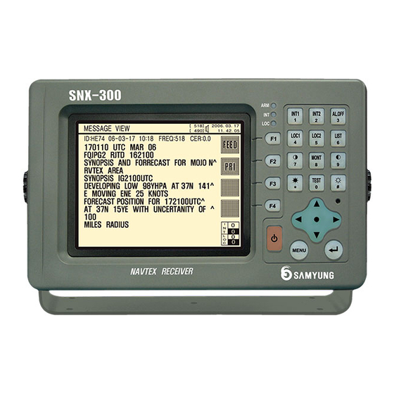
- Page 1 NAVTEX RECEIVER FOR GMDSS INSTRUCTION MANUAL SNX - 300 SAMYUNGENC CO.,LTD.
-
Page 2: Table Of Contents
6.1.1. Installation Place ...................... 21 6.1.2. Installation Sequence and Method ................21 6.2. Antenna Installation ......................21 6.2.1. Installation Place ...................... 21 6.2.2. Installation Sequence and Method ................21 CHAPTER 7. NEIGHBORING NAVTEX BROADCASTING TIMES ......... 22 CHAPTER 8. Supported interface sentences ..............25... - Page 3 8.1. IEC61097-6 ........................25 8.2. INS Signal......................... 28 CHAPTER 9. PACKING LISTS ..................29 CHAPTER 10. BLOCK DIAGRAM ..................30 CHAPTER 11. EXTERNAL DRAWING ................31...
-
Page 4: Chapter 1. Overview
NAVTEX is an abbreviation for Navigational Telex and it is a Telex-broadcasting system of the coast stations worldwide. NAVTEX of the coast stations broadcasts not only the defined ID, but also all the information on navigational warnings, weather warnings, SAR and other marine warnings for navigational safety of those vessels equipped with NAVTEX Receiver in the coasts. -
Page 5: Transmission Mode
1.2.3. Transmission Mode According to M.625-3 of ITU-R Recommendations, as NAVTEX broadcasting employs 5 Bit Code as ITA No.2 Code System (that is used for international telegraphic transactions by CCITT Recommendations F.1), only 32 characters are available. As it is impossible to display Text, Figures, Marks, Shift Signals only with 32 codes, the system allocates the conversion signals and the figure conversion to Shift Signals and additionally allocates 26 codes. -
Page 6: Transmitted Message Type
) - Serial numbers from 01 to 99 are given in NAVTEX Message. NAVTEX Coordinating Station gives these serial numbers. As a special figure, “00” is used only for significant texts such as rescue and it is unconditionally displayed on LCD screen. In case NAVTEX receives any message with this kind of special figure, it is designed to always print out whatever message it is. -
Page 7: Chapter 2. Generals Of System
It does not store any message that has more than 33% error rate of received letters, or that fails to display in a normal way. 2.2. System Composition Model Q’ty Remark NAVTEX Receiver SNX-300 1 EA ANTENNA (Active) SAN-300/SAN-518 1 EA... -
Page 8: Requirement On Receiving And Display
2.3. Requirement on Receiving and Display It prints out receiving message less than 4% error rate and ID (B1B2B3B4) are stored in the memory to prevent out duplicate message in next receiving. If the error rate of receiving message is at 33% (For over 5 sec.), stop receiving and do not save the message on memory. -
Page 9: Chapter 3. Specifications
② Receiving Modulation : F1B ③ Sensitivity : 2uV e.m.f. (50 ohms), 4% error rate or less ④ Antenna input : 50 ohms for NAVTEX antenna 3.2. DISPLAY SECTION ① Type of display : 5.7-inch STN Blue LCD, 320×240 dots ② Back-light : For LCD and key board ③... -
Page 10: Chapter 4. Led & Button
CHAPTER 4. LED & BUTTON 4.1. Front Panel 4.2. LED & Buzzer A buzzer function of a display device is for users to operate it with convenient as it takes place “Beep” sounds whenever each buttons were pressed. Besides, it is designed for the users to recognize “alarm warning” easily as the function was distributed to the buzzers when the Alarm Warning happens. -
Page 11: Button Explanation
4.3. Button Explanation FUNCTION OF BUTTONS HOW TO USE It shows numeral input keys of special <([@ characters, Numeric and Alphabet. The relative numeric & characters are displayed whenever pressing Alphabet and numeral keys. PQRS WXYZ =+/- ---- !?& It is a button to move to right, left, up and down and also possible to be used on cursor’s movement. -
Page 12: Chapter 5 How To Operate
Chapter 5 How to operate 5.0. System Menu Tree < STATION SELECTION > [1] MENUAL SET INT [2] MENUAL SET LOC [3] INITIAL CHANNEL INT [4] INITIAL CHANNEL LOC < MESSAGE SELECTION > [1] MENUAL SET INT [2] MENUAL SET LOC [3] A.B.L ALARM SET [4] INITIAL CHANNEL INT [5] INITIAL CHANNEL LOC... -
Page 13: Station Selection
Manual mode. Transmitting station can be automatically selected according to the distance between the own ship and NAVTEX transmitting station. At the automatic mode, navigation information from outside of ship should be inputted. At the manual mode, operator can select the wanted transmitting station. -
Page 14: Message Selection
5.2. Message Selection It shows category of receiving character defined by IMO RESOLUTION, and selection can be done between receiving and rejection. But, Type A,B.D,L defined at RESOLUTION can not be excluded. [ENT] [2] MESSAGE SELECTION SNX-300 [518] [ 490] 10: 06. 02 MAIN MENU LIST >>... - Page 15 Selection of [3] A.B.L ALARM SET can set ON/OFF of A.B.L alarm. SNX-300 [518] [ 490] 10: 06. 02 <<< MESSAGE SELECTION >>> [1] MENUAL SET INT [2] MENUAL SET LOC A.B.L ALARM SET [3] A.B.L ALARM SET ALARM : A B L [4] INITIAL CHANNEL INT CH INT : [ ON]...
-
Page 16: Message History
MESSAGE VIEW (F1) Print out the ID : VA57 05-10-25 16:53 Size:60 Cer:0% current screen. 152310 UTC APRIL 1999 KOREA NAVTEX/NAVY SOURCE// ROUTINE : (F3)Attach the AIR FIRING/ selected ID TAG AIR FIRING FOR 2300Z TO 1000Z DAILY FROM 17TH TO 23RD MAY IN THE SOUTHWARD SEA... - Page 17 How to use SORT key SNX-300 [518] [ 490] 10: 06. 02 (F1) Set up SORT NO ID DATA TIME SIZE FREQ TAG UP/DOWN 1 VA57 05-10-25 16:53.39 60 518 2 EF01 05-10-25 16:51.39 2K 518 3 EF02 05-10-25 16:52.39 2K 518 SORT LIST 4 EF03 05-10-25 16:53.39 2K 518 5 EF04 05-10-25 16:54.39 2K 518...
-
Page 18: User Setting
Ln 0 Ls 0 ① RECEIVE NOTIFY : Using [ENT]key, user can monitor NAVTEX audio by BUZZER when it is ② PRINTER : When it is set to be AUTO, the received message can be print out automatically, while it is set to be MANUAL, user can select and print out. -
Page 19: System Hw Setting
5.5 SYSTEM HW SETTING. It is a function to set the Hardware related items. SNX-300 [518] [ 490] 10: 06. 02 << USER SETTING >> [1] DIMMER AND CONTRAST [2] 490/4209 SELECT [ 490 ] [3] LCD REVERSE [ OFF] [4] PRINTER SPEED [5] INS SPEED [6] NMEA SPEED... -
Page 20: System Diagnostics
5.6 SYSTEM DIAGNOSTICS. This is a function to do diagnose test such as components test, program version test, display function test, LED test, receiving channel test and printer test if printer is connected. It displays “OK” if there is no “ERROR”, otherwise it displays “ERROR”. SNX-300 [518] [ 490] 10: 06. -
Page 21: Fact Manual
5.7 FACT MANUAL SNX-300 [518] [ 490] 10: 06. 02 <<< FACT MANUAL >>> [1] ERASE ALL [2] DEFAULT FACT LOAD [3] RF INT TUNING [4] RF LOC TUNING EXIT In 0 Is 0 Ln 0 Ls 0 ① ERASE ALL : To erase all the received message. ②... -
Page 22: Chapter 6. Installation & Troubleshooting
Fix firmly a mounting bracket on the desk or wall to be installed. After Navtex receiver is pushed in the mounting bracket, adjust the angles and spin the screws on the knobs right and left for better adjustment. -
Page 23: Chapter 7. Neighboring Navtex Broadcasting Times
CHAPTER 7. NEIGHBORING NAVTEX BROADCASTING TIMES Nation Local Time UTC Time Station Mark Republic of 00:30 15:30 Chukpyun Korea Republic of 00:40 15:40 Pyonsan Korea Russia 01:00 16:00 Bladivostok Russia 16:00 01:00 Lholmsk Japan 17:00 02:00 Naha Japan 17:10 02:10... - Page 24 Nation Local Time UTC Time Station Mark Republic of 08:30 15:30 Chukpyun Korea Republic of 08:40 15:40 Pyonsan Korea Russia 09:00 16:00 Bladivostok Russia 16:00 09:10 Lholmsk Japan 01:00 10:00 Naha Japan 01:10 10:10 Moji Japan 01:20 10:20 Yokohama Japan 01:30 10:30 Otaru...
- Page 25 Nation Local Time UTC Time Station Mark Republic of 16:30 07:30 Chukpyun Korea Republic of 16:40 07:40 Pyonsan Korea Russia 17:00 08:00 Bladivostok Russia 08:10 17:10 Lholmsk Japan 09:00 18:00 Naha Japan 09:10 18:10 Moji Japan 09:20 18:20 Yokohama Japan 09:30 18:30 Otaru...
-
Page 26: Chapter 8. Supported Interface Sentences
(this applies to fields 4 through 12). NOTE 2 The sequential message identifier provides a unique identifier for each NAVTEX message represented by a group of sentences. Though the message code (field 4) contains a NAVTEX message serial number, there are special cases when the message serial number is set to 00 and has a different meaning or when the same message code can occur more than once. - Page 27 The example below shows a typical message received by the Navtex receiver with 3 bad characters (‘*’): <start of example> ZCZC IE69================================== ISSUED ON SATURDAY 06 JANUARY 2001. INSHORE WATERS FORECAST TO 12 MILES OFFSHORE FROM 1700 UT* TO 0500 UTC.
- Page 28 When another device (for example an INS) wishes to set one or more of the bit masks it sends one or more NRM sentences to the NAVTEX receiver. When another device wishes to determine the current values of the bit masks it sends a query sentence to the NAVTEX receiver as follows: $--CRQ,NRM*hh<CR><LF>...
-
Page 29: Ins Signal
8.2. INS Signal. This equipment can receive navigation data in IEC 61162-1 Ed2/2 format. ① 490KHz INS transmitting ID REJECT default value $NVNMK,490,05555555,0AAAAAAA*35 $NVNMK,490,0AAAAAAA,05555555*35 ② 518KHz INS transmitting ID REJCT default value $NVNMK,518,05555555,0AAAAAAA*34 $NVNMK,518,0AAAAAAA,05555555*34 ③ Request on message transmit on 518 KHZ starting “AAXX” ID. ④... -
Page 30: Chapter 9. Packing Lists
CHAPTER 9. PACKING LISTS... -
Page 31: Chapter 10. Block Diagram
CHAPTER 10. BLOCK DIAGRAM... -
Page 32: Chapter 11. External Drawing
CHAPTER 11. EXTERNAL DRAWING...