Advertisement
Table of Contents
SERVICE MANUAL
Ver 1.0 1999. 02
Dolby noise reduction manufactured under license
from Dolby Laboratories Licensing Corporation.
"DOLBY" and the double-D symbol a are trade-
marks of Dolby Laboratories Licensing Corporation.
MICROFILM
WM-EX570
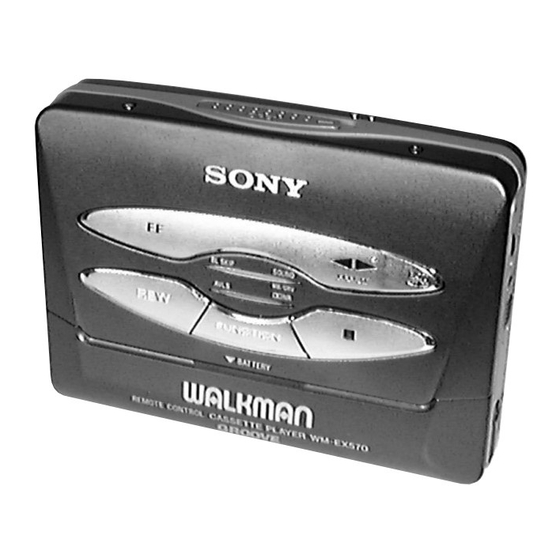
Photo: Black model
Model Name Using Similar Mechanism
Tape Transport Mechanism Type
SPECIFICATIONS
AEP Model
E Model
Tourist Model
NEW
MT-WMEX550-125
CASSETTE PLAYER
Advertisement
Table of Contents

Related Manuals for Sony WM-EX570


Summary of Contents for Sony WM-EX570
- Page 1 WM-EX570 SERVICE MANUAL AEP Model E Model Ver 1.0 1999. 02 Tourist Model Photo: Black model Dolby noise reduction manufactured under license Model Name Using Similar Mechanism from Dolby Laboratories Licensing Corporation. Tape Transport Mechanism Type MT-WMEX550-125 “DOLBY” and the double-D symbol a are trade- marks of Dolby Laboratories Licensing Corporation.
-
Page 2: Table Of Contents
OPERATION. REPLACE THESE COMPONENTS WITH • Never reuse a disconnected chip component. SONY PARTS WHOSE PART NUMBERS APPEAR AS • Notice that the minus side of a tantalum capacitor may be dam- SHOWN IN THIS MANUAL OR IN SUPPLEMENTS PUB- aged by heat. -
Page 3: Servicing Notes
SECTION 1 SERVICING NOTES This set detects the rotation of GEAR (S) using the PH701 (photo 1. Setting reflector). The PH701 is mounted on the MAIN board, and there- 1) Refer to “3. DISASSEMBLY”, and remove the cabinet and fore the GEAR cannot be detected with the MAIN board removed. open the MAIN board. - Page 4 Lever (SW) Rotation system Rotation system during PLAY. gear (NR) (REV: right side/ gear (REEL) FWD: left side) lever (SW) gear (REEL) (S side) (T side) gear (TB) gear (S) motor pulley gear (TA) side F gear (Y) clutch assy (M) side R senter flywheel (R) assy...
-
Page 5: General
SECTION 2 This section is extracted from instruction manual. GENERAL – 5 –... -
Page 6: Disassembly
SECTION 3 DISASSEMBLY • This set can be disassembled in the order shown below. Case Assy Lid Assy, Ornament Assy Belt Cassette Main Board, Holder Note for Installation Head, Magnetic Motor (Capstan/Reel) (M901) Note: Follow the disassembly procedure in the numerical order given. LID ASSY, CASSETTE 2 screw 1 Open the cassette lid assy... - Page 7 CASE ASSY 3 case assy 1 two screws (M1.4 × 2.2) 2 two claws 1 two screws (M1.4 × 2.2) ORNAMENT ASSY 2 Push to the direction of the arrow A , 4 Remove the reel ornament to direction of the arrow B . remove the claw of knob (OPEN).
- Page 8 BELT 1 belt HOLDER 2 screw 4 holder 3 two claws 1 Remove two solders of battery terminal. – 8 –...
- Page 9 3 three screws MAIN BOARD 1 Remove four solders of motor. 1 Remove two 2 flexible board solders of plunger solenoid. (CN301) 3 screw (M1.4 × 1.6) 4 MAIN board NOTE FOR INSTALLATION • MAIN BOARD On installation MAIN board adjust the S702 and lever (SW) S702 lever (SW)
- Page 10 MOTOR (CAPSTAN/REEL) (M901) 1 two screws (M1.4) 2 Remove the motor (M901) to direction of the arrow. HEAD, MAGNETIC 1 two pinch levers 2 screw 5 two screws (M1.4 × 1.6) (M1.4 × 7.2) 4 flexible board (CN301) 3 bracket assy 6 head, magnetic (HP901) –...
-
Page 11: Mechanical Adjustments
WM-EX570 SECTION 4 SECTION 5 SECTION 6 MECHANICAL ADJUSTMENTS ELECTRICAL ADJUSTMENTS DIAGRAMS • SIGNAL PATH PRECAUTION PRECAUTION 6-1. BLOCK DIAGRAM RIPPLE FILTER : PLAYBACK BATT B+ Q304 1. Clean the following parts with a denatured-alcohol-moistened 1. Specified voltage : 1.3 V (DC) swab: 2. -
Page 13: Schematic Diagram
WM-EX570 6-3. SCHEMATIC DIAGRAM • See page 20 for Waveforms, and See page 21 for IC Block Diagrams. Note on Schematic Diagram: • All capacitors are in µF unless otherwise noted. pF: µµF 50 WV or less are not indicated except for electrolytics and tantalums. - Page 14 • Waveforms • IC Block Diagrams IC601 MM1279XVBE IC301 TA2072AF 1 IC701 #• (PHOTO IN) 5 Q504 Base 500 mV/DIV, 50 ms/DIV 200 mV/DIV, 500 µs/DIV 42 41 40 39 38 1.4 Vp-p 0.6 Vp-p PRE DRIVER MOTIVE CONTROL VREF CIRCUIT BASS BOOST...
-
Page 15: Ic Pin Function Description
6-4. IC PIN FUNCTION DESCRIPTION • MAIN BOARD IC701 MSM6576-83GS-K (SYSTEM CONTROLLER) Pin No. Pin Name Description The output terminal for the control signal to start the motor M.CTL Turn the motor when set to “H” The output terminal for selecting the rotating direction of the motor M.DIR Turn the motor counterclockwise when set to “H”, and clockwise when set to “L”... - Page 16 Pin No. Pin Name Description — Power supply terminal (+1.5V) BOOST CTL Bass-boost on/off control signal output to the TA2072AF (IC301) MB/GRV CTL MEGA BASS/GROOVE selection signal output to the TA2072AF (IC301) LOAD CTL Load control signal output terminal AVLS (Automatic Volume Limiter System) on/off control signal output to the TA2072AF AVLS CTL (IC301) AMP CTL...
-
Page 17: Exploded Views
SECTION 7 EXPLODED VIEWS NOTE: • -XX and -X mean standardized parts, so they • Items marked “*” are not stocked since they • Abbreviation may have some difference from the original are seldom required for routine service. Some : East European model one. - Page 18 (2) MAIN BOARD SECTION not supplied HP901 S901 not supplied J801 Ref. No. Part No. Description Remark Ref. No. Part No. Description Remark 3-009-669-01 TERMINAL (+), BATTERY X-3374-438-1 BRACKET ASSY (EXCEPT JE) 3-375-114-11 SCREW 3-009-667-01 SPRING, TENTION 3-009-670-01 TERMINAL (-), BATTERY 3-011-277-01 COVER (B) (Y), MD 3-009-675-01 HOLDER 3-019-716-01 SCREW (M1.4), P LOCK ACE (EXCEPT JE)
- Page 19 (3) MECHANISM DECK SECTION (MT-WMEX550-125) M901 PM901 not supplied not supplied 104 103 Ref. No. Part No. Description Remark Ref. No. Part No. Description Remark X-3374-094-1 CHASSIS (S) ASSY (Y) (JE) 3-932-724-21 WASHER X-3374-440-1 CHASSIS ASSY (J2) (EXCEPT JE) 3-386-694-21 WASHER 3-007-457-01 SPRING (TEN), TENSION X-3372-852-1 FLYWHEEL (N) ASSY (JE) 3-010-954-01 SPRING (BT), COMPRESSION...
-
Page 20: Electrical Parts List
SECTION 8 MAIN ELECTRICAL PARTS LIST NOTE: • Due to standardization, replacements in the • Items marked “*” are not stocked since they The components identified by mark ! or dotted line with mark are seldom required for routine service. parts list may be different from the parts speci- ! are critical for safety. - Page 21 MAIN Ref. No. Part No. Description Remark Ref. No. Part No. Description Remark C703 1-115-156-11 CERAMIC CHIP < PHOTO REFLECTOR > C704 1-135-180-21 TANTALUM CHIP 3.3uF 6.3V PH701 8-719-988-15 PHOTO REFLECTOR PR-11-C C705 1-164-156-11 CERAMIC CHIP 0.1uF C706 1-164-156-11 CERAMIC CHIP 0.1uF <...
- Page 22 WM-EX570 MAIN Ref. No. Part No. Description Remark Ref. No. Part No. Description Remark R214 1-216-840-11 METAL CHIP 1/16W S706 1-692-453-11 SWITCH, KEY BOARD (FF) R215 1-216-793-11 RES, CHIP 1/16W S707 1-692-453-11 SWITCH, KEY BOARD (REW) R301 1-218-891-11 RES, CHIP 0.5%...