Makita 5007F Technical Information
Makita 5007f; 5007fk; 5007fa; 5007fak circular saw
Hide thumbs
Also See for 5007F:
- Instruction manual (29 pages) ,
- Instruction manual (21 pages) ,
- Instruction manual (17 pages)
Advertisement
Quick Links
Download this manual
See also:
Instruction Manual
T
ECHNICAL INFORMATION
Models No.
Description
C
ONCEPTION AND MAIN APPLICATIONS
For increasing MAKITA's share in the circular saw
market in North America, 5007F and 5007FA series models
have been developed.
They are taking over the 5007NB's feature that the large
base plate is providing easy cuttin work.
And added brief benefits and features are as follows.
* Equipped with light for easy tracing the cutting line
in the shadow.
* The continuous rating ampere has been increased to
15.0 A with 120V.
* Model 5007FA is equipped with electric brake for
quick stop.
The variations of these models are listed below.
Model No.
Electric brake
5007F
5007FK
5007FA
5007FAK
S
pecification
Model No.
Voltage (V)
5007F
5007FA
Model No.
No load speed : rpm.= min.
Diameter : mm (")
Size of blade
Arbor : mm (")
Max.cutting
capacities : mm (")
Electric brake
Protection from electric shock
Net weight : Kg (lbs.)
Cord length : m (ft)
S
tandard equipment
* T.C.T. Saw blade 185mm (7-1/4") ......................... 1 pc.
* Rip fence (Guide rule) ............................................. 1 pc.
* Wrench ................................................................... 1 pc.
* Plastic carrying case ............................................... 1 pc. (only for Model 5007FK and 5007FAK)
< Note > The standard equipment for the tool shown may differ from country to country.
O
ptional accessories
* Various Saw blades
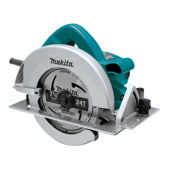
5007F, 5007FA
185mm (7-1/4") Circular Saw
Plastic carrying case
No
No
No
Yes
Yes
No
Yes
Yes
Current (A)
120
15.0
120
15.0
5007F
-1
at 0°
at 45°
No
by double insulation
H-1
H-2
Continuous Rating (W)
Cycle (Hz)
Input
AC/DC
1,600
50/60
1,600
5007FA
5,800
185 (7-1/4)
15.88 (5/8)
60 (2-3/8)
46 (1-3/4)
Yes
4.8 (10.6)
2.5 (8.2)
L-2
W-2
L-1
Dimensions : mm ( " )
Width ( W-1 )
170 (6-11/16)
Width ( W-2 )
233 (9-1/8)
Height ( H-1 )
180 (7-1/8)
245 (9-5/8)
Height ( H-2 )
Length ( L-1 )
290 (11-3/8)
305 (12 )
Length ( L-2 )
Output
900
900
PRODUCT
P 1 / 12
W-1
Max.
Output(W)
2,000
2,000
Advertisement

Related Manuals for Makita 5007F


Summary of Contents for Makita 5007F
- Page 1 185mm (7-1/4") Circular Saw ONCEPTION AND MAIN APPLICATIONS For increasing MAKITA's share in the circular saw market in North America, 5007F and 5007FA series models have been developed. They are taking over the 5007NB's feature that the large base plate is providing easy cuttin work.
-
Page 2: Features And Benefits
P 2 / 12 eatures and benefits Easy replacing saw blade 5007F, 5007FA thanks to the flat rear of motor housing. Switch for light Light (LED) for easy tracing cutting line in the shadow Model 5007FA is equipped Higher continuous rating ampere : 15.0 A with electric brake. - Page 3 < 1 > Lubrication Put 6g of MAKITA grease N. No.1 into gear case portion of blade case as illustrated in Fig. 1. Also put the same one on the leaf spring of shaft lock which is sliding on blade case as illustrated in Fig.
- Page 4 P 4 / 12 epair ( 3 ) Assemble new base plate to the saw unit by fastening angular guide with 4 pcs. of countersunk head screws M5 x 12 as illustrated in Fig. 4. Assemble cap square neck bolt M8 x 24 by screwing it from the inside of blade case through the depth guide. See Fig.
- Page 5 P 5 / 12 epair ( 4 ) Assemble safety cover by holding with retaining ring S-42. Assemble tension spring 4. (Hitch the end of tension spring on safety cover, and another end on blade case.) Assemble rubber sleeve to blade case by screwing it with pan head screw M6 x 20. <...
- Page 6 P 6 / 12 epair ( 2 ) Take off 3 pcs. of pan head screws M5 x 50, then motor housing can be separated from blade case as illustrated in Fig. 7. Armature can be separated from motor housing together with shaft lock as illustrated in Fig. 7 A. Motor housing Shaft lock Armature...
- Page 7 P 7 / 12 epair < 3 > Replacing motor housing ( 1 ) After taking off brush holder caps and carbon brushes, remove pan head screw M5 and hex lock nut M5 - 8 in order to separate motor housing from base plate as illustrated in Fig. 10. And then, separate motor housing form blade case by unscrewing 3 pcs.
- Page 8 P 8 / 13 epair < 5 > Replacing bearing box ( 1 ) For easy disassembling adjust the cutting depth to the minimum level by pulling base plate down. And then, separate safety cover from blade case by removing retaining ring S-42, tension spring 4, pan head screw M6 x 20 and rubber sleeve 6 as illustrated in Fig.
- Page 9 P 9 / 13 epair < 7 > Adjusting accuracy of 90° cut Adjust screw M5x12 (adjusting screw) with a screw driver while squaring the blade with base using a triangular rule as illustrated in Fig. 14. Screwdriver Saw blade Triangular rule Base plate Angular plate...
- Page 10 P 10 / 12 ircuit diagram for 5007F Color index of lead wires Black Switch of White light unit Circuit of light unit Power supply cord Field Terminal block ircuit diagram for 5007FA with electric brake Color index of lead wires...
- Page 11 P 11 / 12 iring diagram for model 5007F Put tube in the space illustrated below. Circuit of light unit Boss Pass lead wires (white) connecting terminal block to switch round Hold lead wires with boss as illustrated above. lead holders.
- Page 12 P 12 / 12 iring diagram for 5007FA Put tube in the space illustrated below. Circuit of light unit Boss Pass lead wire (white) connecting Hold lead wires with terminal block to switch round lead holders. boss as illustrated above. After putting lead wires (red), put field lead wires (black, yellow, orange) into this lead holder.