Table of Contents
Advertisement
Please refer to the original service manual for:
CD Mechanism Unit , Order No. PSG1102001CE
Speaker system SB-AKX76PN-K, Order No. PSG1303034CE
TABLE OF CONTENTS
1 Safety Precautions----------------------------------------------- 3
1.1. General Guidelines---------------------------------------- 3
1.2. Before Use (For PH only)-------------------------------- 4
1.3. Before Repair and Adjustment ------------------------- 4
1.4. Protection Circuitry ---------------------------------------- 4
1.5. Caution For Fuse Replacement------------------------ 4
1.6. Safety Parts Information --------------------------------- 5
2 Warning -------------------------------------------------------------- 6
to Electrostatically Sensitive (ES) Devices---------- 6
2.2. Precaution of Laser Diode------------------------------- 7
2.4. Handling Precautions for Traverse Unit-------------- 9
prevention --------------------------------------------------10
3 Service Navigation ----------------------------------------------11
PAGE
SA-AKX76PH
Model No.
SA-AKX76PN
Product Color: (K)...Black Type
3.1. Service Information -------------------------------------- 11
4 Specifications ---------------------------------------------------- 13
5 General/Introduction------------------------------------------- 14
5.1. Media Information---------------------------------------- 14
6 Location of Controls and Components------------------ 15
6.1. Remote Control Key Button Operation ------------- 15
6.2. Main Unit Key Button Operation---------------------- 16
7 Installation Instructions -------------------------------------- 17
7.1. Speaker and A/C Connection ------------------------- 17
8 Service Mode ----------------------------------------------------- 18
8.1. Cold-Start -------------------------------------------------- 18
8.2. Doctor Mode Table--------------------------------------- 19
8.4. Self-Diagnostic Mode ----------------------------------- 23
8.5. Self-Diagnostic Error Code Table -------------------- 23
8.6. Sales Demonstration Lock Function ---------------- 24
© Panasonic Corporation 2013. All rights reserved.
Unauthorized copying and distribution is a violation
of law.
PSG1303033CE
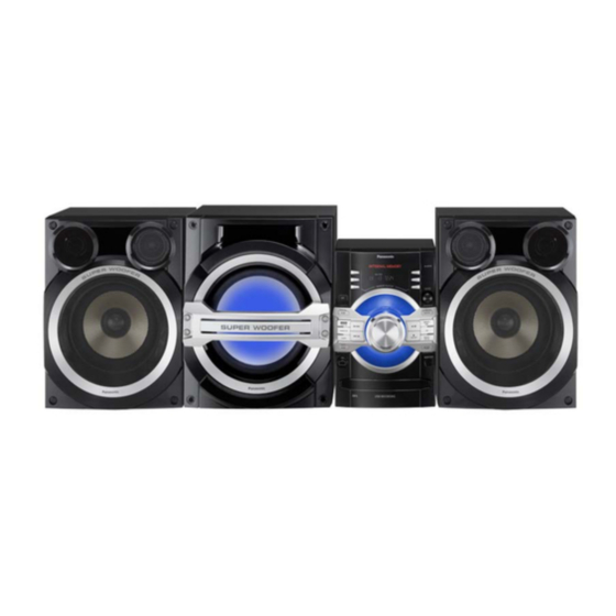
CD Stereo System
PAGE
Advertisement
Table of Contents

Related Manuals for Panasonic SA-AKX76PH


Summary of Contents for Panasonic SA-AKX76PH
-
Page 1: Table Of Contents
8.4. Self-Diagnostic Mode ----------------------------------- 23 prevention --------------------------------------------------10 8.5. Self-Diagnostic Error Code Table -------------------- 23 3 Service Navigation ----------------------------------------------11 8.6. Sales Demonstration Lock Function ---------------- 24 © Panasonic Corporation 2013. All rights reserved. Unauthorized copying and distribution is a violation of law. - Page 2 9 Troubleshooting Guide---------------------------------------- 25 10 Disassembly and Assembly Instructions --------------- 26 10.1. Screw Types----------------------------------------------- 26 10.2. Disassembly Flow Chart-------------------------------- 27 10.3. Main Components and P.C.B. Locations ---------- 28 10.4. Disassembly of Top Cabinet--------------------------- 29 10.5. Disassembly of Front Panel Unit --------------------- 30 10.6.
-
Page 3: Safety Precautions
1 Safety Precautions 1.1. General Guidelines 1. IMPORTANT SAFETY NOTICE There are special components used in this equipment which are important for safety. These parts are marked by in the Schematic Diagrams, Circuit Board Layout, Exploded Views and Replacement Parts List. It is essential that these critical parts should be replaced with manufacturer’s specified parts to prevent X-RADIATION, shock, fire, or other hazards. -
Page 4: Before Use (For Ph Only)
1.2. Before Use (For PH only) Be sure to disconnect the mains cord before adjusting the voltage selector as shown in Figure 1-2 Use a minus(-) screwdriver to set the voltage selector (on the rear panel) to the voltage setting for the area in which the unit will be used. -
Page 5: Safety Parts Information
1.6. Safety Parts Information Safety Parts List: There are special components used in this equipment which are important for safety. These parts are marked by in the Schematic Diagrams, Exploded View & Replacement Parts List. It is essential that these critical parts should be replaced with manufacturer’s specified parts to prevent shock, fire or other hazards. -
Page 6: Warning
2 Warning 2.1. Prevention of Electrostatic Discharge (ESD) to Electrostatically Sensi- tive (ES) Devices Some semiconductor (solid state) devices can be damaged easily by static electricity. Such components commonly are called Elec- trostatically Sensitive (ES) Devices. The following techniques should be used to help reduce the incidence of component damage caused by electrostatic discharge (ESD). -
Page 7: Precaution Of Laser Diode
2.2. Precaution of Laser Diode Caution: This product utilizes a laser diode with the unit turned “on”, invisible laser radiation is emitted from the pickup lens. Wavelength: 790 nm (CD) Maximum output radiation power from pickup: 100 µW/VDE Laser radiation from the pickup unit is safety level, but be sure the followings: 1. -
Page 8: Service Caution Based On Legal Restrictions
2.3. Service caution based on Legal restrictions 2.3.1. General description about Lead Free Solder (PbF) The lead free solder has been used in the mounting process of all electrical components on the printed circuit boards used for this equipment in considering the globally environmental conservation. The normal solder is the alloy of tin (Sn) and lead (Pb). -
Page 9: Handling Precautions For Traverse Unit
2.4. Handling Precautions for Traverse Unit The laser diode in the optical pickup unit may break down due to static electricity of clothes or human body. Special care must be taken avoid caution to electrostatic breakdown when servicing and handling the laser diode in the traverse unit. Cautions to Be Taken in Handling the Optical Pickup Unit 2.4.1. -
Page 10: Grounding For Electrostatic Breakdown Prevention
2.5. Grounding for electrostatic breakdown prevention • As for parts that use optical pick-up (laser diode), the optical pick-up is destroyed by the static electricity of the working environ- ment. Repair in the working environment that is grounded. 2.5.1. Worktable grounding •... -
Page 11: Service Navigation
3 Service Navigation 3.1. Service Information This service manual contains technical information which will allow service personnel’s to understand and service this model. Please place orders using the parts list and not the drawing reference numbers. If the circuit is changed or modified, this information will be followed by supplement service manual to be filed with original service manual. - Page 12 3.1.1. Firmware Update Procedure Start Write encrypted UPD bin to CD-R Turn On main set Insert CD-R (with UPD bin) and close TOC reading "CHECKING" "NO PLAY" process end Writing starts: "0%" -> "20%" -> "40%" -> "60%" -> "80%" -> 100%" "GOOD"...
-
Page 13: Specifications
(200 kHz step) (for PN) analyzer. 75 Ω (unbalanced) Antenna terminals System: SC-AKX76PH-K Amplitude modulation (AM) Main Unit: SA-AKX76PH-K Frequency range 522 kHz to 1629 kHz Speakers System: SB-AKX76PN-K (9 kHz step) (for PH) System: SC-AKX76PN-K 520 kHz to 1630 kHz... -
Page 14: General/Introduction
5 General/Introduction 5.1. Media Information... -
Page 15: Location Of Controls And Components
6 Location of Controls and Components 6.1. Remote Control Key Button Operation... -
Page 16: Main Unit Key Button Operation
6.2. Main Unit Key Button Operation... -
Page 17: Installation Instructions
7 Installation Instructions 7.1. Speaker and A/C Connection... -
Page 18: Service Mode
8 Service Mode 8.1. Cold-Start Here is the procedure to carry out cold-start or initialize to shipping mode. 1. Unplug AC power cord 2. Press & hold [POWER] button 3. Plug AC power cord while [POWER] button being pressed FL Display will show “_ _ _ _ _ _ _ _” 4. -
Page 19: Doctor Mode Table 1
8.2. Doctor Mode Table 8.2.1. Doctor Mode Table 1 Item Key Operation FL Display Mode Name Description Front Key Doctor Mode To enter into Doctor Mode In CD Mode: 1. Press [ ] button on main unit follow by [4] and [7] on remote control. - Page 20 8.2.2. Doctor Mode Table 2 Item Key Operation FL Display Mode Name Description Front Key Volume Setting To check the volume setting of the In Doctor Mode: Check main unit. 1. Press [7], [8], [9] button on the remote control. Press [7]: VOL50 Volume Press [8]: VOL35...
- Page 21 8.2.3. Doctor Mode Table 3 Item Key Operation FL Display Mode Name Description Front Key To display result of In Doctor Mode : Self- Adjustment self-adjustment for CD. 1. Press [10] [4] button Test on the remote control. Display of auto adjustment result Reference table: ERROR Code...
-
Page 22: Reliability Test Mode (Cd Mechanism Unit)
8.3. Reliability Test Mode (CD Mechanism Unit) Below is the process flow chart of the aging test for the CD Mechanism Unit . OPEN First Track Operation Access OPEN wait First Track for 1 s Play 5 s CLOSE Count up Last Track Operation Access... -
Page 23: Self-Diagnostic Mode
8.4. Self-Diagnostic Mode Item Key Operation FL Display Mode Name Description Front Key Self Diagnostic To enter into self diagnostic checking Step 1: Select CD mode Mode (Ensure no disc is inserted). Step 2: Press & hold [ ] button follow by [ ] on main unit for 2 seconds. -
Page 24: Sales Demonstration Lock Function
8.5.2. CD Mechanism Error Code Table (CD Mechanism Unit) Error Code Diagnostic Contents Description of error Automatic FL Display Remarks CD H15 CD Open Abnormal During operation Press [ ] on main unit for POS_SW_R On fail to be next error. detected with 4 sec. -
Page 25: Troubleshooting Guide
9 Troubleshooting Guide "Contents for this section is not available at time of issue"... -
Page 26: Disassembly And Assembly Instructions
10 Disassembly and Assembly Instructions • Illustration is based on SA-AKX76PH-K. Caution Note: • This section describes the disassembly and/or assembly procedures for all major printed circuit boards & main compo- nents for the unit. (You may refer to the section of “Main components and P.C.B Locations” as described in the service manual) •... -
Page 27: Disassembly Flow Chart
10.2. Disassembly Flow Chart 10.4.Top Cabinet 10.5 Front Panel Unit 10.10. Rear Panel 10.19. Fan Unit 10.12. SMPS P.C.B. and 10.6. Panel P.C.B., 10.11. Main P.C.B. Voltage Selector LED P.C.B. and P.C.B. Music Port P.C.B. 10.7. Remote Sensor 10.13. CD Mechanism P.C.B. -
Page 28: Main Components And P.c.b. Locations
10.3. Main Components and P.C.B. Locations... -
Page 29: Disassembly Of Top Cabinet
10.4. Disassembly of Top Cabinet Step 4 Slightly lift up the Top Cabinet in an outward direction as shown. Step 1 Remove 2 screws on each side. Step 5 Remove the Top Cabinet. Step 2 Remove 5 screws. Step 3 Slightly release both side of Top Cabinet outwards as arrow shown. -
Page 30: Disassembly Of Front Panel Unit
10.5. Disassembly of Front Panel Step 5 Release tab at the right side of the Front Panel Unit. Unit • Refer to “Disassembly of Top Cabinet”. Step 1 Detach 30P FFC at the connector (CN2004) on Main P.C.B.. Step 2 Detach 5P Cable at the connector (CN2001) on Main P.C.B.. -
Page 31: Disassembly Of Panel P.c.b., Led P.c.b. And Music Port P.c.b
Step 7 Detach the Front Panel Unit as arrow shown. Step 3 Remove 7 screws. Step 4 Release catches by following the sequences (1-9). 10.6. Disassembly of Panel P.C.B., LED P.C.B. and Music Port P.C.B. • Refer to “Disassembly of Top Cabinet”. •... - Page 32 Step 5 Lift up the Panel P.C.B. and LED P.C.B. from the Front Caution: During assembling, ensure that the Panel P.C.B. is seated properly onto the locators & fully catched. Panel Unit. Caution: During assembling, ensure that the LED P.C.B. is properly insert to the Front Panel Unit.
-
Page 33: Disassembly Of Remote Sensor P.c.b
Caution: During assembling, ensure that the Music Port 10.8. Disassembly of USB P.C.B. P.C.B. is seated properly into the locators & fully catched. • Refer to “Disassembly of Top Cabinet”. • Refer to “Disassembly of Front Panel Unit”. Step 1 Remove 1 screw. Step 2 Release 1 catch. -
Page 34: Disassembly Of Cd Lid
10.9. Disassembly of CD Lid 10.10. Disassembly of Rear Panel • Refer to “Disassembly of Top Cabinet”. • Refer to “Disassembly of Top Cabinet”. • Refer to “Disassembly of Front Panel Unit”. Step 1 Remove 10 screws. Step 1 Remove the spring in order of sequence (1) to (3). Caution: During assembling, ensure that the spring is assembly at correct position. -
Page 35: Disassembly Of Main P.c.b
Step 5 Lift up to remove Inner Chassis Unit from the Rear 10.11. Disassembly of Main P.C.B. Panel. • Refer to “Disassembly of Top Cabinet”. • Refer to “Disassembly of Front panel Unit”. Step 1 Detach 2P Wire at the connector (CN2007) on Main P.C.B.. - Page 36 Step 4 Remove 2 screw. Step 6 Detach 10P FFC at the connector (FP8251) on the Main Step 5 Lift up the Main P.C.B.from the slots at the Inner Chas- P.C.B.. sis Unit according to arrow shown. Step 7 Detach 24P FFC at the connector (FP8201) on the Main P.C.B..
-
Page 37: Disassembly Of Smps P.c.b. And Voltage Selector P.c.b
10.12. Disassembly of SMPS P.C.B. Step 5 Release the P.C.B. Holder.. Step 6 Remove the SMPS P.C.B.. and Voltage Selector P.C.B. Caution: During assembling, ensure that the SMPS P.C.B. is seated properly onto the locators. • Refer to “Disassembly of Top Cabinet.”. •... - Page 38 Step 2 Detach the Voltage Selector P.C.B. from the Rear Panel. Caution: During assembling, ensure that Inner Chassis Unit is catched onto Rear Panel properly. Step 3 Remove 1 screw. Step 6 Remove 2 screws. Step 7 Remove the CD Mechanism Unit. Step 4 Release 2 catches.
-
Page 39: Disassembly Of Cd Interface P.c.b
10.14. Disassembly of CD Interface 10.15. Disassembly of Fan Unit P.C.B. • Refer to “Disassembly of Top Cabinet”. • Refer to “Disassembly of Top Cabinet”. Step 1 Remove 1 screw. • Refer to “Disassembly of Front Panel Unit”. • Refer to “Disassembly of Main P.C.B.”. •... -
Page 40: Service Position
11 Service Position Note: For description of the disassembly procedures, see 11.3. Checking of Main P.C.B. (Side the Section 10. 11.1. Checking of Panel P.C.B. Step 1 Remove Top Cabinet. Step 1 Remove Top Cabinet. Step 2 Remove Front Panel Unit. Step 2 Remove Front Panel Unit. -
Page 41: Checking Of Smps P.c.b
Step 7 Attach 10P FFC at the connector (FP8251) on the Main 11.4. Checking of SMPS P.C.B. P.C.B.. Step 1 Remove Top Cabinet. Step 8 Attch 24P FFC at the connector (FP8201) on the Main Step 2 Remove Front Panel Unit. P.C.B.. -
Page 43: Block Diagram
OPEN SW OPEN SW OPEN SW CD OPEN SW CN7001 CN7002 FP8251 CLOSE SW CLOSE SW CLOSE SW CD CLOSE SW CD INTERFACE P.C.B. NOTE: “ * ” REF IS FOR INDICATION ONLY SA-AKX76PH/PN SERVO & SYSTEM CONTROL (1/2) BLOCK DIAGRAM... - Page 44 STOP/TUNE MODE PLAY/PAUSE KEY3 CN2004 CN6001 KEY3 KEY3 94 REMOTE SENSOR P.C.B. IR6500 REMOTE CONTROL SENSOR CN2004 CN6001 CN6002 CN6500 +3.3V RMT 86 NOTE: “ * ” REF IS FOR INDICATION ONLY SA-AKX76PH/PN SERVO & SYSTEM CONTROL (2/2) BLOCK DIAGRAM...
-
Page 45: Audio
DAP VALID MPORT R ZJ6300* ZJ6000* CN6001 CN2004 MPORT R MUSIC PORT ZJ6300* ZJ6000* CN6001 CN2004 MPORT L MPORT L IC2002 C0JBAR000367 AUDIO PANEL P.C.B. SELECTOR NOTE: “ * ” REF IS FOR INDICATION ONLY SA-AKX76PH/PN AUDIO (1/2) BLOCK DIAGRAM... - Page 46 INPUT A BST A OUT A JK2501 TO AUDIO OUT A BLOCK (1/2) SUBWOOFER JK2501 INPUT B OUT B BST B /RST BST C OUT C /CLIP OUT D /OTW OUT D /FAULT BST D SA-AKX76PH/PN AUDIO (2/2) BLOCK DIAGRAM...
-
Page 47: Power Supply
SWITCH +36V SENSE CN5802 CN2008 +36V SENSE PW +36V 5,6,7 5,6,7 FEEDBACK CIRCUIT IC5801 C0DAZYY00039 SHUNT REGULATOR PC5720 TO POWER SUPPLY BLOCK (2/2) PRIMARY SECONDARY NOTE: “ * ” REF IS FOR INDICATION ONLY SA-AKX76PH/PN POWER SUPPLY (1/2) BLOCK DIAGRAM... - Page 48 CN2001 ZJ6400* VBUS VBUS VBUS VBUS 4 IN OUT 5 VBUS 3 FLG FROM/TO SERVO & SYSTEM CONTROL 1 CTL TO POWER SUPPLY BLOCK (1/2) NOTE: “ * ” REF IS FOR INDICATION ONLY SA-AKX76PH/PN POWER SUPPLY (2/2) BLOCK DIAGRAM...
-
Page 49: Wiring Connection Diagram
3 2 1 S5701 CN5802 CN5802 VOLTAGE ADJ SENSOR TO LOADING P.C.B. (CD MECHANISM UNIT BRS11C) REMOTE SENSOR P.C.B. VOLTAGE SELECTOR P.C.B. (SOLDER SIDE) (SOLDER SIDE) (FOR PH ONLY) NOTE: " * " REF IS FOR INDICATION ONLY. SA-AKX76PH/PN WIRING CONNECTION DIAGRAM... -
Page 51: Schematic Diagram
14 Schematic Diagram • Voltage and signal line : +B signal line : -B signal line 14.1. Schematic Diagram Notes : CD Audio input signal line : Tuner/Music Port/AUX Audio input signal line • This schematic diagram may be modified at any time : Audio output signal line with the development of new technology. -
Page 53: Main (Cd Servo/Micon/Damp) Circuit
DAT3_SD VCCQ DAT3 R8504 10 9 LB8052 R8507 J0JHC0000045 124125 127128 132 133 137 138 142143 146147 152 153 LB8501 C8054 C8042 J0JHC0000045 PW_3R3V_DIG C8504 C8507 C8506 C8501 DGND TO MAIN (CD SERVO) CIRCUIT (3/4) SA-AKX76PH/PN MAIN (CD SERVO) CIRCUIT... - Page 54 (CD MECHANISM UNIT BRS11C) VREF C8203 0.01 VCC(5V) R8215 CD-LD MD/LPD Q8201 B1ADCF000001 DVD-LD LASER DRIVE GND-LD R8212 C8259 C8202 PW_3R3V_CD D8250 C8260 DZ2J056M0L 0.01 C8201 PD_GND LB8202 D8251 DA2J10100L G1C100KA0101 PW_+5R4V TO MAIN (CD SERVO) CIRCUIT (4/4) SA-AKX76PH/PN MAIN (CD SERVO) CIRCUIT...
- Page 55 LB8201 CD_STAT J0JHC0000045 PW_3R3V_DIG CD_MLD R8210 R8211 R8010 2.7K 100K C8013 C8018 R8011 R8002 6.3V100 0.33 100K NRST CD_RESET C8068 3300P R8005 R8006 X8101 MI: MAIN (MICON): SCHEMATIC DIAGRAM - 5 ~ 10 C8015 C8016 SA-AKX76PH/PN MAIN (CD SERVO) CIRCUIT...
- Page 56 R8258 R8261 R8260 R8259 4.7K R8264 1.2K PW_3R3V_CD R8263 C8256 C8261 1000P K8208 C8262 C8252 C8251 CHASSIS GND 10V100 0.01 LB8252 J0JHC0000045 PW_+5R4V LB8251 J0JHC0000045 PW_+5R4V MI: MAIN (MICON): SCHEMATIC DIAGRAM - 5 ~ 10 SA-AKX76PH/PN MAIN (CD SERVO) CIRCUIT...
- Page 57 3.3K R3033 R2070 4.7K QR2001 R2071 3.9K B1GBCFJJ0051 SWITCH R2114 6.8K X2002 TO MAIN (MICON) CD: MAIN (CD SERVO): SCHEMATIC DIAGRAM - 1 ~ 4 CIRCUIT (4/6) DA: MAIN (DAMP): SCHEMATIC DIAGRAM - 11 ~ 14 SA-AKX76PH/PN MAIN (MICON) CIRCUIT...
- Page 58 VP_DET B-IN A+IN PW_+12V +12V RED_LED RED_LED B+IN GREEN_LED R2157 C2081 R2154 GREEN_LED BLUE_LED BLUE_LED SUBW_LED R3106 SUBW_LED R2141 3.3K FAN_OUT R2139 3.3K DC_DET_AMP PW_+15V MGND TO MAIN (MICON) CIRCUIT (3/6) TO MAIN (MICON) CIRCUIT (5/6) SA-AKX76PH/PN MAIN (MICON) CIRCUIT...
- Page 59 USB HIGH SIDE SWITCH R3111 100K QR3000 B1GBCFGN0016 QR102 LED DRIVE B1ADCE000012 SWITCH USB_REC_LED2 C2030 DGND LED_DRV_RST TO MAIN (MICON) CIRCUIT (2/6) CD: MAIN (CD SERVO): SCHEMATIC DIAGRAM - 1 ~ 4 TO MAIN (MICON) CIRCUIT (6/6) SA-AKX76PH/PN MAIN (MICON) CIRCUIT...
- Page 60 6.3V220 0.47 L2005 L2006 L2000 G1C1R0MA0204 G2A380Y00002 PW_CD_3R3V R2011 JK2002 C2010 AM ANT AM ANT AM ANT R2012 R2015 4.7K 4.7K TU_SDA R2018 TU_SCL R2019 R2020 TU_RST DA: MAIN (DAMP): SCHEMATIC DIAGRAM - 11 ~ 14 SA-AKX76PH/PN MAIN (MICON) CIRCUIT...
- Page 61 SDIN3 LRCLKD DAP_I2S_LRCKO SCLKD DAP_I2S_BCKO SDIN4 DAP_I2S_OUT VR_DIG SDOUT C3218 DGND C2075 C2078 LB3201 J0JBC0000134 PW_CD_3R3V R3224 CD: MAIN (CD SERVO): SCHEMATIC DIAGRAM - 1 ~ 4 DA: MAIN (DAMP): SCHEMATIC DIAGRAM - 11 ~ 14 SA-AKX76PH/PN MAIN (MICON) CIRCUIT...
- Page 62 +3.3V VOLTAGE REGULATOR C2089 DZ2000 B0JCPG000030 R2169 COMP C2103 0.01 GND VOUT VSENSE SS/TR R3355 PW_CD_3R3V 1.8M R2170 R2178 PWGND RT/CLK R3354 Q2023 C3307 C2080 C2084 C2086 C2087 C2092 R2188 4700P B1GBCFJJ0041 6.3V1000 10V220 270K SWITCH DGND SA-AKX76PH/PN MAIN (MICON) CIRCUIT...
- Page 63 TO MAIN (DAMP) SP_SW2- CIRCUIT (2/4) SP_FR+LO R2595 R2655 100K C2656 C2684 1000P 0.01 C2657 0.01 C2685 1000P R2656 R2596 100K C2693 1000P SP_FR-LO MI: MAIN (MICON): SCHEMATIC DIAGRAM - 5 ~ 10 TO MAIN (DAMP) CIRCUIT (3/4) SA-AKX76PH/PN MAIN (DAMP) CIRCUIT...
- Page 64 FL-_LO INPUT_D PVDD_CD 0.22 R3631 SP_FL+LO DAMP_FAULT /FAULT PVDD_CD DAMP_OTW /OTW OUT_D DAMP_CLIP /CLIP OUT_D C2552 0.033 R3667 BST_C C2549 0.033 GVDD_CD BST_D C2714 R3652 R3651 MI: MAIN (MICON): SCHEMATIC DIAGRAM - 5 ~ 10 ZJGND_HS3 SA-AKX76PH/PN MAIN (DAMP) CIRCUIT...
- Page 65 100K SP_FL-LO C2694 1000P SP_FL+HI C2695 1000P DGND R2589 R2661 100K C2650 C2686 1000P 0.01 C2651 0.01 R2590 R2662 100K SP_FL-HI R3653 R3654 ZJGND_HS4 C2679 R3501 DGND MI: MAIN (MICON): SCHEMATIC DIAGRAM - 5 ~ 10 SA-AKX76PH/PN MAIN (DAMP) CIRCUIT...
- Page 66 DAMP_CLIP /CLIP OUT_D TO MAIN (DAMP) CIRCUIT (3/4) R3660 C2547 0.033 BST_C PW_+12V C2548 0.033 GVDD_CD BST_D C2524 DGND R3658 R3657 R3656 R3655 ZJGND_HS5 ZJGND_HS1 PW_+36V DAP_VALID MI: MAIN (MICON): SCHEMATIC DIAGRAM - 5 ~ 10 SA-AKX76PH/PN MAIN (DAMP) CIRCUIT...
-
Page 67: Panel Circuit
C6101 C6102 C6201 C6202 POWER SAVE CONTROL IN SCHEMATIC 100P 100P 100P 100P D6010 B0EAMM000057 DIAGRAM - 17 R6025 C6021 5.6K 25V220 R6109 R6110 R6208 R6209 PW_+15V R6032 D6012 B0BC2R4A0006 C6024 FL_GND 16V100 D6008 B0JAME000114 R6028 R6030 SA-AKX76PH/PN PANEL CIRCUIT... - Page 68 1.2K 1.5K 2.2K 3.3K 4.7K 6.8K S6107 S6200 S6207 S6204 S6203 S6202 S6206 S6201 S6208 LATIN/ MEMORY POWER MANUAL EQ REWIND FORWARD D.BASS OPEN/CLOSE PRESET EQ REC/PAUSE REC/PAUSE NOTE: “ * ” REF IS FOR INDICATION ONLY SA-AKX76PH/PN PANEL CIRCUIT...
-
Page 69: Usb, Music Port, Memory Led & Remote Sensor Circuit
1000P DIAGRAM - 16 C6500 C6502 100P CN6500 16V33 DGND PANEL CIRCUIT SYS3.3V (CN6002) IN SCHEMATIC DIAGRAM - 15 NOTE: “ * ” REF IS FOR INDICATION ONLY SA-AKX76PH/PN USB / MUSIC PORT / MEMORY LED / REMOTE SENSOR CIRCUIT... -
Page 70: Smps Circuit
CURRENT R5728 C5720 100P 100K LIMITING SWITCH D5724 DA2J10100L D5722 DZ2J200M0L C5728 1000P C5721 D5723 220P C5722 DA2J10100L 1000P PC5701 FEEDBACK D5727 DA2J10100L R5810 QR5810 B1GBCFLL0037 PCONT SWITCH SA-AKX76PH/PN SMPS CIRCUIT NOTE: “ * ” REF IS FOR INDICATION ONLY... - Page 71 SWITCHING MODE POWER SUPPLY CONTROL TO SMPS R5895 R5893 CIRCUIT (1/2) C5898 R5892 R5786 C5794 R5795 200K D5793 1000P 470K B0HAMP000094 C5790 2200P R5797 R5891 C5899 10V220 C5796 C5795 SA-AKX76PH/PN SMPS CIRCUIT NOTE: “ * ” REF IS FOR INDICATION ONLY...
-
Page 72: Voltage Selector & Cd Interface Circuit
(RED) CLOSE_SW REST_SW MAIN (CD SERVO) DGND CIRCUIT (FP8251) OPEN_SW IN SCHEMATIC LDM- S7201 DIAGRAM - 4 LDM+ RESET TRV- TRV+ M7301* TRAVERSE MOTOR NOTE: “ * ” REF IS FOR INDICATION ONLY SA-AKX76PH/PN VOLTAGE SELECTOR / CD INTERFACE CIRCUIT... -
Page 73: Printed Circuit Board
R2053 R2058 R2222 R3222 R2055 R2060 C2051 R2048 C3000 Q2003 R2109 R2163 R3022 R3007 R2056 R2157 Q2004 C2082 R2161 QR2003 R2158 R2155 R3016 IC2010 R2162 R2156 D2003 R3034 R3017 R3018 QR2002 R2154 C2081 3620A-1 3620A-1 (SIDE A) SA-AKX76PH/PN MAIN P.C.B. - Page 74 LB3401 (TO SUBWOOFER R3108 9-FL+_HIGH VA2002 FP9003 (SB-AKW76)) 1-SW+ 3-FR+_LOW 5-FR+_HIGH 7-FL+_LOW QR3104 1-GND 4-GND (FOR DEBUG) R3114 2-SW- 4-FR-_LOW 6-FR-_HIGH 8FL-_LOW 10-FL-_HIGH 3620A-1 3620A-1 JK2002 TO SPEAKERS AUX IN FM ANT AM ANT (SUBWOOFER/FRONT) (SIDE B) SA-AKX76PH/PN MAIN P.C.B.
-
Page 75: Panel, Usb, Music Port & Memory Led P.c.b
R6101 (CD) (RADIO/EXT-IN) R6111 S6107 C6022 D6006 (CD OPEN/CLOSE) R6100 VR6200 S6104 C6201 R6208 (MEMORY/USB) C6202 R6209 S6103 (ALBUM/TRACK) ALBUM/TRACK NOTE: " * " REF IS FOR INDICATION ONLY SA-AKX76PH/PN PANEL / USB / MUSIC PORT / MEMORY LED P.C.B. -
Page 76: Smps & Voltage Selector P.c.b
C5818 R5805 R5814 IC5899 PC5702 W5916 Q5803 T5751 W5517 W5521 C5832 (SUB TRANSFORMER) D5896 W5519 W5918 R5898 R5893 CN5802 R5909 C5896 R5700 C5895 Q5898 W5908 NOTE: " * " REF IS FOR INDICATION ONLY SA-AKX76PH/PN SMPS / VOLTAGE SELECTOR P.C.B. -
Page 77: Remote Sensor & Cd Interface P.c.b
CD INTERFACE P.C.B. (REP4945A) M7302* (SPINDLE MOTOR) CN6500 C6502 IR6500 S7201 (RESET) SENSOR CN7002 CN7001 M7301* TO LOADING P.C.B. (TRAVERSE (CD MECHANISM MOTOR) UNIT BRS11C) 3556A 3556A NOTE: " * " REF IS FOR INDICATION ONLY SA-AKX76PH/PN REMOTE SENSOR / CD INTERFACE P.C.B. -
Page 79: Appendix Information Of Schematic Diagram
POWER ON STANDBY IC2006 REF NO. MODE CD PLAY STANDBY IC2006 REF NO. MODE CD PLAY STANDBY IC2006 REF NO. MODE CD PLAY STANDBY REF NO. IC2007 MODE POWER ON STANDBY IC2008 REF NO. MODE CD PLAY STANDBY SA-AKX76PH/PN MAIN P.C.B. - Page 80 11.8 29.0 29.0 18.1 18.1 37.4 37.4 37.4 18.0 18.1 37.4 37.4 37.4 18.1 18.1 IC2501 REF NO. MODE CD PLAY 29.0 29.0 STANDBY 29.0 29.0 IC2502 REF NO. MODE CD PLAY 11.7 11.7 STANDBY 11.7 11.7 SA-AKX76PH/PN MAIN P.C.B.
- Page 81 29.0 29.0 IC8001 REF NO. MODE CD PLAY STANDBY REF NO. IC8001 MODE CD PLAY STANDBY IC8001 REF NO. MODE CD PLAY STANDBY IC8001 REF NO. MODE CD PLAY STANDBY IC8001 REF NO. MODE CD PLAY STANDBY SA-AKX76PH/PN MAIN P.C.B.
- Page 82 CD PLAY STANDBY IC8051 REF NO. MODE CD PLAY STANDBY REF NO. IC8251 MODE CD PLAY STANDBY IC8251 REF NO. MODE CD PLAY STANDBY IC8401 REF NO. MODE CD PLAY STANDBY REF NO. IC8501 MODE CD PLAY STANDBY SA-AKX76PH/PN MAIN P.C.B.
- Page 83 12.3 15.4 12.9 30.0 STANDBY 11.6 12.2 12.3 15.4 12.9 30.0 Q2631 Q2632 Q2633 Q2634 Q3301 REF NO. MODE POWER ON 18.1 37.4 18.1 18.1 37.4 18.1 37.4 37.3 STANDBY 18.1 37.4 18.1 18.1 37.4 18.1 37.4 37.3 SA-AKX76PH/PN MAIN P.C.B.
- Page 84 12.0 12.0 QR3000 QR3102 QR3103 QR3104 REF NO. MODE CD PLAY STANDBY SA-AKX76PH/PN MAIN P.C.B. 16.1.7. Panel P.C.B. REF NO. IC6000 MODE CD PLAY -16.1 -14.1 -21.5 -21.5 -19.7 -21.5 -17.8 STANDBY -16.1 -14.1 -21.5 -21.5 -19.7 -21.5 -17.8 IC6000 REF NO.
- Page 85 32.0 REF NO. IC5899 MODE POWER ON 32.0 STANDBY 32.0 Q5701 Q5711 Q5720 Q5721 Q5803 REF NO. MODE POWER ON 28.0 28.0 28.0 32.0 STANDBY 28.0 28.0 28.0 32.0 Q5898 QR5810 REF NO. MODE POWER ON STANDBY SA-AKX76PH/PN SMPS P.C.B.
- Page 86 16.1.9. Waveform Table 3.8Vp-p(50nsec/div) 4Vp-p(50nsec/div) 2Vp-p(10usec/div) 3.8Vp-p(10usec/div) 1.8Vp-p(50usec/div) 3.2Vp-p(1usec/div) 3.2Vp-p(1usec/div) 3.2Vp-p(1usec/div) 36Vp-p(500nsec/div) 36Vp-p(1usec/div) 3.2Vp-p(1usec/div) 36Vp-p(500nsec/div) 36Vp-p(1usec/div) 36Vp-p(500nsec/div) 36Vp-p(1usec/div) 3.2Vp-p(1usec/div)
-
Page 87: Exploded View And Replacement Parts List
(PANEL P.C.B.) CN6002 CN6500 IR6500 CN6001 VR6200 (REMOTE SENSOR P.C.B.) T6000 VR6100 *ZJ6000 *ZJ6400 (USB P.C.B.) (MUSIC PORT P.C.B.) *ZJ6300 CN6400 *ZJ6301 JK6301 SA-AKX76PH/PN-K NOTE: " * " PART IS NOT SUPPLIED / REF IS FOR INDICATION ONLY. CABINET DRAWINGS... - Page 88 ZJ2000 T5751 S5701 *TL5711 (VOLTAGE CN5802 SELECTOR P.C.B.) *TL6 *TL5712 *TL5 (SMPS P.C.B.) (BRS11C) (FOR PH ONLY) CN7002 (CD INTERFACE P.C.B.) CN7001 S7201 SA-AKX76PH/PN-K NOTE: " * " PART IS NOT SUPPLIED / REF IS FOR INDICATION ONLY. CABINET DRAWINGS...
- Page 89 17.1.2. Packaging ACCESSORIES BAG REMOTE CONTROL A1-1 R/C BATTERY COVER AC CORD SA-AKX76PH/PN (FOR PH ONLY) AC CORD (FOR PN ONLY) OI BOOK SB-AKX76PN FM INDOOR ANTENNA AM LOOP ANTENNA AC PLUG ADAPTOR (FOR PH ONLY) POLYFOAM (TOP) SC-AKX76PH/PN-K POLYFOAM (BOTTOM)
- Page 91 17.1.3. Mechanical Replacement Part List Safety Ref. Part No. Part Name & Qty Remarks Description Safety Ref. Part No. Part Name & Qty Remarks RHD26046-L SCREW Description RHD30007-K2J SCREW RHD30111-31 SCREW CABINET RHD30119-S SCREW CHASSIS RHD30119-S SCREW RHDX031008 SCREW L6FALEFH0030 FAN UNIT RMNV0079-1 FL HOLDER...
- Page 92 Safety Ref. Part No. Part Name & Qty Remarks Description RGQ0744-W VOLUME LIGHT SHEET RKW1025-Q FL WINDOW RGU2848-K POWER BUTTON REXX1123-K WIRE (VOLTAGE SELEC- TOR-SMPS) REXX1122-K BLACK WIRE (VOLTAGE SELEC- TOR-SMPS) RHDX30005-J SCREW REXX1159-1 WIRE (MUSIC PORT INNER CHASSIS) RGC0050-W1 VOLUME LIGHT REFLECTOR...
-
Page 93: Electrical Replacement Part List
17.2. Electrical Replacement Part List Safety Ref. Part No. Part Name & Qty Remarks Description IC2006 RFKWMAKX56LM (E.S.D) Safety Ref. Part No. Part Name & Qty Remarks JIGS Description & ADJ IC2007 C3EBEY000037 (E.S.D) PRINTED CIRCUIT IC2008 C1AB00004003 (E.S.D) BOARDS IC2009 C0DBGYY03056 (E.S.D) - Page 94 Safety Ref. Part No. Part Name & Qty Remarks Safety Ref. Part No. Part Name & Qty Remarks Description Description Q2024 B1GBCFJJ0041 TRANSISTOR (E.S.D) D6102 B3AAA0001129 DIODE (E.S.D) Q2631 B1ABCF000231 TRANSISTOR (E.S.D) D6103 B3ABA0000905 DIODE (E.S.D) Q2632 B1ABCF000231 TRANSISTOR (E.S.D) D6104 B3ABA0000905 DIODE...
- Page 95 Safety Ref. Part No. Part Name & Qty Remarks Safety Ref. Part No. Part Name & Qty Remarks Description Description L2000 G2A380Y00002 ANTENNA COIL REMOTE SENSOR L2002 G1CR18JA0020 INDUCTOR L2006 G1C1R0MA0204 INDUCTOR IR6500 B3RAB0000110 REMOTE SENSOR L2007 G1C330MA0291 INDUCTOR L2500 G0C100M00009 INDUCTOR LCD DISPLAY...
- Page 96 Safety Ref. Part No. Part Name & Qty Remarks Safety Ref. Part No. Part Name & Qty Remarks Description Description W1035 D0GDR00JA017 1/8W R2036 D0GBR00JA008 1/10W W1039 D0GDR00JA017 1/8W R2037 D0GBR00JA008 1/10W W1040 D0GBR00JA008 1/10W R2046 D0GB103JA008 1/10W W1041 D0GFR00JA017 1/4W R2047 D0GB102JA008...
- Page 97 Safety Ref. Part No. Part Name & Qty Remarks Safety Ref. Part No. Part Name & Qty Remarks Description Description R2157 D0GB123JA008 1/10W R2662 D0GB104JA008 100K 1/10W R2158 D0GB2R2JA007 1/10W R2667 D0GB822JA008 8.2K 1/10W R2159 D0GB2R2JA007 1/10W R2668 D0GB104JA008 100K 1/10W R2160 D0GB2R2JA007...
- Page 98 Safety Ref. Part No. Part Name & Qty Remarks Safety Ref. Part No. Part Name & Qty Remarks Description Description R3314 D0GB184JA008 180K 1/10W R5865 D1BD1800A066 1.8K 1/8W R3351 D0GBR00JA008 1/10W R5890 D0GB222JA065 2.2K 1/10W R3354 D0GB102JA008 1/10W R5891 D1BB3302A074 1/10W R3355 ERJ3GEYJ185V...
- Page 99 Safety Ref. Part No. Part Name & Qty Remarks Safety Ref. Part No. Part Name & Qty Remarks Description Description R8001 ERJ2GE0R00X 1/16W C2020 F1H1H561B052 560pF R8002 D0GB103JA065 1/10W C2021 F1H1E105A153 R8005 D0GB105JA065 1/10W C2024 F1H1E105A153 R8006 D0GB221JA065 1/10W C2025 F1H1E105A153 R8010 D0GA104JA023...
- Page 100 Safety Ref. Part No. Part Name & Qty Remarks Safety Ref. Part No. Part Name & Qty Remarks Description Description C2529 F1H1H104B047 0.1uF C2747 F1K1H105A138 C2530 F1H1H104B047 0.1uF C2750 ECQV1H474JL3 0.47uF C2541 F1H1H333B055 0.033uF 50V C2751 ECQV1H474JL3 0.47uF C2542 F1H1H333B055 0.033uF 50V C2752 ECQV1H474JL3...
- Page 101 Safety Ref. Part No. Part Name & Qty Remarks Safety Ref. Part No. Part Name & Qty Remarks Description Description C5895 F1H1H104B047 0.1uF C8042 F1H1C104A008 0.1uF C5896 F1H1H104B047 0.1uF C8043 F1H1C104A008 0.1uF C5897 F1H1H103B047 0.01uF C8044 F1H0J4750005 4.7uF 6.3V C5898 F1H1H104B047 0.1uF C8045...
- Page 102 MMH1303...