Table of Contents
Advertisement
Report No. 189122-1050009
WARNING: IF THE INFORMATION IN
THIS MANUAL IS NOT FOLLOWED EX-
ACTLY, A FIRE OR EXPLOSION MAY
RESULT CAUSING PROPERTY DAMAGE,
PERSONAL INJURY OR LOSS OF LIFE.
FOR YOUR SAFETY: Do not store or use gaso-
line or other flammable vapors or liquids in the
vicinity of this or any other appliance.
FOR YOUR SAFETY: What to do if you smell gas:
• DO NOT light any appliance.
• DO NOT touch any electrical switches.
• Do not use any phone in your building.
• Immediately call your gas supplier from
a neighbor's phone. Follow your gas
suppliers instructions.
• If your gas supplier cannot be reached, call
the fire department.
Installation and service must be performed
by a qualified installer, service agency or
the gas supplier.
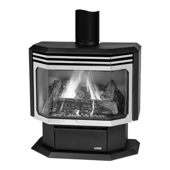
INSTALLATION AND OPERATION
FREESTANDING VENTED GAS FIRED ROOM HEATERS
Shown with optional gold door and brickaded interior
Model: L30 DVF-2 (Direct-Vent)
RETAIN THIS MANUAL FOR FUTURE REFERENCE
P/N 775,029M Rev. B, 8/04
This appliance may be installed in an aftermarket permanently located,
manufactured (mobile) home, where not prohibited by local codes
AVERTISSEMENT:
SUIVRE LES INSTRUCTIONS DONNÉ DANS CETTE
NOTICE POUR RÉDUIRE AU MINIMUM LE RISQUE
D'INCENDIE OU POUR ÉVITER TOUT DOMMAGE
MATÉRIEL, TOUTE BLESSURE OU LA MORT.
POUR VOTRE SÉCURITÉ: Ne pas entreposer ni
utiliser d'essence ni d'autre vapeurs ou liquides
inflammables dans le voisinage de cet appareil ou
de tout autre appareil.
POUR VOTRE SÉCURITÉ: Que faire si vous sentez
une odeur de gaz:
• Ne pas tenter d'allumer d'appareil.
• Ne touchez à aucun interrupteur. Ne pas vous
servir des téléphones se trouvant dans le batiment
où vous vous trouvez.
• Evacuez la piéce, le bâtiment ou la zone.
• Appelez immédiatement votre fournisseur de gaz
depuis un voisin. Suivez les instructions du
fournisseur.
• Si vous ne pouvez rejoindre le fournisseur de gaz,
appelez le service dos incendies.
L'installation et service doit être exécuté par un qualifié
installeur, agence de service ou le fournisseur de gaz.
MANUAL
ASSUREZ-VOUS
DE
BIEN
Advertisement
Table of Contents

Related Manuals for Lennox Hearth Products L30 DVF-2


Summary of Contents for Lennox Hearth Products L30 DVF-2
-
Page 1: Installation And Operation
MANUAL FREESTANDING VENTED GAS FIRED ROOM HEATERS Shown with optional gold door and brickaded interior Model: L30 DVF-2 (Direct-Vent) RETAIN THIS MANUAL FOR FUTURE REFERENCE P/N 775,029M Rev. B, 8/04 This appliance may be installed in an aftermarket permanently located,... -
Page 2: Important Warnings
IMPORTANT WARNINGS / CAUTIONS CAUTION: READ THIS MANUAL THOROUGHLY BEFORE STARTING INSTALLATION. FOR YOUR SAFETY, FOL- LOW THE INSTALLATION, OPERATION AND MAINTENANCE INSTRUCTIONS EXACTLY WITHOUT DEVIATION. FAILURE TO FOLLOW THESE INSTRUCTIONS MAY RESULT IN A POSSIBLE FIRE HAZARD AND MAY VOID THE WARRANTY. -
Page 3: Table Of Contents
It is our goal at Lennox Hearth Products to provide you, our valued customer, with an appliance that will ensure you years of trouble free warmth and pleasure. -
Page 4: Planning Your Installation
PLANNING YOUR INSTALLATION LOCAL AND NATIONAL CODE REQUIREMENTS The installation of these appliances must conform with local codes or, in the absence of local codes, with the National Fuel Gas Code, (for USA) NFPA 54 / ANSI Z223.1-latest edition. Air Circulation Blower: The blower electrical power cord must be electrically grounded per local codes or per electrical codes: In USA, NEC, ANSI / NFPA 70-Latest Edition. - Page 5 PLANNING YOUR INSTALLATION QUESTIONS TO ASK THE LOCAL BUILDING OFFICIAL Correct installation is critical and imperative for reducing fire hazards and perilous conditions that can arise when gas appli- ances function improperly. The appliance must be installed per manufacturers’ instructions. Gas appliance equipment and installations must conform to appropriate local codes and applicable state and federal re- quirements.
-
Page 6: Manufactured (Mobile) Home Installation
Floor 0 inches MANUFACTURED (MOBILE) HOME REQUIREMENTS Model L30 DVF-2 may be installed in an aftermarket perma- nently located, manufactured home, where not prohibited by local codes. When installed in Manufactured Housing the follow- ing supplemental requirements must be met: The appliance must be secured to the floor. -
Page 7: Installation
INSTALLATION This appliance is designed to be vented with a 4” x 6 5/8” direct-vent pipe. Each direct-vent appliance must use its own separate vent system VERTICAL TERMINATION VERTICAL TERMINATION WITH NO OFFSETS WITH 2 OFFSETS Min. Vertical Pipe Length: 5 feet Min. - Page 8 INSTALLATION VENT RESTRICTOR RING INSTALLATION Recommended Restrictor Ring Placement For Optimum Stove Performance If total vertical venting is 16 feet or higher, install 1 restrictor ring (included) between the appliance outlet / inlet collar and first section of pipe. Guideline for Installing Flue Restrictor Ring in Co-Axial Direct-Vent Pipe If the total vertical venting is 16 feet or higher, installation of 1 restrictor ring is rec-...
- Page 9 INSTALLATION See Pipe Manufacturers Instructions For Installation Of Venting Components & Clearances. DIRECT VENT SYSTEM COMPONENTS – Model L30 DVF-2 The following Direct-Vent system components may be safely used with this appliance. Model # Brand: SECURITY / Description SV 0 SHK Standard Horizontal Term.
- Page 10 INSTALLATION DIRECT VENT RETROFIT OF EXISTING CHIMNEY SYSTEM - An existing Class-A (wood-burning) Metal Chimney or Masonry Chimney can be converted to a direct vent system. Use one of the following chimney conversion kits listed below. Have the existing chimney system inspected by a professional prior to the conversion.
- Page 11 INSTALLATION The venting terminals should not be recessed into a wall or siding. A = 2” Clearances above grade, veranda, porch, deck or balcony. B = 12” Clearance to window or door that may be opened. C = 9” (USA) Clearance to permanently closed win- dow.12”...
- Page 12 INSTALLATION GAS SUPPLY HOOKUP If using pipe other than black iron pipe see NFPA 54-National Fire Protec- tion Association / ANSI Z223.1-American National Standards Institute; and local code for specific requirements for the type of pipe used. Alter- native gas piping systems such as CSST may be used subject to local code and proper sizing.
- Page 13 INSTALLATION DOOR OPERATION After setup of the logs and embers is complete, the glass door must be closed. The glass door is mounted on hinges at the left side of the firebox and is secured in the closed position by two draw latches mounted on the right side of the firebox.
- Page 14 INSTALLATION GAS APPLIANCE FINAL ASSEMBLY After the appliance has been properly installed and all gas connections have been made and tested, you can now install the log set. See Door Assembly on page 14 for door removal instructions. INSTALLING LOG SET: WARNING: If logs are not installed according to the directions in this manual, flame impingement and improper combustion could occur and result...
- Page 15 INSTALLATION INSTALLATION CHECK LIST Read and understand these instructions before using appliance. Go through this installation checklist: Ensure that the log set is properly installed. Use cau- tion when handling the logs. See page 12. Reinstall the door frame assembly. See Door As- sembly on page 14.
-
Page 16: Care And Operation
CARE AND OPERATION FOR YOUR SAFETY READ BEFORE LIGHTING WARNING: If you do not follow these instructions exactly, a fire or explosion may result causing property damage, personal injury or loss of life. A. This appliance has a pilot which must be lit. When lighting the pilot, follow these instructions exactly. -
Page 17: Care And Operation
(See Small Area Paint Touch-Up, page 19). Paint is avail- able at your local authorized Lennox Hearth Products dealer. Never attempt to paint a hot stove. COMBUSTION CHAMBER RELIEF DOORS... -
Page 18: Propane Conversion
PROPANE CONVERSION PROPANE CONVERSION PROCEDURE (Only required if Propane gas is used) This appliance is designed to operate on natural gas, or propane (LP). It is factory set for use with natural gas and requires field conversion for use with propane. The use of other fuels or com- bination of fuels will degrade the performance of this system and may be dangerous. -
Page 19: Propane Conversion
PROPANE CONVERSION 7. High / Low Pressure Regulator Installation Procedure: a. Remove regulator cap and conversion screw (see fol- lowing illustration). b. Install the new conversion screw (Red = Propane LP gas, Blue = Natural Gas). Ensure that the conversion screw is finger tight. -
Page 20: Maintenance
MAINTENANCE Always Turn Off Gas Control Valve Before Cleaning. Annual Maintenance Should Only Be Performed By A Qualified Service Technician: LOG SET Removing & Cleaning Logs - Carefully remove the logs (remov- ing top logs, then lifting front log out, then rear log). Use care when handling the fiber logs, as they become quite fragile after curing. -
Page 21: Maintenance
MAINTENANCE Always Turn Off Gas Control Valve Before Cleaning. Annual Maintenance Should Only Be Performed By A Qualified Service Technician: PERIODIC CHECK OF PILOT AND BURNER FLAMES Check the operation of the pilot and cycle the burner. Visually check the flame of the burner making sure the flames are steady;... -
Page 22: Wiring Diagrams
WIRING DIAGRAMS GAS CONTROL AND SAFETY SYSTEM WIRING DIAGRAM CAUTION: Label all wiring prior to disconnection when servicing controls. Wiring errors can cause improper and dangerous opera- tion. Verify proper operation after servicing. The gas control wiring diagram shown here should be used by service technicians for guidance when troubleshooting problems with the pilot safety (millivolt) system or burner remote control system or when locating system components for repair / replacement. -
Page 23: Troubleshooting
TROUBLESHOOTING Qualified Technicians Only PROBLEM 1) Pilot will not light, and Piezo Igniter does not produce a heavy blue spark. 2) Pilot will not light, but Piezo Igniter pro- duces a heavy blue spark. 3) Pilot will not stay lit. 4) Pilot flame stays lit, but main burner will not light. -
Page 24: Replacement Parts
REPLACEMENT PARTS Model: L30 DVF-2 Item # Description Trim, Decorative Window Frame, Charcoal Burner Assembly Blower, Air Circulating Thermal Fan Switch Power Cord (blower) Rheostat w / Knob (speed control for blower) Item # Description Cat. No. On / Off Switch, Pkg. of 3... -
Page 25: Optional Accessories
OPTIONAL ACCESSORIES Item # Description Door Kit, L30 DVF-2, Gold Brickaded Interior Kit, L30 Deluxe Remote Control (Thermostatically controlled) Remote Control (Standard On / Off) Wall Thermostat Kit Touch-up Spray Paint Kit, Charcoal Glowing Embers, 1 oz bag PAGE 25... -
Page 26: Specifications
SPECIFICATIONS: Model L30 DVF-2 Flue Size 4” – Top Vent Intake Pipe 6.625” (6 5/8”) Height Overall 30 5/8” Height 29 1/8” Width 30 1/8” Depth 16 1/8” Fuel Natural Gas (standard) (or) LP Gas (convertible). Gas inlet 3/8” NPT-Male/Flex Line (or) remove flex, 3/8”... -
Page 27: Safety / Listing Label
SAFETY / LISTING LABEL (RATING PLATE) If the rating plate on the unit is different than shown here, the rating plate on the unit is the correct one. PAGE 27... -
Page 28: Ownership Record And Service Log
OWNERSHIP RECORDS Dealer’s Name: Dealer’s Address: City: Serial Number: Notes: SERVICE AND MAINTENANCE LOG Service Service Service Date Technician Description State: Date of Purchase: PAGE 28 Zip Code: Date Installed:... - Page 29 LENNOX reserves the right to make changes at any time, without notice, in design, materials, specifications, prices and also for discontinued colors, styles and products. Consult your local distributor for fireplace code information Printed in U.S.A LENNOX HEARTH PRODUCTS 2001 P/N 775,029M REV. B 08/2004 NOTE: DIAGRAMS & ILLUSTRATIONS NOT TO SCALE.