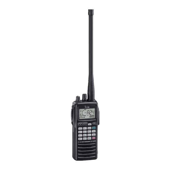
Icom IC-A24E Instruction Manual
Vhf air band transceiver
Hide thumbs
Also See for IC-A24E:
- Instruction manual (40 pages) ,
- Service manual (36 pages) ,
- Instruction manual (40 pages)
Table of Contents
Advertisement
Advertisement
Table of Contents

Related Manuals for Icom IC-A24E


Summary of Contents for Icom IC-A24E
- Page 1 INSTRUCTION MANUAL VHF AIR BAND TRANSCEIVER iA24E iA6E IC-A24E IC-A6E...
-
Page 2: Foreword
Antenna ................1 IC-A24E/A6E VHF AIR BAND TRANSCEIVER is designed w Belt clip ................1 and built with Icom’s state of the art technology and crafts- e Handstrap ............... 1 manship. With proper care this product should provide you with years of trouble-free operation. -
Page 3: Table Of Contents
SUPPLIED ACCESSORIES ............. i I “TAG” channel setting ............17 TABLE OF CONTENTS ..............ii PRECAUTIONS................iii 6 VOR NAVIGATION (IC-A24E only)........18 – 24 I VOR indications ..............18 1 ACCESSORY ATTACHMENT ..........1 I VOR functions ..............19 2 PANEL DESCRIPTION ............ -
Page 4: Precautions
NEVER connect the transceiver to an AC outlet or to a The use of non-Icom battery packs/chargers may impair power source of more than 11.5 V DC. Such a connection will transceiver performance and invalidate the warranty. damage the transceiver. -
Page 5: Accessory Attachment
ACCESSORY ATTACHMENT D Antenna D Belt clip Conveniently attaches to your belt. CAUTION: DO NOT transmit without an antenna. Other- Attach the belt clip with the supplied screws as below. wise the transceiver may be damaged. NOTE: Use the supplied screws only. Insert the supplied antenna into the antenna connector and screw down the antenna as shown below. -
Page 6: Panel Description
PANEL DESCRIPTION I Panel description IC-A24E IC-A6E Microphone Speaker... - Page 7 PANEL DESCRIPTION q BACKLIGHT SWITCH [LIGHT] u SQUELCH KEY [SQL] (p. 8) ➥ Push [SQL], then rotate [DIAL] to select the Turns the backlight for display and keypad ON or OFF. squelch level. w PTT SWITCH [PTT] (p. 9) • 24 squelch levels and squelch open (0) are available. Push and hold to transmit;...
- Page 8 , then push [ANL• ] to start the SCAN ing/connecting the CP-20 from/to the ciga- scan function. IC-A24E/A6E rette lighter socket. !3 EMERGENCY KEY [121.5 MHz] (p. 11) CP-20 (for 11 24 V) Push for 2 sec. to select the 121.5 MHz emergency (optional) frequency.
- Page 9 “TAG” channel. (p. 17) the DVOR display in NAV band. (p. 19)* ➥ Corrects the deviation while using “TO” flag.* ➥ Push These functions available on the IC-A24E only. , then push [3• ] to change the FROM course indicator characteristics to “FROM”...
-
Page 10: I Function Display
RX INDICATOR (p. 9) Appears when receiving a signal or when the squelch opens. r DUPLEX INDICATOR (IC-A24E only) (p. 24) ➥ “DUP” appears when the duplex function is activated in NAV mode. ➥ “DUP” blinks while setting the duplex frequency. -
Page 11: Panel Description
PANEL DESCRIPTION i TAG CHANNEL INDICATOR (p. 17) !4 COURSE INDICATORS (IC-A24E only) (p. 19) ➥ Indicates where your aircraft is located on a VOR radial “ ” appears when the selected memory channel is set as a TAG channel. -
Page 12: Basic Operation
BASIC OPERATION I Setting a frequency I Setting a squelch level ï Using keypad The transceiver has a noise squelch circuit to mute undesired q Push [PWR] for 2 sec. to turn power ON, then push noise while receiving no signal. q Push [SQL], then rotate [DIAL] to select the squelch level. -
Page 13: I Receiving
BASIC OPERATION I Receiving I Transmitting q Push [PWR] for 2 sec. to turn the power ON. CAUTION: Transmitting without an antenna may damage w Push [SQL], then rotate [DIAL] counterclockwise to select the transceiver. the squelch level 0. e Rotate [VOL] to adjust the audio level. r Push [SQL], then rotate [DIAL] clockwise until the noise is NOTE: To prevent interference, listen on the frequency be- muted. -
Page 14: I Low Battery Indicator
BASIC OPERATION I Low battery indicator D Deletes the stored recall channel q Push to select the deleting recall channel. Low battery indicator appears Low battery indicator w Push , then push [CLR• ] for 2 sec. to delete it. when the battery power has de- •... -
Page 15: I Accessing 121.5 Mhz Emergency Frequency
When using an headset (other manufacture’s product), the transceiver outputs your transmitted voice to the headset for The IC-A24E and IC-A6E can set to the121.5 MHz emer- monitoring. Connect the optional headset with the transceiver gency frequency quickly. This function can be activated even... -
Page 16: Memory Operation
MEMORY OPERATION I Memory channel selection I Transferring memory contents The transceiver has 200 memory channels for storage of often-used frequencies along with 6-character notes. This function transfers a memory channel’s contents into the frequency mode. This is useful when searching for signals q Push [MR•... -
Page 17: I Programming A Memory Channel
MEMORY OPERATION I Programming a memory • EXAMPLE: Programming 118.975 MHz into memory BANK 3/ memory channel 9. channel Push The transceiver has 200 (20 CH × 10 BANK) memory chan- nels for storage of often-used frequencies. q Push [CLR• ] to select the frequency mode, if neces- sary. -
Page 18: I Memory Names
MEMORY OPERATION I Memory names ï Programming memory names Character Character Key Character 1, Q, Z 2, A, B, C 3, D, E, F The memory channel can display a 6-character names in- stead of the programmed frequency. 4, G, H, I 5, J, K, L 6, M, N, O 7, P, R, S... -
Page 19: Memory Operation
MEMORY OPERATION • EXAMPLE: Programming 125.000 MHz into memory BANK 1/ memory channel 17 with “AIR-23” as a comment. Push Push Push Push Push Push Push Push Push Push NOTE: Push , then push [0• ], and rotate [DIAL] BANK to select the BANK number, if desired. -
Page 20: Scan Operation
SCAN OPERATION I Scan types I COM band scan q Push [CLR•DEL] to select the frequency mode. The transceiver has 2 scan types to suit your needs. w Push [SQL], then rotate [DIAL] to set the squelch level to COM BAND SCAN the point where noise is just muted. -
Page 21: I "Tag" Channel Setting
SCAN OPERATION I “TAG” channel setting Memory channels can be specified to be skipped for the memory channel scans respectively. The “TAG” channel func- tion is only available during scan operation. Push then Appears the “TAG” indicator. Memory channel 15 is Memory channel 15 is scanned during memory skipped during scan. -
Page 22: Vor Navigation (Ic-A24E Only)
DVOR MODE To-from flag Course indicator indicator Push [F] then [1 Push [F] then [4 DVOR CDI MODE General VOR equipment Function display of the IC-A24E Course indicator To-from flag indicator FROM To-from flag indicator Two-degree deviation Course marks indicator... -
Page 23: I Vor Functions
• When using the ‘TO’ flag and passing through the VOR station, When entering the NAV band, 108.000–117.975 MHz, the the ‘TO’ flag changes to the ‘FROM’ flag automatically. IC-A24E selects the DVOR mode automatically. • When turning power ON, the ‘FROM’ flag is selected automati- cally. -
Page 24: I Flying To A Vor Station
VOR station. • ‘Ω’ or ‘≈’ appears to indicate your aircraft is off course to the right The IC-A24E shows the deviation from a VOR station. or left, respectively. Correct your course until ‘Ω’ or ‘≈’ disap- pears. - Page 25 VOR NAVIGATION (IC-A24E ONLY) 330 340 310 320 123.65 Magnetic THE AIRCRAFT IS ON COURSE VORTAC north SEATTLE 116.8 Ch 115 SEA station 330 340 310 320 123.65 Magnetic THE AIRCRAFT IS OFF COURSE VORTAC north SEATTLE 116.8 Ch 115 SEA...
-
Page 26: I Entering A Desired Course
I Crosschecking position q Select 2 VOR stations on your aeronautical chart. The IC-A24E shows not only the deviation from the VOR sta- w Push the keypad or rotate [DIAL] to set the frequency of tion but the deviation from the desired course. -
Page 27: Crosschecking Position
VOR NAVIGATION (IC-A24E ONLY) EXAMPLE: Entering the desired course bearing 65° to a VOR station. CROSSCHECKING POSITION 123.65 VORTAC VORTAC OLYMPIA SEATTLE 330 340 330 340 310 320 310 320 113.4 Ch 81 OLM 116.8 Ch 115 SEA Magnetic north... -
Page 28: I Duplex Operation
VOR NAVIGATION (IC-A24E ONLY) I Duplex operation D Operating the duplex function q Set the desired frequency in NAV band. • NAV band frequency range: 108.00–117.975 MHz The duplex function allows you to call a flight service station w Push , then push [6•... -
Page 29: Battery Packs
BATTERY PACKS I Battery charging I Battery cautions CAUTION! NEVER Prior to using the transceiver for the first time, the battery insert battery pack/transceiver pack must be fully charged for optimum life and operation. (with the battery pack attached) with wet or soiled into the charger. -
Page 30: I Optional Battery Case
R CAUTION ! batteries together. • DO NOT modify the CP-20. A modifica- IC-A24E/A6E with the • Keep battery contacts clean. It’s a good idea to clean bat- tion could cause a fire or electrocution. attached battery pack tery terminals once a week. -
Page 31: I Optional Battery Chargers
NOTE: Attach the spacer (Spacer B/C) to the adapter (Spacer A) NOTE: Attach the spacer (Spacer B/C) to the adapter (Spacer A) with orientation as illustrated below. with orientation as illustrated below. IC-A24E/A6E Turn power OFF Check orientation Check orientation... -
Page 32: Cloning
CLONING Cloning allows you to quickly and easily transfer the NOTE: DO NOT transfer the data from IC-A24E to programmed data from one transceiver to another IC-A6E, when the data contains the NAV band data. In transceiver, or, data from PC to a transceiver using the such case, cloning error may occur. -
Page 33: Troubleshooting
TROUBLESHOOTING If your transceiver seems to be malfunctioning, please check the following points before sending it to a service center. PROBLEM POSSIBLE CAUSE SOLUTION REF. No power comes on. • The battery is exhausted. • Recharge the battery pack. pgs. 25–27 •... -
Page 34: Specifications
118.000 to 136.975 1.0 W (CW) typical 108.000 to 136.975* • Modulation : Low level modulation *: IC-A24E only, IC-A6E; 118.000 to 136.975 MHz • Modulation depth : 85% • Mode : A3E • Audio harmonic distortion : Less than 10% (at 85% ±3 dB •... -
Page 35: Options
CIGARETTE LIGHTER CABLE ➥ Charges the battery pack through a cigarette lighter socket*. • BC-110AR/DR WALL CHARGER ➥ Operates IC-A24E/A6E through a cigarette lighter socket*. The same as supplied with the transceiver. •BC-119N + AD-101 *Both 12 V and 24 V batteries are available. -
Page 36: Optional Headset Connection
3.5 mm ( 1 / 8 ") diameter plug, if required. OPC-499 HEADSET (Must be purchased separately) NOTICE! Some headsets do not work properly when used with the IC-A24E/A6E. Therefore, ask your dealer for details about headsets IC-A24E/A6E compatible for operation with the IC-A24E/A6E with the headset. -
Page 37: About Doc
EN301 489-22 (2003-11) iv) UNE EN 60215 + A2 Signature CE Versions of the IC-A24E/A6E which display This warning symbol indicates that this equipment the “CE” symbol on the serial number seal, operates in non-harmonised frequency bands comply with the essential requirements of the... - Page 38 MEMO...
- Page 39 MEMO...
- Page 40 < Intended Country of Use > A-6404D-1EU-w Printed in Japan 1-1-32 Kamiminami, Hirano-ku, Osaka 547-0003, Japan © 2005–2006 Icom Inc.