Leica 2 User Manual
Gps equipment
Hide thumbs
Also See for 2:
- Instructions manual (192 pages) ,
- Field manual (45 pages) ,
- Brochure & specs (8 pages)
Advertisement
Quick Links
Advertisement

Related Manuals for Leica 2


Summary of Contents for Leica 2
- Page 2 Congratulations on your purchase of a new System GPS500 from Leica Geosystems. This manual contains important safety directions (refer to section "Safety Instructions") as well as instructions for setting up the product and operating it. Read carefully through the User Manual before you switch on the instrument.
- Page 3 Introduction System description Getting started with new equipment Care and Transport Safety Instructions Technical Specifications...
- Page 4 Introduction ... 5 System description ... 6 GPS Receiver ... 6 Post-processing software ... 6 Getting started with new equipment ... 7 SKI-Pro (SKI-Pro-L1) post-processing software ... 7 Receiver Hardware ... 7 Charge the batteries ... 8 Set Up the Equipment ... 9 Measuring with the default configuration parameters ...
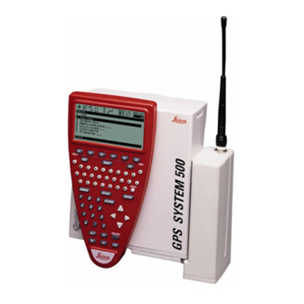
- Page 5 Leica Geosystems GPS System 500 comprises of GPS receiver hardware and PC based software for GPS Surveying and related applications. The Main components are: • GPS Receiver: Receive the satellite signals. • GPS Terminal: Keyboard and Display device to steer the Receiver •...
- Page 6 The GPS Receiver receives the GPS signal from the NAVSTAR satellites and calculates a range to all visible satellites. There are various types of Receivers available: SR510 - 12 L1 channels, code and phase SR520 - 12 L1, 12 L2 channels,...
-
Page 7: Introduction
Should this not be the case, install the software as follows: 1. Insert the CD-ROM into the CD drive of your PC. 2. Select Install SKI-Pro from the menu. 3. Follow the instructions given by the installation shield. The software contains a comprehen- sive Online Help System. - Page 8 Charge the batteries with the Leica Geosystems battery charger pro- vided. GEB121, GEB70 or GEB71 batteries may be used to power the GPS equipment. The GEB121 batteries may be charged using GKL111 or GKL122 chargers. Charger GKL122 GEB70 or GEB71...
- Page 9 Successful GPS surveys require undisturbed satellite signal reception. This means that GPS Receivers should be set up in locations which are free of obstructions. No obstacles like trees, buildings, mountains, etc. should block the line between the GPS antenna and GPS satellites. This holds true in particular for the Receiver which serves as the reference.
- Page 10 Turn on the sensor by pressing the ON-button on the terminal. One of the following two screens will appear on the display: Step 2: Study the Icons Most important at this stage is the top part of the screen which contains several symbols (icons) which indicate the current system status.
- Page 11 Upon power on you will first recog- nize the Number of visible Satel- lites icon, indicating the number of satellites which are theoretically visible at the current location and time. Usually this number varies between 4 and 9, depending on the satellite geometry.
- Page 12 F1 CONT. (If only lines 1 to 3 are visible at this stage press F4 SHOW first). Then press 2 to get access to the Format Memory Module panel, or alternatively use the cursor key to navigate to 2 Format Memory Module and press ENTER;...
- Page 13 You are now in the Utilities \ Format Memory Module panel: If you want to format the PC-card just press F1 CONT to format the card. If you want to format the internal memory press ENTER. A list-box opens which allows you to select the internal memory.
- Page 14 Step 4: Begin a Survey Enter the Survey operation by either pressing 1 in the Main\ panel or by first navigating to 1 Survey via cursor keys and then pressing ENTER or F1 CONT. The following panel will appear: Some basic decisions have to be made in this panel: Which configuration set should be activated, which job the raw data...
- Page 15 Now use the cursor up or cursor down key on the terminal to highlight the PP_STAT line. Then press ENTER or F1 CONT. Jobs are used to organise and structure the data you collect in the field. Jobs can comprise an unlimited number of points together with all related information (raw measure- ments, codes, point annotation, etc.).
- Page 16 You can now enter a name for a new job; press ENTER upon completing the input of the name. Input fields for description and creator are optional and can be left blank. As an example we can create a new job called Test : By default the new job will be as- signed to the PC-card .
- Page 17 Now press F1 CONT to confirm the selection of the newly created job. Finally you have to select the an- tenna type and and antenna setup which you are using. Normally this will be AT502 on tripod (or AT501 on tripod in case of a SR510 sensor).
- Page 18 It is time to check again the icons on the top of the display: The Position Mode icon should be available, the Position Mode icon still indicates "moving" , the Number of visible satellites icon should display a number greater or at least 4, and the number of used satellites should be identical to the number of visible satellites.
- Page 19 Now use the height hook to deter- mine the height of the antenna above the survey marker. Insert the height hook into the carrier and measure the height between the white mark at the bottom of the height hook and the survey marker.
- Page 20 Datalogging should continue depend- ing on your observation plan: a receiver used as reference has to run permanently until all rover site occu- pations are completed. If a unit is operated as a roving receiver the site occupation time depends mainly on the baseline length and your accu- racy requirements.
- Page 21 Card memory card is getting warm. In most cases, a short introductory course to the software will have been given by the local Leica Geosystems representative. To import and process the data proceed as follows: • Switch on the computer, start Windows, start SKI-Pro.
- Page 22 • Process the data Select the Data-Processing view of the project you want to process. The data which was previously reported appears on the screen in both a text and also graphical format. You must tell the program which station is the Reference and which points are Rover.
- Page 23 When dispatching the instrument, always use the complete original Leica Geosystems packaging (case and cardboard box). Never carry the instrument loose in a road vehicle. It can be affected by shock and vibration. Always carry it in its case and secure it.
- Page 24 The person responsible for the equipment must ensure that all users understand these directions and adhere to them. Leica Geosystems GPS equipment is designed and intended for the following applications: - Measuring and computing coordinates using P-code and/or...
- Page 25 External Antenna: Use in rain is permissible. After long term use in this environment the External Antenna must be checked by a Leica Geosystems service technician. - Area of responsibility of the manufacturer of the original equipment Leica Geosystems...
-
Page 26: Safety Instructions
- To understand the safety instructions on the product and the instructions in the user manual. - To be familiar with local regulations relating to accident prevention. - To inform Leica Geosystems immediately if the equipment becomes unsafe. WARNING The absence of instruction, or... - Page 27 - Touching live components - Using after incorrect attempts to carry out repairs. Precautions: Do not open the charger yourself. Only a Leica Geosystems-approved service technician is entitled to repair CAUTION: Watch out for erroneous measurements if the product is defective or if it has been dropped or has been misused or modified.
- Page 28 Antenna on the roof rack of a vehicle. Secure the External Antenna correctly to the roof rack by means of the adapter. Leica Geosystems offers the adapter as an accessory. Secure the safety cord to the External Antenna and connect the...
-
Page 29: Gps Receiver
Precautions: - Do not use a GPS receiver in a thunderstorm as you may increase the risk of being struck by lightning. - Be sure to remain at a safe distance from electrical installations. - Page 30 The diameter of the Air Terminal should be kept to a minimum to reduce GPS signal shading. 2. On metallic structures Protection is as described for non- metallic structures, but the Air Termi- nals can be connected directly to the conducting structure without the need for down conductors.
- Page 31 Electromagnetic radiation can cause disturbances in other equipment. Although Leica Geosystems GPS equipment meets the strict regulations and standards which are in force in this respect, Leica Geosy- stems cannot completely exclude the possibility that other equipment may be disturbed.
- Page 32 Although the Leica Geosystems GPS equipment meets the strict regulations and standards which are in force in this connection, Leica Geosystems cannot completely exclude the possibility that the Leica Geosystems GPS equipment may be disturbed by very intense...
- Page 33 Although the Leica Geosystems GPS equipment meets the strict regulations and standards which are in force in this respect, Leica Geosy- stems cannot completely exclude the possibility that other equipment may be disturbed or that humans or animals may be affected.
- Page 34 This device complies with part 15 of the FCC Rules. Operation is subject to the following two conditions: (1) This device may not cause harmful interference, and (2) this device must accept any interference received, including interference that may cause undesired operation.
- Page 35 The Technical Specifications for Leica Geosystems GPS equipment are contained on the following pages. Satellite Reception: Dual frequency Receiver channels: 12 L1 continuous tracking 12 L2 continuous tracking L1 channels: Carrier phase, P1 code, C/A code L2 channels: Carrier phase, P2 code...
- Page 36 Carrier phase and code measurements on L1 and L2 are fully independent with AS on or off. Satellites Tracked: Up to 12 simultaneously on L1 and Time to first phase measurement typically 30 seconds. Satellite Reception: Single frequency Receiver channels: 12 L1 continuous tracking L1 channels: Carrier phase, C/A narrow code...
-
Page 37: Storage
-40°C to +70°C SR510 -20°C to +55°C -40°C to +70°C AT501/AT502 -40°C to +75°C -40°C to +75°C Leica PC-cards, all sizes. -20°C to +75°C -40°C to +75°C Optional internal memory. -20°C to +55°C -40°C to +70°C Humidity: Up to 95%, non-condensing... -
Page 38: Baseline Precision
5mm +1ppm 10mm +2 ppm Rapid static 5mm +1ppm 5mm +1ppm 10mm +2 ppm Stop & Go 10mm +1ppm 10mm +1ppm 20mm +2ppm Kinematic 10mm +1ppm 10mm +1ppm 20mm +2 ppm Differential Code Operation SR530 SR520 SR510 Static 30cm 30 cm... - Page 40 712164-2.0.0en Printed in Switzerland - Copyright Leica Geosystems AG, Heerbrugg, Switzerland 2000 Original text...