Table of Contents
Advertisement
Quick Links
MDR-RF5000/RF6000
SERVICE MANUAL
Ver. 1.1 2006. 02
MDR-RF5000 is the wireless stereo headphones section in MDR-RF5000K,
and MDR-RF-6000 is the wireless headhones section in MDR-DS6000.
COMPONENT NAME FOR MDR-RF5000K
Wireless Stereo Headphones MDR-RF5000
Wireless Stereo Transmitter
COMPONENT MODEL NAME FOR MDR-DS6000
Wireless Stereo Headphones MDR-RF6000
Digital surround processor
Sony Corporation
9-887-022-02
Personal Audio Division
2006B02-1
Published by Sony Techno Create Corporation
© 2006.02
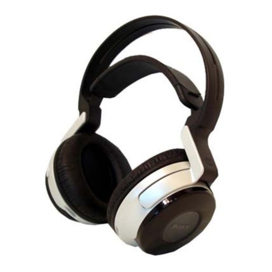
Photo : MDR-RF6000
TMR-RF5000
DP-RF6000
SPECIFICATIONS
General
Playback frequency range
Power requirements
Mass
Supplied accessories
Design and specifications are subject to change without notice.
12 – 22,000 Hz
Rechargeable nickel-metal hydride
battery (supplied) or commercially
available (size AA) alkaline batteries
Approx. 360 g (12.7 oz) (including the
supplied rechargeable nickel-metal
hydride battery)
Rechargeable nickel-metal hydride
battery
BP-HP2000 (2,100 mAh) (1)
Operating Instructions (this manual) (1)
WIRELESS STEREO HEADPHONES
US Model
Canadian Model
AEP Model
Korea Model
Advertisement
Table of Contents

Summary of Contents for Sony MDR-RF5000
-
Page 1: Specifications
Ver. 1.1 2006. 02 AEP Model Korea Model Photo : MDR-RF6000 MDR-RF5000 is the wireless stereo headphones section in MDR-RF5000K, and MDR-RF-6000 is the wireless headhones section in MDR-DS6000. COMPONENT NAME FOR MDR-RF5000K Wireless Stereo Headphones MDR-RF5000 Wireless Stereo Transmitter... -
Page 2: Table Of Contents
4-3. Head Band Assy Section ..........16 It is best to use only unleaded solder but unleaded solder may also be added to ordinary solder. ELECTRICAL PARTS LIST ........17 • Repaier MDR-RF5000 with TMR-RF5000, and repaier MDR- RF6000 with DP-RF6000. -
Page 3: General
MDR-RF5000/RF6000 SECTION 1 This section is extracted from instruction manual. GENERAL Part Descriptions 1 Ear pad (left) 6 TUNE/ID SET button Use this button when reception 2 Contact point deteriorates, or when using additional 3 Battery case headphones. This battery case is for the rechargeable... -
Page 4: Disassembly
MDR-RF5000/RF6000 SECTION 2 DISASSEMBLY • This set can be disassembled in the order shown below. 2-1. DISASSEMBLY FLOW 2-2. FRONT PLATE (L) ASSY 2-5. FRONT PLATE (R) ASSY (Page 4) (Page 6) 2-6. RX BOARD 2-3. BATT BOARD (Page 6) (Page 5) 2-7. -
Page 5: Batt Board
MDR-RF5000/RF6000 2-3. BATT BOARD 1 Remove the solder at 10 places. solder to SW board natural to RX board green BATT board black solder 2 screw (+B2.6) 3 two screws (+B2.6) 5 BATT board 2-4. HOUSING (L) ASSY 1 housing (L) assy... -
Page 6: Front Plate (R) Assy
MDR-RF5000/RF6000 2-5. FRONT PLATE (R) ASSY 4 Remove the solder at 2 places. Note for installation : Solder a red lead with there is marking. driver (R-CH) driver (R-CH) marking marking natural natural from RX board from RX board 2 three screws (+B2.6) -
Page 7: Housing (R) Assy
MDR-RF5000/RF6000 2-7. HOUSING (R) ASSY 1 housing (R) assy... -
Page 8: Diagrams
MDR-RF5000/RF6000 SECTION 3 DIAGRAMS • Note for Printed Wiring Boards and Schematic Diagrams Note on Schematic Diagrams. Note on Printed Wiring Boards. • All capacitors are in µF unless otherwise noted. (p: pF) 50 WV or • X : parts extracted from the component side. -
Page 9: Block Diagrams
MDR-RF5000/RF6000 3-1. BLOCK DIAGRAM ANT2301 ANT2302 IC2301 POWER AMP ANT 1 L-CH OUT SP2001 ANT 2 VO2 5 Q2301 +2.4V MUTE IC2302 POWER AMP R-CH OUT SP2002 RX-RF VO2 5 BLOCK MUTE Q2302 MUTE +2.4V CH/ID SYNC SW S2301 TUNE/ID SET... -
Page 10: Printed Wiring Boards- Batt, Switch Boards
MDR-RF5000/RF6000 :Uses unleaded solder. 3-2. PRINTED WIRING BOARD – BATT, SWITCH BOARDS – BATT BOARD (SIDE A) BATT BOARD (SIDE B) SWITCH BOARD (31) (41) 1-868-124- RECHARGEABLE BATTERY PACK (Ni-MH) BP-H2000 2.4V DRY BATTERY SIZE "AA" BOARD (IEC DESIGNATION LR6) (Page 11) 2PCS. -
Page 11: Printed Wiring Boards- Rx Board
MDR-RF5000/RF6000 3-3. PRINTED WIRING BOARD – RX BOARD– :Uses unleaded solder. RX BOARD (SIDE A) RX BOARD (SIDE B) RX-RF BLOCK TUNE/ID SET BATT BOARD (Page 10) • Semiconductor 1-868-116- Location TUNE/ID SET 1-868-116- (31) (41) Ref. No. Location (31) -
Page 12: 3-4. Schematic Diagram
MDR-RF5000/RF6000 Ver. 1.1 3-4. SCHEMATIC DIAGRAM • See page 13 for IC Block Diagrams. - Page 13 MDR-RF5000/RF6000 • IC Block Diagrams IC2504 LTC3401EMS#TR SHUTDOWN 10 SHDN SLEEP BURST MODE CONTROL LOGIC 1.25V CURRENT COMP ERROR ZERO SLOPE † COMP 1.6A CURRENT LIMIT VOUT MODE ANTICROSS COND 1.25V PGOOD ANTIRING SENSE IC2505 XC6219B282MR VOLTAGE REFERENCE CURRENT LIMIT...
-
Page 14: Exploded Views
MDR-RF5000/RF6000 Ver. 1.1 SECTION 4 EXPLODED VIEWS NOTE: • The mechanical parts with no reference number • -XX, -X mean standardized parts, so they may in the exploded views are not supplied. have some differences from the original one. •... -
Page 15: Housing (R) Assy Section
MDR-RF5000/RF6000 Ver. 1.1 4-2. HOUSING (R) ASSY SECTION Ref. No. Part No. Description Remarks Ref. No. Part No. Description Remarks 2-637-873-01 PAD, EAR 2-645-639-01 GUIDE, LIGHT 3-253-143-01 SCREW (B2.6), (+) P TAPPING 2-645-640-01 BUTTON, SYNC (RF6000) A-1134-595-A FRONT PLATE (R) ASSY... -
Page 16: Head Band Assy Section
MDR-RF5000/RF6000 Ver. 1.1 4-3. HEAD BAND ASSY SECTION (including 102, 103, 104) not supplied Ref. No. Part No. Description Remarks Ref. No. Part No. Description Remarks A-1179-102-A HEAD BAND ASSY (RF5000: US, CND) 4-966-791-21 STOPPER (UPPER) A-1182-621-A HEAD BAND ASSY (RF6000) -
Page 17: Electrical Parts List
MDR-RF5000/RF6000 Ver. 1.1 SECTION 5 BATT ELECTRICAL PARTS LIST NOTE: • Due to standardization, replacements in the • RESISTORS When indicating parts by reference parts list may be different from the parts All resistors are in ohms. number, please include the board. - Page 18 MDR-RF5000/RF6000 Ver. 1.1 SWITCH Ref. No. Part No. Description Remarks Ref. No. Part No. Description Remarks C2321 1-162-964-11 CERAMIC CHIP 0.001uF R2352 1-216-821-11 METAL CHIP 1/10W C2322 1-107-826-11 CERAMIC CHIP 0.1uF R2371 1-216-833-11 METAL CHIP 1/10W R2383 1-216-853-11 METAL CHIP...
- Page 19 MDR-RF5000/RF6000 MEMO...
- Page 20 Also, clicking the version at the upper right on the revised page allows you to jump to the next revised page. Ver. Date Description of Revision 2006.01 2006.02 Addition of AEP and Korea models for MDR-RF5000/RF6000. Change of A-BAN for MDR-RF6000. (ECB44886)

