Table of Contents
Advertisement
Quick Links
ELECTRIC COMBINATION BOILER
(European Patent No: 1757678. Design Right Protected.)
TH9- 210U, TH9-250U, TH9-330U
TH12-210U, TH12-250U, TH12-330U
INCLUDES THERMAL SOLAR & WOOD BURNING STOVE WITH WATER JACKET APPENDIX
This product is suitable for connection to ~230-240V, 50Hz
INSTRUCTIONS FOR USE, INSTALLATION AND
SERVICING
The instructions consist of three parts; User, Installation and Servicing instructions, which include the guarantee registration
card.
The instructions are an integral part of the appliance and must, to comply with the current issue of the building, electrical
regulations and water by-laws, be handed to the user on completion of the installation.
GUARANTEE REGISTRATION
Thank you for installing a new Thermaflow product in your home.
Thermal innovations appliances, are manufactured to the very highest standards so we are pleased to offer our customers, a
comprehensive first year guarantee and a second year parts guarantee.
In the instruction envelope is to be found your guarantee registration card, which must be completed and returned to Thermaflow
Ltd or register your Thermaflow appliance for 1st year guarantee protection by calling the below number.
Our guarantee gives you peace of mind valuable protection against breakdown by covering the cost of-
All replacement parts
All labour charges
All call-out charges
THERMAFLOW LTD
31-39 Napier Court, Cumbernauld, Glasgow, G68 0LG
Customer services
Tel
+44 (0) 870 850 5207
Fax
+44 (0) 870 850 5208
Web
www.thermaflowheating.co.uk
Issue Number: 2b Issue date: February 2012
Copyright Notice
This document contains proprietary information protected by copyright, and this Manual and documentation are copyrighted. All rights are reserved. No part of this
document may be photocopied or reproduced by mechanical, electronic, or other means in any form without permission from Thermaflow Ltd.
Copyright Thermaflow Ltd 2006-12 -All rights reserved.
for all models with serial No beginning
TO BE LEFT WITH THE USER
MRK 2
MRK 2
4-
Advertisement
Table of Contents

Related Manuals for Thermaflow TH9-210U MRK 2

Summary of Contents for Thermaflow TH9-210U MRK 2
- Page 1 In the instruction envelope is to be found your guarantee registration card, which must be completed and returned to Thermaflow Ltd or register your Thermaflow appliance for 1st year guarantee protection by calling the below number.
-
Page 2: Table Of Contents
THERMAFLOW LTD | THERMAFLOW® ELECTRIC COMBINATION BOILER | Tel: 0870 850 5207 Contents Instructions General .................4 Draining & Filling ..................5 Manual Handling Guidance ..............5 TESTING & CERTIFICATION ..............5 THE UNIT LOCATION................5 Water Connections ...................6 PART1 – INSTRUCTIONS FOR USE ..............7 INTRODUCTION..................7... - Page 3 THERMAFLOW LTD | THERMAFLOW® ELECTRIC COMBINATION BOILER | Tel: 0870 850 5207 2.6.3 External Controls..................23 ELECTRICAL CONNECTIONS...............23 2.6.4 Supply cable connection [24 HR Supply] ..........23 2.6.5 Heating system controls .................23 2.6.6 Electrical Test..................24 2.6.7 Supply cable connection [Interrupted off peak supply] ......24 2.6.8 Electrical Test..................24...
-
Page 4: Instructions General
Thermaflow boiler. It is recommended that the Thermaflow has a safety and maintenance check on an annual basis. A pressure reducing valve must be fitted to the cold water inlet of the appliance if the incoming pressure exceeds 300kPA (3 Bar). -
Page 5: Draining & Filling
CAUTION: THE THERMAFLOW BOILER WORKS IN A PRESSURISED SYSTEM WHICH MUST ONLY BE DRAINED, REFILLED AND PRESSURISED BY A COMPETENT PERSON. There is a drain tap fitted to the Thermaflow boiler to drain the primary circuit within the boiler it is located at the bottom of the appliance. -
Page 6: Water Connections
THERMAFLOW LTD | THERMAFLOW® ELECTRIC COMBINATION BOILER | Tel: 0870 850 5207 The unit should be positioned in a manner that allows access to all components for future maintenance. If located in a cupboard the unit should be positioned with all components facing the entrance to allow elements to be replaced if required or any of the other components. -
Page 7: Part1 - Instructions For Use
To obtain service please call your installer or Thermaflow Ltd, using the telephone number on the appliance or at the front of this manual. Please be advised that the Thermaflow log book should be completed by the installation engineer on completion of commission and servicing. -
Page 8: Draining And Filling
YOU MUST CONTACT YOUR INSTALLER re-pressurise the system correctly. Replacement parts If replacements parts are required, contact your Installer, Service Company or Thermaflow Ltd. Please quote the name and model of your appliance. (Ref. Spare Parts List - section 1.8.1). -
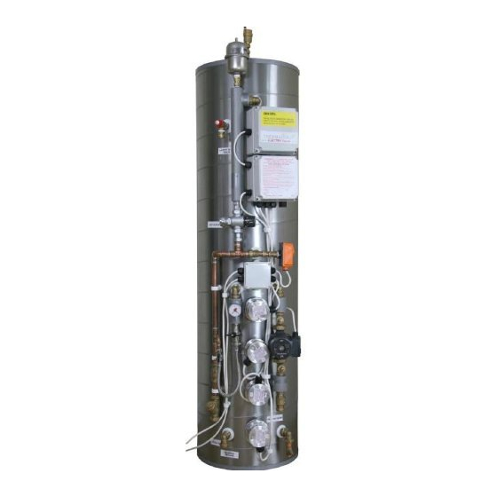
Page 9: Thermaflow Th Model Mk2
THERMAFLOW LTD | THERMAFLOW® ELECTRIC COMBINATION BOILER | Tel: 0870 850 5207 Thermaflow TH Model MK2 22mm single check valve External primary return 22mm single check valve external primary flow 22mm single check valve HW primary 22mm single check valve CH primary... -
Page 10: Table 1.8.1 [Data]
THERMAFLOW LTD | THERMAFLOW® ELECTRIC COMBINATION BOILER | Tel: 0870 850 5207 TABLE 1.8.1 [DATA] TH9-210U MRK 2 TH-250U MRK 2 TH-330U MRK 2 Lift Weight empty 60KG 70KG 75KG Total Weight boxed 70KG 80KG 85KG Weight Full 280KG 320KG 405KG Heating Flow &... -
Page 11: Part 2 - Installation
THERMAFLOW LTD | THERMAFLOW® ELECTRIC COMBINATION BOILER | Tel: 0870 850 5207 PART 2 – INSTALLATION 2.1.1 Sheet metal parts Warning: when installing or servicing this boiler care should be taken when handling the edges of metal parts to avoid any possibility of personal injury. -
Page 12: Electrical Supply
THERMAFLOW LTD | THERMAFLOW® ELECTRIC COMBINATION BOILER | Tel: 0870 850 5207 2.1.5 Electrical supply Means of disconnection of the electrical supply to the boiler must be incorporated in the fixed wiring in accordance with the wiring rules. E2000 Two isolators are required at the boiler when using an interrupted off peak supply eg. -
Page 13: Boilers In A Compartment
THERMAFLOW LTD | THERMAFLOW® ELECTRIC COMBINATION BOILER | Tel: 0870 850 5207 2.2.2 Boilers in a compartment Where the installation of the boiler will be in an unusual position, the current issue of BS 6798 gives detailed guidance on these requirements. -
Page 14: Clearances Allow For External Primary Heat Transfer Kit
Disconnect filling loop and seal both valves with suitable caps. 2.3.8 Corrosion inhibitor The maintenance of sufficient concentration of corrosion inhibitor in your Thermaflow system is vital to prevent corrosion. We would recommend sentinel X100, or equivalent. Dose appropriately according to... -
Page 15: Draining
THERMAFLOW LTD | THERMAFLOW® ELECTRIC COMBINATION BOILER | Tel: 0870 850 5207 2.3.9 Draining A draining tap must be provided at the lowest points of the system, which will allow the entire system to be drained. The boiler has a drain tap fitted for draining of the primary circuit. -
Page 16: Safety Valve Discharge
THERMAFLOW LTD | THERMAFLOW® ELECTRIC COMBINATION BOILER | Tel: 0870 850 5207 2.5.2 SAFETY VALVE DISCHARGE It must not discharge above an entrance or window or any type of public access. The position of the discharge outlet shall be visible to the occupants and shall be positioned away from any electrical devices. -
Page 17: Electrical Supply
THERMAFLOW LTD | THERMAFLOW® ELECTRIC COMBINATION BOILER | Tel: 0870 850 5207 2.6.1 ELECTRICAL SUPPLY IMPORTANT If the boiler is wired to the Scottish Power Domestic & Economy 200 tariff, it requires two separate ~230- 240V power supplies. A (24HR) supply for controls and an interruptible supply for the boiler. (Off Peak power supply if it is available diagram 2.6.1... - Page 18 THERMAFLOW LTD | THERMAFLOW® ELECTRIC COMBINATION BOILER | Tel: 0870 850 5207 2.6.2b OFF-PEAK & 24 HR WIRING CIRCUITS ~240VAC SUPPLY IF E10 – Supply to controls comes from 6A MCB in top control IF Scottish Power 6A 100A E2000 tariff –...
-
Page 19: Off-Peak Timer & Wiring Circuit
THERMAFLOW LTD | THERMAFLOW® ELECTRIC COMBINATION BOILER | Tel: 0870 850 5207 2.6.2c OFF-PEAK TIMER & WIRING CIRCUIT OFF PEAK TIMER The Off Peak Control allows you to time the boiler to charge during the reduced rate periods on wet electric central heating tariffs... -
Page 20: Solid Fuel & Solar Wiring Circuits
THERMAFLOW LTD | THERMAFLOW® ELECTRIC COMBINATION BOILER | Tel: 0870 850 5207 2.6.2d SOLID FUEL & SOLAR WIRING CIRCUITS Wiring Circuit & Equipment when linking thermal solar to the Thermaflow boiler Solar Controller Thermaflow Solar Relay on Boiler Common L... -
Page 21: Solid Fuel & Solar Combined Wiring Circuit
THERMAFLOW LTD | THERMAFLOW® ELECTRIC COMBINATION BOILER | Tel: 0870 850 5207 2.6.2e SOLID FUEL & SOLAR COMBINED WIRING CIRCUIT Wiring Circuit & Equipment when linking All Connections are ~240 VAC both thermal solar and a wood burning stove to the Thermaflow boiler 0-90 °C Control... -
Page 22: Solid Fuel Kit Wiring Circuit
THERMAFLOW LTD | THERMAFLOW® ELECTRIC COMBINATION BOILER | Tel: 0870 850 5207 2.6.2f SOLID FUEL KIT WIRING CIRCUIT Wiring diagram and additional equipment required All Connections are when linking a solid fuel appliance to the ~240 VAC Thermaflow boiler 0-50°C Control... -
Page 23: External Controls
THERMAFLOW LTD | THERMAFLOW® ELECTRIC COMBINATION BOILER | Tel: 0870 850 5207 2.6.3 External Controls diagram 2.6.2b External heating controls should be connected to the appropriate terminals numbered in WARNING: ALL EXTERNAL CONTROLS MUST NOT BE TAKEN FROM ANY OTHER POWER SUPPLY OTHER THAN VIA THE 3 AMP FUSED ISOLATING SWITCH MENTIONED ABOVE. -
Page 24: Electrical Test
Scottish & Southern Energy has an E10 wet electric heating tariff Other areas offer their own tariffs, which may be viable for economic operation. It is advisable to use the Thermaflow off-peak control when using off-peak tariffs other than the... -
Page 25: Commissioning
THERMAFLOW LTD | THERMAFLOW® ELECTRIC COMBINATION BOILER | Tel: 0870 850 5207 Scottish Power Domestic and Economy 2000 tariff as it reduces running costs substantially. 2.7 Commissioning 2.7.1 Filling domestic water circuit Check that the boiler is isolated from the electrical supply, at both external isolators. -
Page 26: Heating System Commissioning
THERMAFLOW LTD | THERMAFLOW® ELECTRIC COMBINATION BOILER | Tel: 0870 850 5207 2.7.5 Heating system commissioning Make sure the boiler and heating system is completely full of water. (SEE ABOVE SECTION 7.2) Turn on both 24Hr & Interrupted power supplies. Allow approximately 120 - 300 minutes to bring the boiler up to temperature (depending on model). -
Page 27: Part 3 - Servicing
THERMAFLOW LTD | THERMAFLOW® ELECTRIC COMBINATION BOILER | Tel: 0870 850 5207 PART 3 - SERVICING 3.1. Fault Finding MUST BE CARRIED OUT BY A PERSON COMPETENT TO DO SO Before trying to operate the boiler make sure that: The heating system pressure is at 150 KPA (1.5 Bar) when the system is COLD and 200 KPA (2.0 Bar) when the system is at maximum temperature. -
Page 28: Fault: No Domestic Hot Water Or Central Heating
THERMAFLOW LTD | THERMAFLOW® ELECTRIC COMBINATION BOILER | Tel: 0870 850 5207 3.1.1 Fault: No domestic hot water or central heating Is there ~230-240V at the 24HR supply? Check Fuse, MCB or Meter for correct operation Is there ~230-240V at the off peak supply? Check Fuse or MCB Is system pressure above 150 KPA (1.5 Bar)? -
Page 29: Fault: No Central Heating, But Hot Water At Taps
THERMAFLOW LTD | THERMAFLOW® ELECTRIC COMBINATION BOILER | Tel: 0870 850 5207 3.1.2 Fault: No central heating, but hot water at taps Is the off peak control in the on position? Turn on both channels Is there continuity through low pressure switch? -
Page 30: Fault: Central Heating But No Hot Water At Taps
THERMAFLOW LTD | THERMAFLOW® ELECTRIC COMBINATION BOILER | Tel: 0870 850 5207 3.1.3 Fault: CENTRAL HEATING BUT No hot water at taps Is the automatic air eliminator on top of the boiler in the Open the small screw cap on top of the... -
Page 31: Maintenance
The pressure can be accurately checked with the pressure relieved on the other side of the diaphragm. To do this, isolate the water supply to the Thermaflow boiler and open a hot tap. Water will run for a few seconds then stop. -
Page 32: Checking The Concentration Of Corrosion Inhibitor
3.2.5 Checking the concentration of corrosion inhibitor We would recommend Sentinel X100, or equivalent. Dose appropriately according to the size of the Thermaflow and central heating system volume combined and in accordance with the inhibitor manufacturer’s guidelines. 3.2.6 Preventing pump seizure in summer To prevent seizure of the central heating pump we recommend you turn the central heating on for 30 seconds or so every few weeks throughout the summer. -
Page 33: Checking The Heating Elements
If the thermostat continues to fail in an overheat condition a fault may have occurred in one or more of the control thermostats within the heating elements. Take note of which one it is and contact Thermaflow Ltd for spares and advice. The second is also a manual re-set over temperature thermostat and is fitted on the boiler. -
Page 34: Solar Thermal Linked Into The Thermaflow
THERMAFLOW LTD | THERMAFLOW® ELECTRIC COMBINATION BOILER | Tel: 0870 850 5207 4.1.1 SOLAR THERMAL LINKED INTO THE THERMAFLOW . Solar Panels . Solar Panel Flow Pipe . Solar Pump Station . Solar Panel Return Pipe . Solar Expansion Vessel . -
Page 35: Solid Fuel System Linked Into Thermaflow
THERMAFLOW LTD | THERMAFLOW® ELECTRIC COMBINATION BOILER | Tel: 0870 850 5207 4.1.2 SOLID FUEL SYSTEM LINKED INTO THERMAFLOW FE Tank For illustration purposes only Gravity Radiator Supply Manual Reset H/L Thermostats Temperature Control Th ermostat Set 70˚C Temperature Control Th... -
Page 36: External Primary Heat Transfer Equipment
THERMAFLOW LTD | THERMAFLOW® ELECTRIC COMBINATION BOILER | Tel: 0870 850 5207 4.1.3 EXTERNAL PRIMARY HEAT TRANSFER EQUIPMENT External Primary Heat Transfer Equipment Flow connection on Thermaflow boiler Thermal Solar Circuit Flow from Flow from Solar Wood Burner Return from...