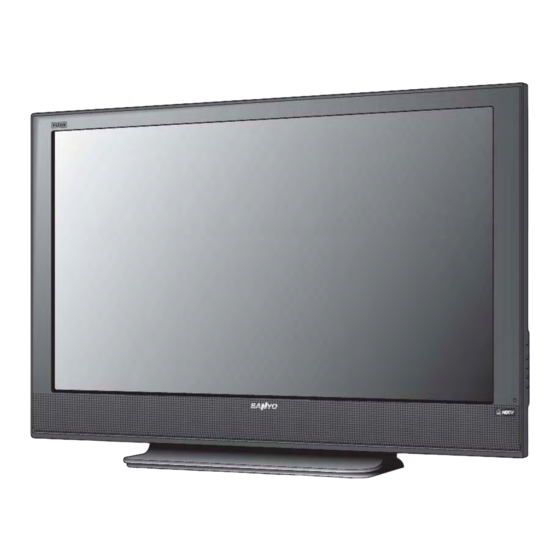
Sanyo DP50747 Service Manual
Sanyo remote control plasma color television
Hide thumbs
Also See for DP50747:
- Service manual (62 pages) ,
- Owner's manual (52 pages) ,
- Owner's manual (52 pages)
Table of Contents
Advertisement
SERVICE MANUAL
Servicing should be performed by only trained and qualified service personnel.
Contents
Safety Instructions . . . . . . . . . . . . . . . . . . 2
Service Adjustments . . . . . . . . . . . . . 3 - 4
Power Failure Circuit . . . . . . . . . . . . . . . . 5
Mechanical Disassemblies . . . . . . . . 6 - 10
Chassis Electrical Parts List . . . . . . 11 - 24
Cabinet Parts List . . . . . . . . . . . . . . . . . . 25
Locations . . . . . . . . . . . . . . . . . . . 26 - 28
Block Diagrams . . . . . . . . . . . . . . . . 29 - 40
Troubleshooting Flow Charts . . . . . 41 - 43
Control Port Functions. . . . . . . . . . . 44 - 45
Schematic Notes . . . . . . . . . . . . . . . . . . . 46
Pin Layouts. . . . . . . . . . . . . . . . . . . . . . . . 47
Capacitor and Resistor Codes . . . . . . . . 48
Schematic Diagrams . . . . . . . . . . . . 49 - 52
DP50747, J4DE, PRODUCT CODE 111010304
with a double "Z" is a registered trademark
of Sanyo Manufacturing Corporation.
Remote Control Plasma
Color Television
AS
FILE NO.
DP50747
ORIGINAL VERSION
Chassis No. P50747-00
NOTE: Match the Chassis No. on
the unit's back cover with
the Chassis No. in the
Service Manual.
If the Original Version
Service Manual Chassis
No. does not match the
unit's, additional Service
Literature is required. You
must refer to "Notices" to the
Original Service Manual
prior to servicing the unit.
Specifications
Power Rating . . . . . . . . . . . . . . . . . . . . . . . . 120VAC
Antenna Input Impedance . . . . . . . . . . . . . . . . . 75Ω
Receiving Channel . . . . . . . . . . . . . . . . 2 - 13 (VHF),
01, 14-94, 95-125 (CATV)
Remote Ready . . . . . . . . . . 32 Key Remote Control
Sound Output . . . . . . . . . . . . . . . . . . . . . . 7.0 W/CH
Intermediate Frequency
Picture IF Carrier . . . . . . . . . . . . . . . . . . 45.75MHz
Sound IF Carrier . . . . . . . . . . . . . . . . . . 41.25MHz
Color Sub Carrier . . . . . . . . . . . . . . . . . 42.17MHz
Cabinet Dimensions
Width . . . . . . . . . . . . . . . . . . . . . . . . . . . . 1255mm
Height . . . . . . . . . . . . . . . . . . . . . . . . . . . . 846mm
Depth including base . . . . . . . . . . . . . . . . 281mm
REFERENCE No.
(U.S.A.)
(CANADA)
460W, 4.6A (Max)
UHF/VHF/CATV
Digital
14 - 69 (UHF),
1-99 (Digital)
SM
780141
Advertisement
Table of Contents

Related Manuals for Sanyo DP50747


Summary of Contents for Sanyo DP50747
-
Page 1: Table Of Contents
Height ......846mm Depth including base ....281mm DP50747, J4DE, PRODUCT CODE 111010304 REFERENCE No. -
Page 2: Safety Instructions
SAFETY INSTRUCTIONS SAFETY PRECAUTIONS READING SHOULD NOT EXCEED 750 mV. AC VOLTMETER WARNING: The chassis of this receiver has a floating (5000 ohms per volt or more sensitivity) ground with the potential of one half the AC line voltage in respect to earth ground. -
Page 3: Service Adjustments
SERVICE ADJUSTMENTS GENERAL This set has an On-screen Service Menu system included in Volume – the CPU that allows remote operation for most of the ser- Enter Service Menu vice adjustments. ON-SCREEN SERVICE MENU SYSTEM 1. Enter the Service Menu: •... - Page 4 ON-SCREEN SERVICE MENU Table 1. ON-SCREEN SERVICE MENU When IC802 (EEPROM) is replaced, check the bus data to confirm they are the same as below. See page 3 for On-Screen Service Menu access and adjustments. Title Initial Data Note Volume setup inspection Option 1 Data Option 2 Data 1R00...
-
Page 5: Power Failure Circuit
POWER FAILURE CIRCUIT Check the following if the unit is turned off by the power This unit is equipped with a Power Failure Detector function failure detector. included in the CPU which checks for an abnormal condi- tion in the chassis power supplies. 1. -
Page 6: Mechanical Disassemblies
MECHANICAL DISASSEMBLY ATTENTION This PDP TV uses several different kinds of screws. Using the correct screw is required to prevent damage. The gasket is provided to prevent interference to other radio and television receivers. The gasket must be returned to its previous position after servicing. Lead wires must be redressed to previous positions after servicing. - Page 7 BOARD AND SPEAKER LOCATIONS 1: Main Board 3: Control Board 2: Sub-Power and Filter Board 4: Speakers SHIELD AND TERMINAL BASE REMOVAL Remove 5 screws (D:3X8, 3pcs, E:4X8, 2pcs) to take the shield off. Remove 5 screws (F:4X14, 2pcs, G:3X8, 3pcs) to take the terminal base off. —...
- Page 8 MECHANICAL DISASSEMBLY (CONT.) BOARD REMOVAL 1: Main Board Removal 3: Control Board Removal Remove 5 screws (H:3X8) to take the main board Remove 2 screws (A:4X14) to take the control off. board off. 2: Sub-Power and Filter Board Removal Remove 9 screws (H:3X8, 6pcs, I:3X8, 2pcs, J:4X10, 1pc) to take the sub-power and filter board off.
- Page 9 FILTER GLASS AND SPEAKER REMOVAL (Cont.) 3. Remove 13 screws (4X14) to take the shield plates (top, bot- tom, R/L sides) with the filter glass off. 4. Remove 4 screws (4X!4) to take off each speaker — 9 —...
- Page 10 MECHANICAL DISASSEMBLY (CONT.) PANEL MODULE REMOVAL 1. Disconnect the following socket connections; PDP Module Power Unit ~ Sub-power and Filter Board: CN8003, CN8004 PDP Module Logic Unit ~ Main Board: CN8001 2. Remove 8 screws (4X14) from the panel Mounting Brackets and take the panel module off.
-
Page 11: Chassis Electrical Parts List
CHASSIS ELECTRICAL PARTS LIST CAUTION: To Protect against electrical shock and for continued product safety, refer to SAFETY PRECAUTIONS, and PRODUCT SAFETY NOTICE on Page 2. PRODUCT SAFETY NOTICE PRODUCT SAFETY SHOULD BE CONSIDERED WHEN A REPLACEMENT IS MADE IN ANY AREA OF A RECEIVER. COMPONENTS INDICATED BY A IN THIS PARTS LIST AND THE SCHEMATIC DIAGRAM DESIGNATE COMPONENTS IN WHICH SAFETY CAN BE OF SPECIAL SIGNIFICANCE. - Page 12 Schematic Schematic Part No. Part No. Description Description Location Location CAPACITORS C1000 CK1H104ZLZFNG CERAMIC 0.1U Z C1001 CEXLB1H100VDN ELECT 10U M C001 CPXLB1C100YAN NP-ELECT 10U M CPXLB1C100ZAN NP-ELECT 10U M CEXLB1H100WAN ELECT 10U M C1002 CEXLB1H100VDN ELECT 10U M C002 CK1H104ZLZFNG CERAMIC 0.1U Z...
- Page 13 Schematic Schematic Part No. Part No. Description Description Location Location C1643 CEXLB1C101VDN ELECT 100U M C5522 CK1A105ZLZFNG CERAMIC 1U Z CEXLB1C101WAN ELECT 100U M C5523 CK1A105ZLZFNG CERAMIC 1U Z C1652 CEXLB1E102VDN ELECT 1K U M C5529 CK1H104ZLZFNG CERAMIC 0.1U Z C1653 CK1H104ZLZFNG CERAMIC...
- Page 14 Schematic Schematic Part No. Part No. Description Description Location Location C5709 CK1H104ZLZFNG CERAMIC 0.1U Z C6120 CK1H104ZLZFNG CERAMIC 0.1U Z C5721 CK0J475KLZBNG CERAMIC 4.7U K 6.3V C6122 CK1A105ZLZFNG CERAMIC 1U Z C5722 CK1H104ZLZFNG CERAMIC 0.1U Z C6124 CK1H103ZLZFNG CERAMIC 0.01U Z C5724 CK1H104ZLZFNG CERAMIC...
- Page 15 Schematic Schematic Part No. Part No. Description Description Location Location C6235 CK1H104ZLZFNG CERAMIC 0.1U Z C6322 CC1H151JLZCNG CERAMIC 150P J C6236 CK1H104ZLZFNG CERAMIC 0.1U Z C6325 CC1H151JLZCNG CERAMIC 150P J C6237 CK1H104ZLZFNG CERAMIC 0.1U Z C6326 CC1H151JLZCNG CERAMIC 150P J C6238 CK1H104ZLZFNG CERAMIC...
- Page 16 Schematic Schematic Part No. Part No. Description Description Location Location IC1251 QCD4052BNSR-P IC CD4052BNSR L1654 RGFR000ZTAANL MT-GLAZE0.000 ZA 1/10W QTC4052BF---P IC TC4052BF-EL L1655 RGFR000ZTAANL MT-GLAZE0.000 ZA 1/10W IC1600 QLA5774MPE--P IC LA5774MP-DL-E L1670 RGFR000ZTAANL MT-GLAZE0.000 ZA 1/10W IC1610 QPQ070XNA1ZPP IC PQ070XNA1ZPH L1673 RGFR000ZTAANL MT-GLAZE0.000 ZA 1/10W...
- Page 17 Schematic Schematic Part No. Part No. Description Description Location Location L5516 RGFR000ZTAANL MT-GLAZE0.000 ZA 1/10W L6189 RGFR000ZTAANL MT-GLAZE0.000 ZA 1/10W L5521 RGFR000ZTAANL MT-GLAZE0.000 ZA 1/10W L6201 RGFR000ZTAANL MT-GLAZE0.000 ZA 1/10W L5522 RGFR000ZTAANL MT-GLAZE0.000 ZA 1/10W L6202 RGFR000ZTAANL MT-GLAZE0.000 ZA 1/10W L5523 RGFR000ZTAANL MT-GLAZE0.000 ZA 1/10W...
- Page 18 Schematic Schematic Part No. Part No. Description Description Location Location TRANSISTORS Q1202 T2SC2412K-R-P TR 2SC2412K-T-96-R T2SC2412K-S-P TR 2SC2412K-T-96-S Q101 T2SC2412K-R-P TR 2SC2412K-T-96-R T2SC2412K-S-P TR 2SC2412K-T-96-S T2SC2812-L7-P TR 2SC2812-L7-TB T2SC2812N-L6P TR 2SC2812N-L6-TB T2SC2812-L6-P TR 2SC2812-L6-TB T2SC3928A1R-P TR 2SC3928A1R T2SC2812-L7-P TR 2SC2812-L7-TB T2SC2812N-L6P TR 2SC2812N-L6-TB T2SC3928A1S-P...
- Page 19 Schematic Schematic Part No. Part No. Description Description Location Location Q1606 T2SC2412K-R-P TR 2SC2412K-T-96-R Q5802 T2SA1037AK-RP TR 2SA1037AK T146 R T2SC2412K-S-P TR 2SC2412K-T-96-S T2SA1037AK-SP TR 2SA1037AK T146 S T2SC2812-L6-P TR 2SC2812-L6-TB T2SA1037K-R-P TR 2SA1037K-T-96-R T2SC2812-L7-P TR 2SC2812-L7-TB T2SA1037K-S-P TR 2SA1037K-T-96-S T2SC2812N-L6P TR 2SC2812N-L6-TB T2SA1179-M6-P...
- Page 20 Schematic Schematic Part No. Part No. Description Description Location Location Q6250 T2SA1179-M7-P TR 2SA1179-M7-TB R809 RGF4701JTCANL MT-GLAZE 4.7K JA 1/10W (Cont.) T2SA1179N-M6P TR 2SA1179N-M6-TB R811 RGF1002JTCANL MT-GLAZE 10K JA 1/10W T2SA1235A1E-P TR 2SA1235A1E R812 RGF1000JTCANL MT-GLAZE 100 JA 1/10W T2SA1235A1F-P TR 2SA1235A1F R814 RGFR000ZTCANL...
- Page 21 Schematic Schematic Part No. Part No. Description Description Location Location R1001 RGF75R0JTCANL MT-GLAZE 75 JA 1/10W R1206 RGF1002JTCANL MT-GLAZE 10K JA 1/10W R1002 RGF47R0JTCANL MT-GLAZE 47 JA 1/10W R1207 RGF1002JTCANL MT-GLAZE 10K JA 1/10W R1003 RGF75R0JTCANL MT-GLAZE 75 JA 1/10W R1208 RGF1002JTCANL MT-GLAZE...
- Page 22 Schematic Schematic Part No. Part No. Description Description Location Location R1819 RGF1002JTCANL MT-GLAZE 10K JA 1/10W R5544 RGF1000JTCANL MT-GLAZE 100 JA 1/10W R1820 RGF1002JTCANL MT-GLAZE 10K JA 1/10W R5545 RGF2201JTCANL MT-GLAZE 2.2K JA 1/10W R1821 RGF4701JTCANL MT-GLAZE 4.7K JA 1/10W R5546 RGF1002JTCANL MT-GLAZE...
- Page 23 Schematic Schematic Part No. Part No. Description Description Location Location R5907 RGF1002JTCANL MT-GLAZE 10K JA 1/10W R6238 RGF33R0JTCANL MT-GLAZE 33 JA 1/10W R5908 RGF2202JTCANL MT-GLAZE 22K JA 1/10W R6240 RGFR000ZTCANL MT-GLAZE 0.000 ZA 1/10W R5951 RGF1001JTCANL MT-GLAZE 1K JA 1/10W R6241 RGFR000ZTCANL MT-GLAZE...
- Page 24 Schematic Schematic Part No. Part No. Description Description Location Location R6502 RGF5R60JTCANL MT-GLAZE 5.6 JA 1/10W R6580 RGFR000ZTCANL MT-GLAZE 0.000 ZA 1/10W R6503 RGF5R60JTCANL MT-GLAZE 5.6 JA 1/10W R6581 RGF1001JTCANL MT-GLAZE 1K JA 1/10W R6504 RGF5R60JTCANL MT-GLAZE 5.6 JA 1/10W R6582 RGF1002JTCANL MT-GLAZE...
-
Page 25: Cabinet Parts List
RC-BATTERY LID 1AA2DES0916-- DEC SHEET AV W601 1AV4W11B29300 CORD, POWER 1AA2BUM0529-- BUTTON UNITED 1AV4W11B17100 CORD, POWER 1AA2DEM0444-- DEC IND 1AA2SDM0173-- STAND COVER 1AA2SDF0047-- STAND BASE (2) 1AA2DES0917-- DEC SHEET HDTV 1AV2BAAS015AA BADGE, SANYO 1AA2DES0712-F DEC SHEET, VIZON — 25 —... -
Page 26: Component And Testpoint Locations
COMPONENT AND TESTPOINT LOCATIONS MAIN BOARD PARTS SIDE R866 K_DL R1629 K_DEBUG K1000 R842 R1633 R843 R892 R1635 D9100 R844 R9107 K9100 R864 R1684 L2014 C701 R865 C683 C825 R1648 R1637 R1688 R863 L1605 IC001 R858 R1681 IC001A RB6355 R872 R1634 IC001B R6264... - Page 27 MAIN BOARD FOIL SIDE L1723 L1722 SC1508 K9100 L2017 L1721 R1515 R017 R9108 L2016 R1517 C011 K_DL IC001 L1713 R1518 C842 R1805 R9105 K_DEBUG C694 IC001A C002 R1516 SC1805 IC001B R9101 L1716 SC1509 K1000 IC001C L6704 R1807 R9106 IC001D SC1806 C689 R1803 C010...
-
Page 28: Locations
COMPONENT AND TESTPOINT LOCATIONS (Cont.) KEY BOARD PARTS SIDE SW1902 SW1903 SW1904 SW1905 L1901 SW1901 A1901 C1903 C1902 K19FRA D1901 A30C5 PWB,CONTROL,N4SG A1902 1AA4B10N2020A POWER CH_UP VOL_UP VOL_DOWN CH_DOWN D1902 KEY BOARD FOIL SIDE SW1905 SW1902 SW1904 SW1903 L1901 K19FRA R1907 SW1901 D1901... - Page 29 BLOCK DIAGRAM POWER LINES — 29 —...
-
Page 30: Block Diagrams
BLOCK DIAGRAM SIGNAL LINES — 30 —... - Page 31 IC BLOCK DIAGRAMS IC001, Audio AMP Standby Input amplifier + OUT1 IN 1 Output amplifier - OUT1 MUTE Vcc ground shorting protection circuit Load shorting protection circuit Thermal protection circuit + OUT2 IN 2 Output amplifier - OUT2 Input amplifier Ripple Filter IC1201, IC1251 Video and Audio Select...
- Page 32 IC BLOCK DIAGRAMS (CONT.) IC1600, DC to DC Converter IC1620, DC to DC Converter — 32 —...
- Page 33 IC1630, DC to DC Converter IC1640, DC to DC Converter — 33 —...
- Page 34 IC BLOCK DIAGRAMS (CONT.) IC5500 Screen Controller — 34 —...
- Page 35 IC5700, IC5720 DDR: Double Data Rate SDRAM — 35 —...
- Page 36 IC BLOCK DIAGRAMS (CONT.) IC6100, TS Demodulator — 36 —...
- Page 37 IC6200, A/D Converter — 37 —...
- Page 38 IC BLOCK DIAGRAMS (Cont.) IC6502, DVI / HDMI SWITCH (3.3V) VSADJ TMDS Drive 3~to~1 MUX TMDS Drive TMDS Drive (3.3V) TMDS Drive HPD1 HPD2 Control Logic HPD_SINK HPD3 SCL1 SCL_SINK SDA1 SDA_SINK SCL2 SDA2 SCL3 SDA3 — 38 —...
- Page 39 IC6551, HDMI MULTIPLEXER Same as above block — 39 —...
- Page 40 IC BLOCK DIAGRAMS (CONT.) IC6270, STEREO A/D CONVERTER AVDD CONTROL INTERFACE AGND SDATO LRCLK DIGITAL AUDIO FILTERS INTERFACE BCLK MCLK — 40 —...
-
Page 41: Troubleshooting Flow Charts
TROUBLESHOOTING FLOW CHARTS NO POWER fuse (F601) Check: open? Varistor (VA601),Sub Power & Filter Unit the voltage Check: Power Unit to "5V_STBY" line (PDP Module) supplied? All 0V (except '5V_STBY' line) the voltage to all lines Check: around supplied? CPU (IC801), IC (IC802), Crystal (X801), Power Unit (or the voltage to some lines is not supplied.) After a few seconds, the set will be switched off. - Page 42 TROUBLESHOOTING FLOW CHARTS (Cont.) NO AUDIO Is there Check: All Modes ? signal at speaker Speaker (L / R) terminal ? Is there Check: signal at IC001 2pin (L) Line: IC001 6pin - IC801 (CPU) 38pin (Mute) or 4pin (R) ? Parts: Around IC001 (Audio AMP.) Check: Parts: Around IC3200 (Audio Control)
- Page 43 NO VIDEO Check: RF (TV) only All Inputs? Line: A6100 4pin - Q101 - IC1201 2pin Parts: Around A6100 (TU_IF), Q101 AV1 only Check: Line: IC1201 1pin (Composite Video: CV) IC1201 5pin (S-Input: Y) IC1201 13pin - IC5500 Y3 (AV1: C) Check: AV2 only Line:...
-
Page 44: Control Port Functions
CONTROL PORT FUNCTIONS System Control (CPU : IC801) Pin Name Function I/O Description CVin Reserve GND (0Vdc) P70/INT0/TOLCP LINE OFF Detect AC Voltage Reduction (Normal: High) P71/INT1/TOHCP Reserve (Open) P72/INT2/TOIN Display Enable (Unused) P73/INT3/TOIN RC in RC Input Key in Key Input AFT S-Figure in AFT S-Figure Input... -
Page 45: Control Port Functions
CONTROL PORT FUNCTIONS (Cont.) System Control (CPU : IC801 Cont.) Pin Name Function I/O Description P12/SCK0 PDP/LCD Option Setting (PDP: High, LCD: Low) Panel Size 3 Panel size Panel Size 2 Panel size Panel Size 1 Panel size Panel Size 0 Panel size Reserve (Open) -
Page 46: Schematic Notes
SCHEMATIC DIAGRAMS NOTES ON SCHEMATIC DIAGRAMS 1. All resistance values in ohms K=1,000 M=1,000,000. 2. Resistors specified with resistance value are “1/6DJ. ” 3. Resistors specified with type of resistor, tolerence and resistance value are “1/4. ” 4. Unless otherwise noted on schematic, all capacitor values less than 1 are expressed in µF (Micro Farad), and the values more than 1 are in pF . -
Page 47: Pin Layouts
IC, DIODE, AND TRANSISTOR PIN LAYOUTS DIODES INTEGRATED CIRCUITS PHOTO COUPLERS TRANSISTORS TOP VIEW TOP VIEW MARK COUNT TERMINALS IN ARROW DIRECTION SIDE VIEW INFRARED EMITTING B ... BASE C ... COLLECTOR A..ANODE E ... EMITTER K..CATHODE CHIP TRANSISTORS CHIP RESISTORS TOP VIEW TOP VIEW 12 x 10 = 12K ohm... -
Page 48: Capacitor And Resistor Codes
Y ......Wire Wound C ......Solid D ......Carbon Film W ......Wire Wound For parts or service contact Sanyo Manufacturing Corporation P .O. Box 2000 3333 Sanyo Road Forrest City, Arkansas 72335-2000 March 2007 SMC Published in U.S.A. -
Page 49: Schematic Diagrams
MODEL DP50747 Chassis No. P50747-00 SCHEMATIC DIAGRAMS ELECTROSTATICALLY SENSATIVE DEVICES Many solid-state devices (especially Integrated Circuits) are Electrostatically Sensitive, and, therefore, require special handling techniques as described under 50 PLASMA DISPLAY PANEL “Servicing Electrostatically Sensitive Devices, ” on page two in this service literature. - Page 50 Chassis No. P50747-00 MODEL DP50747 SCHEMATIC DIAGRAMS ELECTROSTATICALLY SENSATIVE DEVICES Many solid-state devices (especially Integrated Circuits) are Electrostatically Sensitive, and, therefore, require special handling techniques as described under “Servicing Electrostatically Sensitive Devices, ” on page two in this service literature.
- Page 51 Chassis No. P50747-00 MODEL DP50747 SCHEMATIC DIAGRAMS ASSY, PWB, MAIN SCL_D TO IC6301 TO IC5500 SDA_D C1017 TO TUNER EM4.7LBVD IF_AGC IEC958 SHELD CASE 2 R1074 1/10GJ82C I2C0CLK K1003 R1075 TO IC5500 I2C0CLK 1/10GJ82C D3.3V I2C0DATA R1000 I2C0DATA 1/10 C1000...
-
Page 52: Schematic Diagrams
Chassis No. P50747-00 MODEL DP50747 SCHEMATIC DIAGRAMS ASSY, PWB, MAIN K6500 1/10GJ5.6C R6509 HDMI_RX2+ R6260 1/10GZ0C R6508 1/10GJ5.6C HDMI_RX2- 1/10GZ0C R6507 1/10GJ5.6C LVDS[30] HDMI_RX1+ R6527 KZ0.1 KZ0.1 KZ0.1 C5751 L5751 1/10GF4.7KC LVDS[28] R6526 C6508 C6507 C6506 35EM47LBVD 1/10GZ0.0 HDMI_RX1- C5752 D3.3V...