
Related Manuals for Sonance SONAMP DSP 2-150


Summary of Contents for Sonance SONAMP DSP 2-150
- Page 1 I N S T R U C T I O N M A N UA L SONAMP MULTI-CHANNEL POWER AMPLIFIER ® WITH DSP 2-150...
-
Page 2: Table Of Contents
SONAMP DSP 2-150 MULTI-CHANNEL POWER AMPLIFIER INSTRUCTION MANUAL TABLE OF CONTENTS Safety Introduction/Box Contents Front Panel/Rear Panel Amplifier Power Requirement Chart Connections and Volume Level Controls Protection Circuitry and LEDs Network Connection Instructions Quick Setup Page Advanced Room Correction VP10SUB & VP10SUB NC Installation... -
Page 3: Safety
You should always follow these basic safety precautions when using a marked change in performance. your Sonamp DSP 2-150, to reduce the risk of fire, electric shock, and injury to persons: • The amplifier has been dropped, or the enclosure damaged. - Page 4 SONAMP DSP 2-150 MULTI-CHANNEL POWER AMPLIFIER INSTRUCTION MANUAL I N S T R U C T I O N S I M P O R TA N T E S C O N C E R N A N T L A S É C U R I T É...
-
Page 5: Introduction/Box Contents
SONAMP DSP 2-150 MULTI-CHANNEL POWER AMPLIFIER INSTRUCTION MANUAL Introduction Unpacking Thank you for purchasing the Sonance Sonamp DSP 2-150 Save the carton and polystyrene inserts for future safe transport in amplifier. When properly installed, this amplifier will give you case the amplifier is moved or requires shipping for repair. -
Page 6: Front Panel/Rear Panel
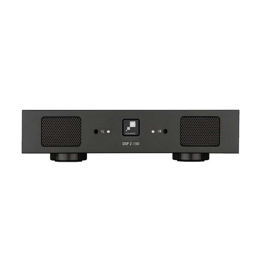
SONAMP DSP 2-150 MULTI-CHANNEL POWER AMPLIFIER INSTRUCTION MANUAL FIGURE 2: SONAMP DSP 2-150 MULTI-CHANNEL POWER AMPLIFIER FRONT PANEL DSP 2-150 Front Panel 1. Illuminated Power Button 2. Power, Active & Protection Indicator LED 3. Recessed Volume Level Control FIGURE 3: SONAMP DSP 2-150 MULTI-CHANNEL POWER AMPLIFIER BACK PANEL DSP 2-150 Rear Panel 8. -
Page 7: Rear Panel
The power switch turns the amplifier on and off. The DSP 2-150 amplifier has LINE INPUTS and loop OUTPUTS. When the Sonance logo on the power switch is lit solid white, the The loop outputs are non buffered, the maximum number of amplifier has power and is turned ON and ready to operate. -
Page 8: Amplifier Power Requirement Chart
15 amp or 20 amp wall outlet. IMPORTANT: DO NOT PLUG THE AMPLIFIER’S POWER CORD FIGURE 8: SONAMP DSP 2-150 LEFT, RIGHT LINE INPUTS INTO A CONVENIENCE OUTLET ON ANY OTHER AUDIO OR VIDEO COMPONENT. -
Page 9: Connections And Volume Level Controls
On the second page IN/OUT Settings go to the output setup area to FIGURE 12: SONAMP DSP 2-150 LEFT, RIGHT LINE INPUTS/OUTPUTS bridge mode and make your selections with the drop down buttons. 1. Use the left audio input when operating the amplifiers output in Volume Level Control bridged mode (see figure 10). -
Page 10: Protection Circuitry And Leds
FRONT VIEW Amplifier Channel Protection Indication DSP 2-150 On the front panel of the Sonamp DSP 2-150 amplifiers are dual color LEDs that illuminate to indicate the current operating status of each amplifier channel. -
Page 11: Network Connection Instructions
6. Network devices will show up and the amplifier will be named Sonance. 7. Open up Safari or Chrome for Mac. In the URL address window at the top enter the IP address of the Sonance DSP amplifier to configure. - Page 12 6. Select the Network from the list on the left. 7. Double click on the Sonance DSP amplifier, for example Sonance ‘2-150’ (192.168.1.222), you want to configure under “Other Devices”. A browser will automatically open and you will see the General Settings page.
-
Page 13: Quick Setup Page
SONAMP DSP 2-150 MULTI-CHANNEL POWER AMPLIFIER INSTRUCTION MANUAL Quick Setup Page If you will be using the Sonance DSP amplifier with a control system and only want to make basic changes to the software these instructions will guide you through the process. -
Page 14: Advanced Room Correction
DHCP On/Off DHCP ON / OFF is the first option in IP SETUP . All Sonance DSP series amplifiers ship with DHCP (Dynamic Host Connection Protocol) ON. In most installations DHCP should be left ON. If you are controlling the DSP series amplifier using IP then we suggest you turn DHCP OFF and use a static IP address. - Page 15 SONAMP DSP 2-150 MULTI-CHANNEL POWER AMPLIFIER INSTRUCTION MANUAL ID Amp Mode When the amplifier is connected to a network and an IP command is When flash power switch is turned ON the power button on the sent to the amplifier it will turn the amplifier on and off.
-
Page 16: Input Setup
This can eliminate DSP Preset any harsh transitions between sources with different output Apply any of the available Sonance DSP presets to each channel of voltages. Select the pull down menu in each channel to adjust the amplifier independently. - Page 17 SONAMP DSP 2-150 MULTI-CHANNEL POWER AMPLIFIER INSTRUCTION MANUAL Output Source Output Volume Source 1 Output volume ranges between -70 to 12. This is the primary source you will direct to the speakers. Any of the The default volume level controls are set at 0.
- Page 18 SONAMP DSP 2-150 MULTI-CHANNEL POWER AMPLIFIER INSTRUCTION MANUAL Assign Preset Test Signal software includes a built in pink noise generator. Output Name The pink noise signal can be used in conjunction with a real time These can be named Output 1L & Output 1R or room names such as analyzer to measure speakers.
- Page 19 SONAMP DSP 2-150 MULTI-CHANNEL POWER AMPLIFIER INSTRUCTION MANUAL Import Export Preset Copy Preset From / To the blue pull down menus allow you to pull a preset from All Presets one location and assign it to another location. Press green copy The green IMPORT EXPORT buttons allow you to save all 50 button to activate.
- Page 20 Parametric EQ All of the above output power ratings are when connected to an 8 ohm load. All Sonance DSP amplifier models feature a 10 band parametric EQ. Adjustments made to the EQ will be displayed on the Output Delay Frequency Response graph.
-
Page 21: Tilt Control
SONAMP DSP 2-150 MULTI-CHANNEL POWER AMPLIFIER INSTRUCTION MANUAL Crossover Tilt Control LP Xover / HP Xover The tilt controls are very sophisticated bass and treble control. This setting turns the high and low pass crossovers ON and OFF . By selecting a start frequency and level you can ramp the bass and or treble up or down. -
Page 22: Vp10Sub & Vp10Sub Nc Installation
SONAMP DSP 2-150 MULTI-CHANNEL POWER AMPLIFIER INSTRUCTION MANUAL DSP 2-150 AMPLIFIER WITH VP10SUB OR VP10SUB NC INSTALLATION 1. Read the DSP 2-150 Manual and Network Connection Many surround receivers and processor contain an automatic Instructions. calibration and equalization system. If yours does contain one, follow the manufacturer’s instructions on how to complete the... -
Page 23: Specifications
SONAMP DSP 2-150 MULTI-CHANNEL POWER AMPLIFIER INSTRUCTION MANUAL SPECIFICATIONS SONAMP DSP 2-150 Number of Channels 2 (1 stereo pair) Power Output - 8 ohms (Stereo) 150 Watts RMS per channel (all channels driven) Power Output - 4 ohms (Stereo) 224 Watts RMS per channel (all channels driven) -
Page 24: Warranty
SPECIFICALLY EXCLUDED. No one is authorized to make or modify any warranties on behalf of Sonance. The warranty stated above is the sole and exclusive remedy and Sonance’s performance shall constitute full and final satisfaction of all obligations, liabilities and claims with respect to the Product.