Table of Contents
Advertisement
Quick Links
Advertisement
Table of Contents

Related Manuals for Contec IPC-BX950T1-DC500


Summary of Contents for Contec IPC-BX950T1-DC500
- Page 1 IPC Series BOX-PC for IPC-BX950 Series User’s Manual CONTEC CO.,LTD.
-
Page 2: Check Your Package
Notes on using Windows XP None Embedded IPC-SLIB-01 *1 (User’s manual, Driver & Utility Soft Set) Recovery Media None Please confirm latest information on the CONTEC homepage though the user's manual is stored in IPC-SLIB-01. IPC-BX950T1 / IPC-BX950T2 / IPC-BX950T3 User’s manual... -
Page 3: Copyright
No part of this document may be copied or reproduced in any form by any means without prior written consent of CONTEC CO., LTD. CONTEC CO., LTD. makes no commitment to update or keep current the information contained in this document. -
Page 4: Table Of Contents
Table of Contents Check your package ..........................i Copyright..............................ii Trademarks ..............................ii Table of Contents ...........................iii INTRODUCTION About the Product ........................... 1 Features ............................1 Supported OS ........................... 2 Customer Support............................ 3 Web Site ............................3 Limited One-Year Warranty ........................3 How to Obtain Service.......................... - Page 5 Using Setup............................22 Getting Help ...........................22 In Case of Problems ........................22 A Final Note About Setup......................22 Main Menu.............................23 Setup Items .............................23 Standard CMOS Setup ..........................25 Main Menu Selections...........................26 IDE Adapters ..........................27 Advanced BIOS Features Setup......................28 CPU Feature............................29 Hard Disk Boot Priority ........................30 Virus Warning ..........................31 Advanced Chipset Features Setup......................36 PCI Express Root Port Function ......................39...
- Page 6 System Configuration ........................... 77 Component Function..........................78 LED: POWER, ACCESS, STATUS ..................... 78 DC Power Input Connector : DC-IN..................... 78 POWER SW ........................... 79 RESET SW............................. 79 Line out Interface : LINE OUT ..................... 79 Fast-Ethernet : LAN 1 - 2 ......................80 USB Ports ............................
- Page 7 IPC-BX950T1 / IPC-BX950T2 / IPC-BX950T3 User’s manual...
-
Page 8: Introduction
Embedded-type CPU and chip set have been adopted. The use of readily available parts ensures the ease of the use of the product. In addition, the use of a Contec-customized BIOS allows support to be provided at the BIOS level. -
Page 9: Supported Os
1. Introduction - Adoption of 945GME Chipset to allow the mounting of Intel Core Duo / Celeron M processor Adopting the Intel (R) 945GME, ICH7M-DH chip set, IPC-BX950T1 series achieve a high-level computing and drawing ability by using the 1.20GHz (FSB 533MHz) ultra low voltage Intel (R) Core (TM) Duo processor. -
Page 10: Customer Support
You can download updated driver software and differential files as well as sample programs available in several languages. Note! For product information Contact your retailer if you have any technical question about a CONTEC product or need its price, delivery time, or estimate information. Limited One-Year Warranty CONTEC products are warranted by CONTEC CO., LTD. -
Page 11: Safety Precautions
1. Introduction Safety Precautions Understand the following definitions and precautions to use the product safely. Safety Information This document provides safety information using the following symbols to prevent accidents resulting in injury or death and the destruction of equipment and resources. Understand the meanings of these labels to operate the equipment safely. - Page 12 To prevent corruption of files, always shutdown the OS before turning off this product. CONTEC reserves the right to refuse to service a product modified by the user. In the event of failure or abnormality (foul smells or excessive heat generation), unplug the power cord immediately and contact your retailer.
- Page 13 Cable TURN : 1 FCC PART 15 Class A Notice (Only IPC-BX950T1-DC500, IPC-BX950T1-DC556, IPC-BX950T2-DC400 and IPC-BX950T2-DC456) NOTE This equipment has been tested and found to comply with the limits for a Class A digital device, pursuant to part 15 of the FCC Rules. These limits are designed to provide reasonable protection against harmful interference when the equipment is operated in commercial environment.
-
Page 14: System Reference
LINE OUT: φ 3.5 Stereo mini jack Full-scale output level 1.5Vrms (Typ.), Dual 50mW Amplifier CF card slot CF CARD Type I x 2 bootable IPC-BX950T1-DC500 : -, IPC-BX950T2-DC400 : -, IPC-BX950T3-DC500 : -, IPC-BX950T1-DC55F : CF1 is IPC-BX950T2-DC45F : CF1 is... - Page 15 2. System Reference Table 2.1. Functional Specification < 2 / 2 > IPC-BX950T1-DC500 IPC-BX950T2-DC400 IPC-BX950T3-DC500 Model IPC-BX950T1-DC55F IPC-BX950T2-DC45F IPC-BX950T3-DC55F 1000BASE-T/100BASE-TX/10BASE-T RJ-45 connector x 2 (Wake On LAN support) Controller Intel 82573L Controller USB I/F 4ch (USB 2.0-compliant) Keyboard/mouse I/F None *3...
-
Page 16: Power Management Features
2. System Reference Table 2.2. Installation Environment Requirements IPC-BX950T1-DC500 IPC-BX950T2-DC400 IPC-BX950T3-DC500 Model IPC-BX950T1-DC55F IPC-BX950T2-DC45F IPC-BX950T3-DC55F (1) Vertical installation (power connector is downside) : 0 - 50 ° C (1) 0 - 45 ° C Operating temperature (2) Vertical and horizontal installation other than (2) 0 - 40 °... -
Page 17: Power Requirements
2. System Reference Power Requirements Your system requires a clean, steady power source for reliable performance of the high frequency CPU on the product, the quality of the power supply is even more important. For the best performance makes sure your power supply provides a range of 11.4 V minimum to 25.2 V maximum DC power source. Power Consumption For typical configurations, the CPU card is designed to operate with at least a 100W power supply. -
Page 18: Physical Dimensions
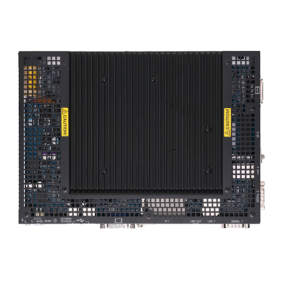
2. System Reference Physical Dimensions IPC-BX950T1-DC5xx, IPC-BX950T2-DC4xx, IPC-BX950T3-DC5xx 4-φ5 POWER HDMI 12 - 24VDC RESET STATUS CF 1 LINE OUT LAN 1 SERIAL 1 [mm] Figure 2.1. IPC-BX950T1-DC5xx, IPC-BX950T2-DC4xx, IPC-BX950T3-DC5xx IPC-BX950T1 / IPC-BX950T2 / IPC-BX950T3 User’s manual... - Page 19 2. System Reference IPC-BX950T1 / IPC-BX950T2 / IPC-BX950T3 User’s manual...
-
Page 20: Hardware Setup
3. Hardware Setup 3. Hardware Setup Before Using the BOX-PC for the First Time Follow the next steps to set up the BOX-PC: STEP1 By referring to the information in this chapter, install, connect and set the BOX-PC. STEP2 Connect cables. Connect the cable of necessary external devices, such as keyboard and a display, to this product using appropriate cables. -
Page 21: Hardware Setup
3. Hardware Setup Hardware Setup Before you start, be sure that the power is turned off. Remove only those screws that are explained. Do not move any other screw. Attaching the CF Attachment Fittings (1) After inserting a CF Card, fasten the bundled CF attachment fittings with a screw. Use the CF attachment fittings 2 when securing the USB and LINE OUT cables. -
Page 22: Attaching The Fg
3. Hardware Setup Attaching the FG (1) Use screws to attach the FG Figure 3.3. Attaching the FG CAUTION The FG pin of this product is connected to the GND signal of the DC power connector (DC-IN). Note that the connection cannot be cut off. IPC-BX950T1 / IPC-BX950T2 / IPC-BX950T3 User’s manual... -
Page 23: Fastening The Cable
3. Hardware Setup Fastening the Cable This product comes with clamps for fixing cables. Fastening the LINEOUT, USB Cable (1) The system unit has a hole for attaching cable clamp to CF attachment fittings 2. Using a cable clamp for a cable with lock-less connector, such as the LINEOUT and USB Cable, prevents the connector from being unplugged. -
Page 24: Installation Requirements
3. Hardware Setup Installation Requirements Be sure that the ambient temperature is within the range specified in the installation environment requirement by making space between the product and device that generates heat or exhaust air. IPC-BX950T1-DC5xx , IPC-BX950T2-DC4xx Installable directions at ambient temperature 0°C - +50°C : (2) Vertical installation (power connector is downside) Installable directions at ambient temperature 0°C - +45°C : All type of installation other than above (including diagonal installation) - Page 25 3. Hardware Setup Distances between the BOX-PC and Its Vicinity 50mm or more <*3> When installing to a 35mm-wide space between walls Follow the instructions below when installing the product to a 35mm-wide space between walls : *1 : This installation is only available when the power connector is downside.
- Page 26 3. Hardware Setup Ambient temperature In this product, the ambient temperature is decided from the multiple measurement points as shown below. When making use of the product, the air current should be adjusted to prevent that all the temperatures measured at the measurement points exceed the specified temperature. Measurement points <*1>...
- Page 27 3. Hardware Setup IPC-BX950T1 / IPC-BX950T2 / IPC-BX950T3 User’s manual...
-
Page 28: Bios Setup
4. BIOS Setup 4. BIOS Setup Introduction This chapter discusses Award’s Setup program built into the FLASH ROM BIOS. The Setup program allows users to modify the basic system configuration. This special information is then stored in battery-backed RAM so that it retains the Setup information when the power is turned off. The rest of this chapter is intended to guide you through the process of configuring your system using Setup. -
Page 29: Using Setup
4. BIOS Setup Using Setup In general, you use the arrow keys to highlight items, press <Enter> to select, use the PageUp and PageDown keys to change entries, press <F1> for help and press <Esc> to quit. The following table provides more detail about how to navigate in the Setup program using the keyboard. -
Page 30: Main Menu
4. BIOS Setup Main Menu Once you enter the Award BIOS CMOS Setup Utility, the Main Menu will appear on the screen. The Main Menu allows you to select from several setup functions and two exit choices. Use the arrow keys to select among the items and press <Enter>... - Page 31 4. BIOS Setup PnP / PCI Configuration This entry appears if your system supports PnP / PCI. Load Fail-Safe Defaults Use this menu to load the BIOS default values for the minimal/stable performance for your system to operate. Load Optimized Defaults Use this menu to load the BIOS default values that are factory settings for optimal performance system operations.
-
Page 32: Standard Cmos Setup
4. BIOS Setup Standard CMOS Setup Figure 4.2. Standard CMOS Setup The items in Standard CMOS Setup Menu are divided into 10 categories. Each category includes no, one or more than one setup items. Use the arrow keys to highlight the item and then use the <PgUp> or <PgDn>... -
Page 33: Main Menu Selections
4. BIOS Setup Main Menu Selections This table shows the selections that you can make on the Main Menu Table 4.2. Main Menu Selections Item Options Description Set the system date. Note that the ‘Day’ Date Month DD YYYY automatically changes when you set the date Time HH : MM : SS... -
Page 34: Ide Adapters
4. BIOS Setup IDE Adapters The IDE adapters control the CF card. Use a separate sub menu to configure each CF card. Use the legend keys to navigate through this menu and exit to the main menu. Use Table 4.3 to configure the hard disk. -
Page 35: Advanced Bios Features Setup
4. BIOS Setup Advanced BIOS Features Setup This section allows you to configure your system for basic operation. You have the opportunity to select the system’s default speed, boot-up sequence, keyboard operation, shadowing and security. Figure 4.3. Advanced BIOS Features Setup IPC-BX950T1 / IPC-BX950T2 / IPC-BX950T3 User’s manual... -
Page 36: Cpu Feature
4. BIOS Setup CPU Feature Figure 4.4. CPU Feature Press <Enter> to configure the settings relevant to CPU Feature. Table 4.4. CPU Features Selections Description Choice Delay Prior to Thermal Select the interval to setup the delay timer for CPU Thermal-Throuttling C1E Function CPU C1E Function Select. -
Page 37: Hard Disk Boot Priority
4. BIOS Setup Description Choice Execute Disable Bit When disabled, forces the XD feature flag to always return Hard Disk Boot Priority Figure 4.5. Hard Disk Boot Priority With the field, there is the option to choose, aside from the hard disks connected, “Bootable add-in Cards”... -
Page 38: Virus Warning
4. BIOS Setup Virus Warning When enabled, you receive a warning message if a program (specifically, a virus) attempts to write to the boot sector or the partition table of the hard disk drive. You should then run an anti-virus program. Keep in mind that this feature protects only the boot sector, not the entire hard drive. - Page 39 4. BIOS Setup Description Choice USB Device Wait When USB devices, which need longer time to be booted, are connected, the boot possibly can not be processed in normal condition. To address such cases, this setting specifies the waiting time for BIOS and delays the start of the access to the USB devices.
- Page 40 4. BIOS Setup Description Choice Third Boot Device The BIOS attempts to load the operating system from the devices in the sequence selected in these items. Boot Other Device The BIOS attempts to load the operating system from the devices in the sequence selected in these items. Boot Up NumLock Status Toggle between On or Off to control the state of the NumLock key when the system boots.
- Page 41 4. BIOS Setup Description Choice Typematic Rate Setting When Disabled, the following two items (Typematic Rate and Typematic Delay) are irrelevant. Keystrokes repeat at a rate determined by the keyboard controller in your system. When Enabled, you can select a typematic rate and typematic delay.
- Page 42 4. BIOS Setup Description Choice APIC Mode APIC stands for Advanced Programmable Interrupt Controller. Note : This item is show only MPS Version Control For OS Use the Multiprocessor Specification (MPS) for OS option to specify the MPS version to be used. MPS version 1.4 added extended configuration tables to improve support for multiple PCI bus configurations and improve future expandability.
-
Page 43: Advanced Chipset Features Setup
4. BIOS Setup Advanced Chipset Features Setup Figure 4.6. Advanced Chipset Features Setup This section allows you to configure the system based on the specific features of the installed chipset. This chipset manages bus speeds and access to system memory resources, such as DRAM and the external cache. - Page 44 4. BIOS Setup Description Choice CAS Latency Time When synchronous DRAM is installed, the number of clock cycles of CAS latency depends on the DRAM timing. Do not reset this fild from the default value specified by the system designer. You can select CAS latency time in HCLK of 3/4/5/6 or Auto.
- Page 45 4. BIOS Setup Description Choice System Memory Frequency This item sets the main memory frequency. When you use an external graphics card, you can adjust this to enable the best performance for your system. SLP_S4# Assertion Width Allows you to set the SLP_S4# assertion width. The default setting is 1 to 2 Sec.
-
Page 46: Pci Express Root Port Function
4. BIOS Setup PCI Express Root Port Function Figure 4.7. PCI Express Root Port Function Table 4.7. PCI Express Root Port Function Selections Description Choice PCI Express Port 1/2/3/4/5/6 This item allows you to enable or disable or Auto configure the PCI Express Port 1/2/3/4/5/6. -
Page 47: Vga Setting
4. BIOS Setup VGA setting The field under the On-Chip VGA Setting and their defaults settings are: Table 4.8. VGA Setting Selections Description Choice PEG/On Chip VGA Control Select VGA Control by PCI Express Graphic, On-chip or Auto. This setting is for the function of future expansion. Set to Auto usually. -
Page 48: Integrated Peripherals
4. BIOS Setup Description Choice Boot Display This item allows you to select the boot display device. Panel Number These fields allow you to select the LCD Panel type. Integrated Peripherals This section sets configurations for your hard disk and other integrated peripherals. The first screen shows three main items for user to select. -
Page 49: Onchip Ide Device
4. BIOS Setup OnChip IDE Device Figure 4.9. OnChip IDE Device Table 4.9. On Chip IDE Device Selections Description Choice HDD Select You can choose your CF card type to Auto Select or UDMA IPC-BX950T1 / IPC-BX950T2 / IPC-BX950T3 User’s manual... - Page 50 4. BIOS Setup Description Choice IDE HDD Block mode Block mode is also called block transfer, multiple commands, or multiple sectors read/write. If your IDE hard drive supports block mode (most new drives do), select Enabled for automatic detection of the optimal number of block read/writes per sector the drive can support.
- Page 51 4. BIOS Setup Description Choice IDE Primary Master / Slave PIO The two IDE PIO (Programmed Input/Output) fields let you set a PIO mode (0-4) for the one IDE device that the onboard IDE interface supports. In Auto mode, the system automatically determines the best mode for the device.
-
Page 52: Onboard Device
4. BIOS Setup Onboard Device Figure 4.10. Onboard Device Table 4.10. On board device Selections Description Choice USB Controller Selects enable/disable for the USB (Universal Serial Bus) controller. In normal cases, use it while “Enable”. IPC-BX950T1 / IPC-BX950T2 / IPC-BX950T3 User’s manual... - Page 53 4. BIOS Setup Description Choice USB 2.0 Controller Enable or disable the Onboard USB 2.0 function. In normal cases, use it while “ Enable”. USB Keyboard Support Select “Enabled” when using the USB keyboard. AC97 Audio Select “Enabled” when using the audio function. Onboard LAN1 Select “Enabled”...
- Page 54 4. BIOS Setup Description Choice Onboard LAN2 Select “Enabled” when using the Onboard LAN2 controller. IPC-BX950T1 / IPC-BX950T2 / IPC-BX950T3 User’s manual...
-
Page 55: Super Io Device
4. BIOS Setup Super IO Device Figure 4.11. Super IO Device Table 4.11. Super I/O device Selections Description Choice Onboard Serial Port 1 Select an address and corresponding interrupt for the first serial port. Onboard Serial Port 2 Select an address and corresponding interrupt for the second serial port. - Page 56 4. BIOS Setup Description Choice Onboard Serial Port 3 Sets enable/disable for the third serial port. This serial port is for the touch panel when it is used on the display device using LVDS connection. The I/O address is fixed in 2A0H. Serial Port 3 IRQ Select the IRQ to use in the third serial port.
- Page 57 4. BIOS Setup Description Choice Onboard Serial Port 5 Sets enable/disable for the fifth serial port. This serial port should be set to Disable since it is for the device of future expansion. The I/O address is fixed in 2B0H. Serial Port 5 IRQ Select the IRQ to use in the fifth serial port.
-
Page 58: Power Management Setup
4. BIOS Setup Power Management Setup The Power Management Setup allows you to configure you system to most effectively save energy while operating in a manner consistent with your own style of computer use. Figure 4.12. Power Management Setup Table 4.12. Power Management setup Selections Description Choice ACPI Function... - Page 59 4. BIOS Setup Description Choice ACPI Suspend Type Only “S1(POS)” is supported for the ACPI suspense mode. Soft-Off by PWR-BTTN In case of Soft-Off (S5) by the power button, specifies the delay time to wait till the power button takes effect. In “Instant-Off”, the power button takes effect immediately after pushed down.
- Page 60 4. BIOS Setup Description Choice Wake-Up by PCI card Selecting “Enable” enables On board Lan “WOL” function. Note that the “PCI Express Wake” setting below should be Enable alike. Power On by Ring When set to "Enabled", you can boot the system by incoming call (Ring signal) to the modem connected COM1 or COM2.
- Page 61 4. BIOS Setup Description Choice IPC-BX950T1 / IPC-BX950T2 / IPC-BX950T3 User’s manual...
-
Page 62: Pnp/Pci Configuration Setup
4. BIOS Setup PnP/PCI Configuration Setup This section describes configuring the PCI bus system. PCI, or Personal Computer Interconnect, is a system which allows I/O devices to operate at speeds nearing the speed the CPU itself uses when communicating with its own special components. This section covers some very technical items and it is strongly recommended that only experienced users should make any changes to the default settings. - Page 63 4. BIOS Setup Description Choices Reset Configuration Data Normally, you leave this field Disabled. Select Enabled to reset Extended System Configuration Data (ESCD) when you exit Setup if you have installed a new add-on and the system reconfiguration has caused such a serious conflict that the operating system can not boot Resource Controlled by The Award Plug and Play BIOS can automatically configure...
-
Page 64: Irq N Resources
4. BIOS Setup IRQ n Resources Figure 4.14. IRQ n Resources When resources are controlled manually, assign each system interrupt as on of the following type, depending on the type of device using the interrupt. Legacy ISA Devices compliant with the original PC AT bus specification, requiring a specific interrupt (Such as IRQ4 for serial port 1) PCI/ISA PnP Devices compliant with the Plug and Play standard, whether designed for PCI or ISA bus architecture. - Page 65 4. BIOS Setup Description Choices INT Pin 1 Assignment Devices(s) using this INT : Display Controller - Bus 0 Dev 2 Func 0 USB 1.0/1.1 UHCI Controller - Bus 0 Dev 29 Func 3 INT Pin 2 Assignment Devices(s) using this INT : Multimedia Device - Bus 0 Dev 30 Func 2 INT Pin 3 Assignment...
- Page 66 4. BIOS Setup Description Choices INT Pin 4 Assignment Devices(s) using this INT : IDE Controller - Bus 0 Dev 31 Func 2 USB 1.0/1.1 UHCI Controller - Bus 0 Dev 29 Func 1 SMBus Controller - Bus 0 Dev 31 Func 3 INT Pin 5 Assignment Devices(s) using this INT : Network Controller...
-
Page 67: Pci Express Relative Items
4. BIOS Setup Description Choices INT Pin 7 Assignment Devices(s) using this INT : - Reserved INT Pin 8 Assignment Devices(s) using this INT : USB 1.0/1.1 UHCI Controller - Bus 0 Dev 29 Func 0 USB 2.0 EHCI Controller - Bus 0 Dev 29 Func 7 PCI Express relative items Table 4.14. -
Page 68: Pc Health Status
4. BIOS Setup PC Health Status Figure 4.15. PC Health Status The BIOS shows the PC health status in this window. IPC-BX950T1 / IPC-BX950T2 / IPC-BX950T3 User’s manual... - Page 69 4. BIOS Setup Table 4.15. PC Health Status Selections Description Choices CPU Temperature Function When using “Warning Beep” and “CPU THRM-Throttling” below, specifies the threshold temperature to the CPU temperature. Warning Beep Disabled : Disables this function. Enabled : Beep will sound as a warning when the temperature exceeds the value set in “CPU Temperature Function”...
-
Page 70: Frequency/Voltage Control
4. BIOS Setup Frequency/Voltage Control Figure 4.16. Frequency/Voltage Control Table 4.16. Frequency/Voltage Control Selections Description Choices Spread Spectrum When the system clock generator pulses, the extreme values of the pulse generate excess EMI. Enabling pulse spectrum spread modulation changes the extreme values from spikes to flat curves, thus reducing EMI. -
Page 71: Defaults Menu
4. BIOS Setup Defaults Menu Selecting “Defaults” from the main menu shows you two options which are described below Load Fail-Safe Defaults When you press <Enter> on this item you get a confirmation dialog box with a message similar to: Load Fail-Safe Defaults (Y/N) ? N Pressing ‘Y’... -
Page 72: Supervisor /User Password Setting
4. BIOS Setup Supervisor /User Password Setting You can set either supervisor or user password, or both of then. The differences between are: SUPERVISOR PASSWORD: can enter and change the options of the setup menus. USER PASSWORD: just can only enter but do not have the right to change the options of the setup menus. -
Page 73: Exit Selecting
4. BIOS Setup Exit Selecting Save & Exit Setup Pressing <Enter> on this item asks for confirmation : Save to CMOS and EXIT (Y/N)? Y Pressing “Y” stores the selections made in the menus in CMOS – a special section of memory that stays on after you turn your system off. -
Page 74: Error Messages
4. BIOS Setup Error Messages One or more of the following messages may be displayed if the BIOS detects an error during the POST. This list includes messages for both the ISA and the EISA BIOS. CMOS battery has failed CMOS battery is no longer functional. - Page 75 4. BIOS Setup EISA configuration checksum error [PLEASE RUN EISA CONFIGURATION UTILITY] The EISA non-volatile RAM checksum is incorrect or cannot correctly read the EISA slot. This can indicate either the EISA non-volatile memory has become corrupt or the slot has been configured incorrectly.
- Page 76 4. BIOS Setup Keyboard error or no keyboard present Cannot initialize the keyboard. Make sure the keyboard is attached correctly and no keys are being pressed during the boot. If you are purposely configuring the system without a keyboard, set the error halt condition in Setup to HALT ON ALL, BUT KEYBOARD.
- Page 77 4. BIOS Setup RAM parity error [CHECKING FOR SEGMENT…] Indicates a parity error in Random Access Memory. Detected unexpected EISA board [PLEASE RUN EISA CONFIGURATION UTILITY] A valid board ID was found in a slot that was configured as having no board ID. CAUTION When this error appears, the system will boot in ISA mode, which allows you to run the EISA Configuration Utility.
- Page 78 4. BIOS Setup Hard disk(s) fail (80) HDD reset failed. Hard disk(s) fail (40) HDD controller diagnostics failed. Hard disk(s) fail (20) HDD initialization error. Hard disk(s) fail (10) Unable to recalibrate fixed disk. Hard disk(s) fail (08) Sector Verify failed. Keyboard is locked out –...
-
Page 79: Locations And Settings Of Cmos/Rom Clear Jumpers
4. BIOS Setup Locations and Settings of CMOS/ROM Clear Jumpers If an unexpected activation failure occurs due to the BIOS setting, the CMOS/ROM clear jumper can be set in order to disable the BIOS setting and start up the system. In the normal operation, leave the CMOS/ROM clear jumper to the factory setting (1-3, 2-4 short). - Page 80 4. BIOS Setup CAUTION Screw holes may be damaged if screws are tightened with a torque greater than the specified torque. Take special cares not to break the heat conduction sheet when remove/install the heat sink. When removing the screws which secure the cover and heat sink, follow instructions below. In case of mishandling, the threaded hole could be stripped.
- Page 81 4. BIOS Setup IPC-BX950T1 / IPC-BX950T2 / IPC-BX950T3 User’s manual...
-
Page 82: Each Component Function
5. Each Component Function 5. Each Component Function Component Name Front View IPC-BX950T1-DC5xx, IPC-BX950T2-DC4xx, IPC-BX950T3-DC5xx POWER LED STATUS LED POWER SW DC-IN ACCESS USB A-RGB LINE OUT LAN1 SERIAL1 RESET Figure 5.1. Component Name < 1 / 2 > Side View IPC-BX950T1-DC5xx, IPC-BX950T2-DC4xx, IPC-BX950T3-DC5xx SERIAL2 LAN2 LVDS... - Page 83 5. Each Component Function Table 5.1. Component Function Name Function POWER-SW Power switch RESET SW Hardware reset switch POWER LED Power ON display LED ACCESS LED IDE disk access display LED STATUS LED Status LED DC-IN DC power input connector LINE OUT Line out ( φ...
-
Page 84: System Configuration
5. Each Component Function System Configuration IPC-BX950T1-DC5xx, IPC-BX950T2-DC4xx, IPC-BX950T3-DC5xx USB2.0 FD drive Display SERIAL port (1,2) LINE IN CF card LAN port (1, 2) Printer USB device such as CD-ROM drive .,etc Figure 5.2. System Configuration IPC-BX950T1 / IPC-BX950T2 / IPC-BX950T3 User’s manual... -
Page 85: Component Function
5. Each Component Function Component Function LED: POWER, ACCESS, STATUS There are three LED in the front of this board. Table 5.2. Display Contents of LED LED name State Display contents POWER LED Indicates that this product is switched off. ON (Green) Indicates that this product is switched on. -
Page 86: Power Sw
The audio driver is required to use the microphone input and line output interfaces. Install the appropriate audio driver for your OS from the bundled CD-ROM [IPC-SLIB-01]. (For information on the latest version of IPC-SLIB-01, check the CONTEC's web site.) IPC-BX950T1 / IPC-BX950T2 / IPC-BX950T3 User’s manual... -
Page 87: Fast-Ethernet : Lan 1 - 2
LAN drivers Install the appropriate audio driver for your OS from the bundled CD-ROM [IPC-SLIB-01]. (For information on the latest version of IPC-SLIB-01, check the CONTEC's web site.) USB Ports The BOX-PC is equipped with four channels for USB 2.0 interface. -
Page 88: Serial Port Interface : Serial1 - 2
5. Each Component Function Serial Port Interface : SERIAL1 - 2 SERIAL1, 2, 3 (RS-232C Ports) The product has five channels of RS-232C compliant serial ports supporting up to a baud rate of 115,200bps with a 16-byte transmission-dedicated data buffer and a 16-byte reception-dedicated data buffer. -
Page 89: Display Interface : Vga
Display driver Install the appropriate audio driver for your OS from the bundled CD-ROM [IPC-SLIB-01]. (For information on the latest version of IPC-SLIB-01, check the CONTEC's web site.) CAUTION When the analog display is used, Windows MS-DOS may not be properly displayed in full-screen mode. -
Page 90: Lvds Interface : Lvds
* Please do not connect anything with the RESERVED pin. Display driver Install the appropriate audio driver for your OS from the bundled CD-ROM [IPC-SLIB-01]. (For information on the latest version of IPC-SLIB-01, check the CONTEC's web site.) IPC-BX950T1 / IPC-BX950T2 / IPC-BX950T3 User’s manual... -
Page 91: Cf Card Connector (Primary Ide Connection) : Cf1 - 2
5. Each Component Function CF Card Connector (Primary IDE Connection) : CF1 - 2 The CF Card (Type I : dedicated to the memory card) can be connected. Before you insert/remove the CF card, make sure that the power is switched off and the access LED is turned off. -
Page 92: Appendix
6. Appendix Appendix Memory Map Memory Segments Comments 00000h - 9FFFFh 0 - 640K DOS Region A0000h - BFFFFh Video Buffer B0000h - B7FFFh Monochrome Adapter range C0000h - CBFFFh Video BIOS CC000h - DFFFFh Expansion Area E0000h - EFFFFh Extended System BIOS Area F0000 - FFFFFh System BIOS Area... -
Page 93: I/O Port Addresses
6. Appendix I/O Port Addresses Table 6.1. I/O Port Addresses Address Size Description 0000 - 000F 16 bytes DMA controller 0010 - 001F 16 bytes Reserved 0020 - 0021 2 bytes PIC interrupt controller 0022 - 003F 30 bytes Reserved 0040 - 0043 4 bytes System timer 1... -
Page 94: Interrupt Level List
6. Appendix Interrupt Level List Table 6.2. Hardware Interrupt Levels (Factory Settings) Type 8259 Priority Description Vector High -I/O CHK IRQ0 MASTER ↑ Timer 0 IRQ1 ” ⏐ System reserved IRQ2 ” ⏐ Interrupt controller 2 (slave) IRQ8 SLAVE ⏐ Real-time clock IRQ9 ”... -
Page 95: Post Codes
6. Appendix POST Codes Table 6.3. POST Codes < 1 / 5 > POST Description (hex) Test CMOS R/W functionality. Early chipset initialization: -Disable shadow RAM -Disable L2 cache (socket 7 or below) -Program basic chipset registers Detect memory -Auto-detection of DRAM size, type and ECC. -Auto-detection of L2 cache (socket 7 or below) Expand compressed BIOS code to DRAM Call chipset hook to copy BIOS back to E000 &... - Page 96 6. Appendix Table 6.3. POST Codes < 2 / 5 > POST Description (hex) Initial EARLY_PM_INIT switch. Reserved Load keyboard matrix (notebook platform) Reserved HPM initialization (notebook platform) Reserved Check validity of RTC value: e.g. a value of 5Ah is an invalid value for RTC minute. Load CMOS settings into BIOS stack.
- Page 97 6. Appendix Table 6.3. POST Codes < 3 / 5 > POST Description (hex) Reserved Test 8259 interrupt mask bits for channel 2. Reserved Reserved Test 8259 functionality. Reserved Reserved Reserved Initialize EISA slot Reserved Calculate total memory by testing the last double word of each 64K page. Program writes allocation for AMD K5 CPU.
- Page 98 6. Appendix Table 6.3. POST Codes < 4 / 5 > POST Description (hex) Reserved Prepare memory size information for function call: INT 15h ax=E820h Reserved Turn on L2 cache Reserved Program chipset registers according to items described in Setup & Auto-configuration table. Reserved Assign resources to all ISA PnP devices.
- Page 99 6. Appendix Table 6.3. POST Codes < 5 / 5 > POST Description (hex) Reserved Reserved Reserved Reserved Reserved Reserved Reserved Read HDD boot sector information for Trend Anti-Virus code Enable L2 cache Program boot up speed Chipset final initialization. Power management final initialization Clear screen &...
-
Page 100: Com I/O Address And Register Function
6. Appendix COM I/O Address and Register Function The following table lists the I/O addresses in case of COM 1. Table 6.4. I/O Address I/O address DLAB Read/Write Register 03F8H Transmitter holding register Receive buffer register Divisor latch register 03F9H Divisor latch register Interrupt enable register 03FAH... - Page 101 6. Appendix Table 6.5. Function of Each Register < 1 / 4 > I/O address Description 03F8H THR: Transmitter Holding Register [DLAB=0] bit0 bit7 Register dedicated to write transmitted data to 03F8H RBR: Reciever Buffer Register [DLAB=O] bit0 bit7 Register dedicated to read received data from 03F8H DLL: Divisor Latch (LSB) [DLAB=1] bit0...
- Page 102 6. Appendix Table 6.5. Function of Each Register < 2 / 4 > I/O address Description 03FAH IIR : Interrupt Identification Register Interrupt details 1: Do not generate interrupts 0: Generate interrupts bit2 bit1 bit0 Priority Description Interrupts are not generated. Generated by overrun, parity, framing error or break 1 (high) interrupt.
- Page 103 6. Appendix Table 6.5. Function of Each Register < 3 / 4 > I/O address Description 03FCH MCR: Modem Control Register Loop IRQ RTS DTR 0 : Inactive [HIGH] 1 : Active [LOW] RTS 0 : Inactive [HIGH] 1 : Active [LOW] Interrupt control bit 0 : Disable...
- Page 104 6. Appendix Table 6.5. Function of Each Register < 4 / 4 > I/O address Description 03FEH MSR : Modem Status Register DSR CTS DDCD TERI DDSR DCTS Delta CTS Delta DSR Trailing edge RI Delta data carrier detect 03FFH SCR : Scratchpad Register This is an 8-bit, readable/writable register which is available to the user to allow data to be saved temporarily.
- Page 105 6. Appendix Baud Rate Settings A baud rate is set by software by dividing the clock input (1.8432MHz). The baud rate in terms of hardware can be set to a maximum of 115,200 bps for SERIAL1, 2, 3. The baud rates available in practice depend on the operating environment (cable, software, etc.).
-
Page 106: Watch-Dog-Timer
6. Appendix Watch-Dog-Timer The watchdog timer serves as a safeguard against possible system lock-up in your industrial computer system. In most industrial environments, there are heavy equipment, generators, high-voltage power lines, or power drops that have adverse effects on your computer system. For instance, when a power drop occurs, it could cause the CPU to come to a halt state or enter into an infinite loop, resulting in a system lock-up. - Page 107 6. Appendix (2) Example programming The following example is written in Intel8086 assembly language. ;=============== ;<WDT Initial> ;=============== ;------------------------------------------- ;Enter the extended function mode ;------------------------------------------- MOV DX,2EH MOV AL,87H OUT DX,AL OUT DX,AL ;----------------------------------- ;Set WDT function at pin89 ;----------------------------------- MOV DX,2EH MOV AL,2BH OUT DX,AL...
- Page 108 6. Appendix ;------------------------------------------ MOV DX,2EH MOV AL,AAH OUT DX,AL ;================================ ;<WDT START : counter set and a start > ;================================ ;--------------------------------------------- ;Enter the extended function mode ;--------------------------------------------- MOV DX,2EH MOV AL,87H OUT DX,AL OUT DX,AL ;------------------------------------------------ ;Select logical device WDT(number 8) ;------------------------------------------------ MOV DX,2EH MOV AL,07H...
- Page 109 6. Appendix OUT DX,AL OUT DX,AL ;----------------------------------- ;Select logical device WDT(number 8) ;----------------------------------- MOV DX,2EH MOV AL,07H OUT DX,AL MOV DX,2FH MOV AL,08H OUT DX,AL ;----------------------------------- ;Stop count down of WDT ;----------------------------------- MOV DX,2EH MOV AL,F6H OUT DX,AL MOV DX,2FH ;----------------------------------- ;The data of 00H is stop WDT MOV AL,00H...
-
Page 110: List Of Options
7. List of Options List of Options CF Card CF-1GB-A 1GB CompactFlash for Fix Disk CF-2GB-A 2GB CompactFlash for Fix Disk CF-4GB-A 4GB CompactFlash for Fix Disk CF-8GB-A 8GB CompactFlash for Fix Disk TFT color liquid-crystal display <Analog RGB types> FPD-H21XT-AC (15 inch 1024 x 768 dots, Panel mounted type) FPD-L21ST-AC... - Page 111 3-9-31, Himesato, Nishiyodogawa-ku, Osaka 555-0025, Japan Japanese http://www.contec.co.jp/ English http://www.contec.com/ Chinese http://www.contec.com.cn/ No part of this document may be copied or reproduced in any form by any means without prior written consent of CONTEC CO., LTD. [02022009] [10032008] Management No. A-51-601 [02022009_rev3] Parts No. LYJN333...