Table of Contents
Advertisement
Quick Links
Advertisement
Table of Contents

Summary of Contents for Universal Audio Soundcraft Realtime Rack
- Page 1 Realtime Rack Manual Software Version 1.0 Manual Version 140211 Technical Support...
-
Page 2: Table Of Contents
Soundcraft: Support for Vi Series Consoles and Realtime Rack Hardware ......... 19 Soundcraft Tech Support (UK)..................19 Soundcraft Tech support (USA) ..................19 Universal Audio: Support for Realtime Rack Software ............. 20 UA Support Hours ......................20 Telephone ........................20 Online Support ...................... - Page 3 (4) MADI IN Indicator ....................22 (5) MADI OUT Indicator ....................22 (6) RESET Button ....................... 22 Rear Panel ...................... 23 (1) AC Power Inputs ......................23 (2) Power Switches ......................23 Automatic Failover ......................23 (3) Thunderbolt Ports ......................24 (4) Word Clock Out ......................
- Page 4 Clock Source ........................ 37 MADI Bank........................37 Chapter 4: Realtime Rack Application ..........38 Application Overview ..................38 Concepts ..........................38 View Screens ........................ 38 Global Displays ......................39 Navigation ........................39 Keyboard Focus ......................39 Edit & Safe Modes ......................39 Offline Configuration .....................
- Page 5 Focus Navigation ......................48 Keyboard Shortcuts ......................49 Global Screen Elements ................... 50 View Elements ........................50 Main Column ........................50 View Menu ........................51 View Options ........................ 51 Bank Views ........................51 Quit ..........................51 Column Placement ......................51 Meter Bridge ........................
- Page 6 Option Latch ........................ 65 Option Unlatch ......................65 Timeout Length ......................65 Modifiers ........................65 Modifier Swipe Shortcuts ....................65 Inserts Option Descriptions ....................66 Power .......................... 67 Remove ........................67 Move ........................... 67 Copy ..........................68 Paste ........................... 68 Isolate .........................
- Page 7 Output Meter ........................ 79 Configuring Delay Groups ..................... 79 Delay Groups Example ......................80 Upsampling Values Table ....................81 Channel View ....................82 Navigating to Channel View ....................82 Selecting Channels within Channel View ................82 Two View Modes: Single View & Channel Strip View ..............83 View Mode Elements .....................
- Page 8 Snapshot Defined ....................... 99 Snapshots Folder Location ..................... 99 Snapshot Versus System Contents ................100 Snapshot Key Commands ....................100 Recalling Snapshots ......................101 Base Snapshot Workflow ....................101 File Columns ........................102 Snapshots Term Definitions ....................103 Navigating to Snapshots View ..................... 103 Keyboard Focus &...
- Page 9 Column Location Menu ....................116 Info Location Menu ..................... 116 Monitors Menu ......................116 Timeout Length Menu ....................116 MIDI Tab .......................... 116 MIDI Device Menu ...................... 117 MIDI Channel Field ..................... 117 MIDI Tap Tempo ......................117 Plug-Ins Tab ........................118 Hide Button .......................
- Page 10 Device Enabled ......................127 DSP Load ........................127 Save Detailed System Profile ..................127 Plug-Ins Panel ....................128 Authorize Plug-Ins button ....................128 Plug-In Column ........................ 128 Status Column ........................129 Authorized for devices ....................129 Start Demo ......................... 129 Demo Active (days remaining) ..................
- Page 11 Out of range ....................... 140 Modes with Tempo Sync ....................141 Roland RE-201 Sync ......................141 Chapter 7: My.uaudio.com ..............142 Optional Plug-Ins ................... 142 Bundled Plug-Ins ......................142 Coupons........................... 143 Plug-Ins are already installed ..................... 143 Authorization Overview ................... 143 Video Help ........................
-
Page 12: Chapter 1: Introduction
Soundcraft Realtime Rack brings the stability of DSP and the sound quality that Soundcraft and Universal Audio are known for in a scalable, low-latency processing environment. -
Page 13: Realtime Rack Features
Realtime Rack Features Hardware • Durable 1U Rack enclosure • 4 SHARC DSPs on-board • Dual-redundant internal power supplies with failover detection • Each Realtime Rack unit processes up to 16 channels of a MADI stream (add additional units for 32, 48, or 64 channels) •... -
Page 14: System Requirements
System Requirements • Realtime Rack hardware unit • Apple Mac computer with available Thunderbolt 1 or 2 port • Mac OS X 10.9 Mavericks • 2 gigabytes available disk space • Internet connection to download software and authorize UAD plug-ins •... -
Page 15: Realtime Rack System Overview
Realtime Rack System Overview Realtime Rack has several components that comprise the complete Realtime Rack sys- tem. A brief description of each component is provided below, along with a link to com- plete details about the component. Soundcraft Vi Series Consoles Soundcraft Vi Series consoles (Vi1, Vi2, Vi4, and Vi6) are digital mixing/processing sys- tems designed for use in a live sound environment. -
Page 16: Uad Powered Plug-Ins
Typical UAD plug-in interface UAD Powered Plug-Ins are developed by Universal Audio and also by Direct Developer (3rd-party) partners. A wide range of titles are available that are suitable for nearly every application. The UAD Powered Plug-In titles that are included with Realtime Rack de- pends on the bundle included with the retail product package: Core Live –... -
Page 17: Uad Meter
UAD Meter The UAD Meter window (shown at right) dis- plays the current DSP, memory, and FireWire status of all active Realtime Rack hardware (including multiple devices). Note: These meters are also represented in the Realtime Rack application. UAD Control Panels The UAD Control Panel window has multiple panels that display, and enable control of, various UAD system, plug-in, and global con-... -
Page 18: Documentation Overview
The features and functionality of all individual UAD Powered Plug-Ins is detailed in the UAD Plug-Ins Manual. Refer to that document to learn about the operation, controls, and user interface of each plug-in that is developed by Universal Audio. Direct Developer Plug-Ins UAD Powered Plug-Ins includes plug-ins from Direct Developer partners. -
Page 19: Updated Information & Software
Technical support for Realtime Rack is separated by areas of functionality. Support for Realtime Rack hardware and Vi Series console integration is provided by Soundcraft, while support for Realtime Rack software is provided by Universal Audio. Soundcraft support contact info is below. UA support contact info is here. -
Page 20: Universal Audio: Support For Realtime Rack Software
Universal Audio: Support for Realtime Rack Software Universal Audio provides free technical support for Realtime Rack software (including UAD Powered Plug-Ins) to all registered users. Universal Audio does not provide techni- cal support for configuration and operation of Soundcraft Vi Series consoles nor how to... -
Page 21: Chapter 2: Hardware
Chapter 2: Hardware Hardware Overview The Realtime Rack hardware is the 1U rack device that performs audio signal processing on digital audio streams via MADI optical I/O. The hardware unit contains four SHARC DSPs that process the UAD Powered Plug-In algorithms. Each unit can process up to 16 MADI streams, and up to four units can be combined to process a total of 64 MADI streams. -
Page 22: Psu Indicators
• It is normal for the PSU indicator to flash red upon power up of the hardware (3) POWER Indicator The Soundcraft Realtime Rack logo is lit when the hardware unit is receiving proper op- erating voltages from one or both internal power supply units. -
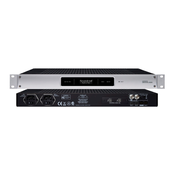
Page 23: Rear Panel
Rear Panel This section describes the function of all switches and connectors on the Realtime Rack front panel. PSU 1 PSU 2 100V-240V 100V-240V SOUNDCRAFT 0.30A 50-60 Hz REALTIME RACK 0.30A 50-60 Hz DESIGNED IN CALIFORN (1) AC Power Inputs Connect standard detachable IEC power cables to the dual redundant internal power sup- ply units here. -
Page 24: Thunderbolt Ports
Rear Panel (continued) PORT 1 ( ) PORT 2 ( ) UNIVERSAL AUDIO, INC. DE IN CHINA 1394b 1 1394b 2 MADI IN (3) Thunderbolt Ports Connect a Thunderbolt cable (not included) between one of these ports and the Thunder- bolt port on the Mac host computer that is running the Realtime Rack software applica- tion. -
Page 25: Word Clock Termination Switch
(6) Word Clock Termination Switch This pushbutton switch provides internal 75-ohm word clock input signal termination when required. Word clock termination is active when the switch is engaged (depressed). Realtime Rack’s termination switch should only be engaged when Realtime Rack is set to sync to external word clock and it is the last device at the receiving end of a word clock cable. -
Page 26: Standalone Behavior
Standalone Behavior Realtime Rack supports limited standalone functionality in the event that the Thunder- bolt connection to the Mac host computer is lost, or if the Realtime Rack hardware unit is power cycled and no host computer is found upon re-powering the hardware. Thunderbolt connection lost –... -
Page 27: Chapter 3: System Setup
Chapter 3: System Setup System Setup Overview Realtime Rack system setup requires these primary procedures, all of which are detailed in this chapter: • System connections (device wiring) • Realtime Rack software installation • Hardware device registration and UAD plug-in authorization •... -
Page 28: System Connections
System Connections Interconnect the Realtime Rack hardware unit, the Realtime Rack software host com- puter, and the Soundcraft Vi console using the illustrations in this section. About Realtime Rack system connections • Connect Realtime Rack to the host computer via Thunderbolt only (do not connect to the host computer via 1394b ports). -
Page 29: Single Unit Wiring
Wiring Rear Panel Realtime Rack software HiQnet™ Ethernet Port MADI Optical SC PORT 1 ( ) PORT 2 ( ) UNIVERSAL AUDIO, INC. MADI IN Realtime Rack Unit Thunderbolt Ethernet Adapter Thunderbolt Ethernet MADI Optical SC System interconnections for a single Realtime Rack setup... -
Page 30: Multi-Unit Wiring
• One Cat 5 Ethernet cable between host Mac and Vi console for snapshot control • One Apple Thunderbolt to Gigabit Ethernet Adapter (Apple part number MD463ZM/A) for Ethernet PORT 1 ( ) PORT 2 ( ) UNIVERSAL AUDIO, INC. MADI IN Realtime Rack Unit Thunderbolt Ethernet... -
Page 31: Software Installation
Software Installation Complete Realtime Rack software installation consists of two main steps: • Realtime Rack software installation • Device registration and UAD plug-in authorization Preparation Close all open files and applications before starting the software installation procedure (the installer requires a restart after installation). If you are updating to a newer version of Realtime Rack software or installing additional Realtime Rack hardware units, it is not necessary to remove the previous Realtime Rack software or hardware from the system before software installation. -
Page 32: Device Registration & Authorization
Device Registration & Authorization Important: The following steps require an Internet connection to the host comput- er. To authorize a system that is not connected to the Internet, see Offline Authori- zation on page Before proceeding, confirm that the Realtime Rack software is has already been installed and the Realtime Rack hardware is powered and connected to the computer via Thunder- bolt (the hardware and software systems must be communicating properly). - Page 33 5. After registration is complete, click the blue “Download Authorizations»” button at the bottom of final registration page to download the authorization file (if it does not download automatically). The auth.uad2 file is downloaded to the default location specified by the web browser. 6.
-
Page 34: Offline Authorization
Offline Authorization To authorize a system that is not connected to the Internet, you'll need manually transfer the registration URL generated by the UAD Meter & Control Panel software into the web browser of an Internet-enabled computer. After following the web portion of the registration/authorization process and the autho- rization file is obtained on the Internet computer, you'll need to manually move the file back to the offline computer to complete the process. -
Page 35: Operating System Software Configuration
Operating System Software Configuration Before using Realtime Rack, specific settings must be made in the Mac OS X System Preferences>Energy Saver panel. Mac OS X System Preferences The System Preferences application can be accessed from the Apple Menu (under the Apple icon at the upper left of the OS X Menu Bar), or from the file system at: •... -
Page 36: Wake For Wi-Fi Network Access
Wake for Wi-Fi network access In the Power Adapter tab, enable the "Wake for Wi-Fi network access" option by selecting the option checkbox. Soundcraft Vi Series consoles require "Wake for Wi-Fi network access" to be enabled on Mac OS X in order to prevent losing the communication link between the Mac running Realtime Rack and the Soundcraft Vi console if/when the Mac enters Sleep mode. -
Page 37: Realtime Rack Software Configuration
Realtime Rack Software Configuration To properly communicate with the hardware, software settings within the Realtime Rack application must be configured for the Realtime Rack system. To configure the system settings: 1. Confirm that the Realtime Rack hardware is properly connected and powered. 2. -
Page 38: Chapter 4: Realtime Rack Application
Chapter 4: Realtime Rack Application Application Overview The Realtime Rack software application is the software interface for the Realtime Rack hardware. The application is used to configure the Realtime Rack hardware and control UAD Powered Plug-Ins. It can control up to four hardware units concurrently. All applica- tion operations are detailed in this chapter. -
Page 39: Global Displays
Global Displays Items that facilitate navigation and visual feedback that is crucial in performance en- vironments are always displayed in the Meter Bridge and Info Bar. Banks of channels and individual channels can be quickly navigated with the Bank Bar and Channels Bar to quickly get to a channel for editing. -
Page 40: Entering & Exiting The Application
• Single-click the Realtime Rack icon that was placed in the Mac OS X Dock during software installation, or • Double-click the Realtime Rack application that was installed to: /Applications/Universal Audio/ Full Screen Display When Realtime Rack is launched, the application expands to fill the entire screen (it cannot be re-sized). - Page 41 Realtime Rack Terms For the purpose of describing Realtime Rack operations in this chapter, the following definitions are used. Screen – All elements currently visible on the computer display. Some displayed ele- ments are common to all screens, while other elements depend on the active View and/or selected function.
-
Page 42: Navigation Overview
Navigation Overview This section provides an introduction to the various screen elements and navigational concepts. Items in this section are explained in greater detail later in this chapter. Views Overview Realtime Rack has six primary screens called Views. Each View displays related visual and control elements. -
Page 43: Global Navigation Elements
Global Navigation Elements The Main Column, Meter Bridge, Channels Bar, and Info Bar can all be used to navigate to different View screens. The location of these elements are illustrated below. Main Bank Bar Current Column (blue) Bank Meter Bridge Channels (Elements displayed in this area View... -
Page 44: View Menu
View Menu To access any View screen, click the View Menu at the top of the Main Column, and select a View from the drop menu, as shown at right. View Options The View Options are buttons used to activate various control func- tions within each View. -
Page 45: Banks
Banks A fundamental navigational concept in Realtime Rack is the Bank. A Bank is a subset of all available MADI channels. Channels contained within a Current Bank are represented by the Channel Select Buttons in the Channels Bar and the Bank Bar. -
Page 46: Bank Concept
Bank Concept Conceptual illustration of a Bank within Realtime Rack. In this example, the Current Bank is channels 4 through 11. Moving the thin blue Bank Bar changes the Current Bank channels. Meter Bridge The Meter Bridge is always displayed across the top of all screens. The Meter Bridge contains Input Meters for all MADI channels in the system. -
Page 47: Meter Bridge Navigation
Meter Bridge Navigation The Meter Bridge can be used as navigation shortcuts for the functions below: • Jump to any channel – Double-click any channel’s Input Meter in the Meter Bridge to jump directly to Channel View and select the channel. To return to Bank View: •... -
Page 48: Keyboard Focus
Keyboard Focus When elements on the screen have keyboard focus, they can be manipulated with the QWERTY keyboard. Keyboard focus in Realtime Rack is indicated by a yellow outline box around the screen elements targeted for control with the QWERTY keyboard. These highlighted items can typically be manipulated by using the up/down/left/right arrow keys and/or the Return/Enter keys. -
Page 49: Keyboard Shortcuts
Keyboard Shortcuts In addition to keyboard focus/navigation methods, Realtime Rack supports the keyboard shortcuts listed in the table below. Shortcut Name Keyboard Command Description Save Snapshot COMMAND+S Saves the current snapshot in place Save Snapshot As... COMMAND+SHIFT+S Saves the current snapshot as a new snapshot and allows renaming Hide Application COMMAND+H... -
Page 50: Global Screen Elements
Global Screen Elements The Main Column, Current Bank, Meter Bridge, Channel Bar, and Info Bar are groups of elements appear on all screens. These global elements are described in this section. Refer to the illustration below for descriptions in this section. Main Bank Bar Current... -
Page 51: View Menu
View Menu The six main Views can be accessed with the View Menu. To ac- cess any View, click the View Menu at the top of the Main Column, and select a View from the drop menu, as shown at right. View Options The View Options are buttons used to activate various control func- tions within each View. -
Page 52: Meter Bridge
Meter Bridge The Meter Bridge is always displayed across the top of all screens. The Meter Bridge contains Input Meters for all MADI channels in the system and can be used for naviga- tion within Realtime Rack. Mono Stereo Signal Channel Channel Present... -
Page 53: Channels Bar
Channels Bar The Channels Bar is used for channel navigation and to quickly select channels for editing. Refer to the illustration below for descriptions in this section. Current Bank (channels within the Bank Bar) Bank Bar (blue) Channel Select Buttons Selected Unselected Stereo... -
Page 54: Bank Bar
Selected Channel The currently selected channel within the Current Bank is highlighted by a blue Channel Select button. Functions in Channel View are always performed on the selected channel. Bank Bar The blue Bank Bar represents all channels in the Current Bank. -
Page 55: Info Bar
Info Bar The Info Bar is always displayed in all screens, providing visual information and access to options that are critical in performance environments. Refer to the illustration below for all Info Bar descriptions in this section. Active Snapshot Active Tempo (BPM) (italics=modified) Display &... -
Page 56: Operating Mode
Operating Mode Realtime Rack has two switched operating modes: EDIT and SAFE. EDIT Mode Edit mode is typically used for setup and configuration. Edit mode allows all functional- ity, no matter how potentially destructive, to be executed. Ideally, settings that can only be modified in Edit mode are used before a live perfor- mance to minimize the risk of level changes, clicks/pops, or other audio artifacts that could occur with some operations. -
Page 57: Safe Mode Constraints
Safe Mode Constraints View screen operations that cannot be executed in Safe mode are detailed in the table below. Caution: When Safe mode is active, Snapshots can still be recalled, which can potentially overwrite current plug-in assignments and cause audio artifacts during live a performance. -
Page 58: Clock Display
Soundcraft CUE Name When a Snapshot is loaded remotely from a Sound- craft Vi Console (via Ethernet), the Active Snapshot is overwritten. When this occurs, [SOUNDCRAFT CUE] is displayed, as shown at right. Caution: When a Snapshot CUE is loaded from a Soundcraft Vi Console, the Active Snapshot is overwritten, any unsaved changes are lost, and audio artifacts could occur. -
Page 59: Tempo Display
Tempo Display This area displays the tempo value of the Active Snapshot in BPM (beats per minute) and facilitates selection of a different tempo. The tempo value is used by time-based UAD plug-ins (such as delays and echos) that are set to use their Tempo Sync features. For details about how to use UAD plug-ins with this feature, see “Tempo Sync”... -
Page 60: Changing Tempo Values Via Midi
Changing tempo values via MIDI Tap tempo can be used to set a new tempo from incoming MIDI that are received via the Mac OS X operating system. This method requires any external MIDI hardware and/or MIDI software that is recognized by Audio MIDI Setup (which is Mac OS X’s MIDI routing utility application (located in /Applications/Utilities). -
Page 61: Resource Display
Resource Display UAD plug-in loads are shown in the Resource Display at the far right of the Info Bar. These three meters (DSP, PGM, and MEM) provide important visual feedback in realtime, by helping to determine which plug-ins to load if available UAD resources are limited. Program Memory Meter DSP Meter Memory Meter... -
Page 62: Dsp
UAD Plug-Ins Loads The amount of UAD resources used by UAD plug-ins vary with each individual plug-in; more complex algorithms require more resources. The amount of DSP used by each individual UAD plug-in is available in the UAD in- stance count chart. The chart can help determine which to plug-ins to assign with avail- able resources. -
Page 63: Inserts View
Inserts View Inserts View displays an overview of the current state of all inserts within all channels within the Current Bank. An insert is a single slot, within a single channel, where UAD plug-ins are instantiated. This view is where plug-ins can be very rapidly disabled, moved, removed, copied, and isolated using the Inserts Options. -
Page 64: Channel Column
Channel Column The channel column provides an overview of the plug-in state of a single channel, and all channels in the bank are displayed con- currently. All UAD plug-ins loaded in the channel are displayed here, along with an output meter for the channel. Note: The number of displayed channel columns is defined by the bank size setting in Settings View. -
Page 65: Inserts Options Overview
Output Meter – This meter displays the signal level at the output of the channel (after all plug-in processing in the channel). Inserts Options Overview The Inserts Options (in the Main Column, below the View Menu) en- able various operations to be performed on the plug-ins displayed within Inserts View. -
Page 66: Inserts Option Descriptions
Inserts View showing the modifiers that appear when the move option is latched. Swipe across channels and/or insert slots to rapidly perform the function on many inserts. Inserts Option Descriptions The functions of each Insert Option are detailed below. The descriptions and screenshots are applicable when the option button is latched (blue). -
Page 67: Power
Power The Power option deactivates an individual plug-in within a single insert slot. When deactivated, the plug- in no longer uses UAD DSP resources. Click the modi- fier to change the power state. When Power is latched, deactivated plug-ins are in- dicated by a red modifier, and active plug-ins have a green modifier. -
Page 68: Copy
Copy The Copy option is used to duplicate an individual plug-in or complete channel strip, and their active set- tings. Copy can be performed from one insert slot to another insert slot (on the same or a different channel), or from one channel to another channel, within the Current Bank. -
Page 69: Isolate
Isolate Isolate prevents a channel’s active settings from being modified when a Snapshot (a Re- altime Rack configuration file) is loaded. Isolate is typically used to prevent channel adjustments made during a live performance from being overwritten by Snapshot changes. When Isolate is latched, click any column modifier to isolate the channel. -
Page 70: Gains View
Gains View Gains View displays input/output gain level controls, and signal input/output level me- ters, for all channels within the Current Bank. Channels can also be stereo linked and unlinked in this view. Refer to the illustration below for all Gains View functions detailed in this section. Unlinked Linked Channel... -
Page 71: Gain Elements
Gain Elements Each input and output channel has its own set of gain controls and indicators. Refer to the illustration below for descriptions of the elements that follow. Unlinked Linked Channel Channel (mono) (stereo) Gain Type Value Display Display Fader Gain Fader Handle &... -
Page 72: Fader Handle
Input Faders The input faders adjust the level of the MADI signal before plug-in processing. Tip: By adjusting the input gain, different sonics can be obtained with UAD plug- in emulations that have (desirable) non-linear input distortion characteristics. Output Faders The output faders adjust the level of the MADI signal after plug-in processing. -
Page 73: Gains Options
Activating Link Stereo pairs are created by clicking the LINK button between two adjacent channels. Caution: When Link is activated, all channel and plug-in settings in the right channel are overwritten by the plug-ins and gains in the left channel. This opera- tion cannot be undone. -
Page 74: Inputs
Inputs When the Inputs option is active (when the button is blue), only the input gains are dis- played. This option enables increased resolution of the gain faders and level meters by increasing the vertical space devoted to the input channels (versus the Both option). Outputs When the Outputs option is active (when the button is blue), only the output gains are displayed. -
Page 75: Delay Groups View
Delay Groups View Delay Groups are latency compensation tools used to maintain phase alignment across multiple channels when upsampled UAD plug-ins are used in Realtime Rack. Refer to the illustration below for element descriptions in this section. Channel Active Inactive Active Column Delay Group... -
Page 76: Delay Groups Overview
Delay Groups Overview Upsampled UAD plug-ins Some UAD plug-ins are upsampled, meaning their internal sample rate is increased to achieve sonic design goals. When upsampled UAD plug-ins are loaded in Realtime Rack, additional latency delay is induced in the channel(s) using the plug-in(s). Although the delay added by each upsampled UAD plug-in is negligible (typically be- tween 0-140 samples, depending on the plug-in and sample rate), this extra delay can affect output phase coherency. -
Page 77: Delay Groups Options
Delay Groups Options The Delay Groups Options (in the Main Column, below the View Menu) change which Delay Group buttons are displayed and changes the amount of delay compensation that is available. Delay Group Button Selectors These buttons determine which Delay Group buttons are displayed in the main screen area. -
Page 78: Delay Groups Elements
Delay Compensation Exceeded If the maximum available delay compensation amount is exceeded on a channel when inserting an upsampled plug-in, a notification dialog appears. To maintain phase align- ment if this occurs, either increase the Compensation Menu value or reduce upsampled plug-ins usage on the channel. -
Page 79: Output Meter
Output Meter The Output Meter displays the MADI channel’s output level after plug-in pro- cessing but before the output fader (post plug-ins, pre-fader). The channel number and name are also displayed here. The channel name’s proximity to the Samples display facilitates confirmation that related channels are being delay compensated by the same amount. -
Page 80: Delay Groups Example
Delay Groups Example The screenshot below shows an example of a properly configured Delay Group. The TOM and OH channels are assigned to the same Delay Group (Delay Group #1 in this exam- ple), and the Samples value is identical for both channels. Note that the Bass channel is not in the Delay Group. -
Page 81: Upsampling Values Table
Upsampling Values Table The table below lists the additional latency values, in samples, produced by upsampled UAD plug-ins. Sample Rate (kHz) Upsampled UAD Plug-In 44.1 88.2 Precision Limiter API 550 A API Vision Console Channel Strip Neve 33609 Fairchild Tube Limiter Collection FATSO Jr./Sr. -
Page 82: Channel View
Channel View Channel View displays the plug-ins, channel strips, I/O gains, and other settings within a single channel. Channel View is used to assign and edit UAD plug-ins and manage plug- ins preset settings. The channel that is currently being viewed can be navigated with the Channel Bar. The currently selected channel is highlighted in blue in the Channel Bar. -
Page 83: Two View Modes: Single View & Channel Strip View
Two View Modes: Single View & Channel Strip View Channel View has two fundamental modes of operation: Single view mode and Channel Strip view mode. Single mode facilitates the viewing, editing, and management of in- dividual plug-ins within a channel, while Channel Strip mode facilitates the concurrent viewing, editing, and management of all serially stacked plug-ins within a channel. -
Page 84: Channel View Options
PLUG-IN Selected Channel View Options Channel (blue) In Channel View, the View Options in the Main Column is identical in both Single and Channel Strip view modes. The options in Channel Channel View are the Channel Name button, the Insert buttons, and the Chan- Name nel Strip button. -
Page 85: Insert Buttons
Insert Buttons The Insert Buttons are located in the Main Column. Each Insert Button represents one of the eight insert slots for available for UAD plug-in processing within a single channel. Populated inserts contain the plug-in name and empty inserts con- tain the plus “+”... -
Page 86: Channel Signal Flow
Channel Signal Flow Audio signals in a channel flow through the inserts serially from top to bottom. Therefore, if more than one plug-in is inserted in a channel, the location of a plug-in within the inserts can impact the sound of the channel. Insert Reordering Inserts can be reordered to change the location of a plug- in within the channel signal flow. -
Page 87: Channel Strip Button
Note: The plus “+” symbol on all Insert buttons is hidden in SAFE mode. Channel Strip Button The Channel Strip button is used to enter Channel Strip view. Chan- nel Strip view combines all plug-ins in a channel into a single view for convenient editing and settings management. -
Page 88: Plug-In Tab
PLUG-IN Tab The PLUG-IN Tab is where the UAD plug-in interface is displayed and plug-in parameters are edited. In Single view, the PLUG-IN Tab displays the plug-in interface of the cur- rently selected Insert Button in the Main Column. In Channel Strip view, the interfaces of all plug-in in the channel are displayed concurrently. -
Page 89: Channel Strip View
Channel Strip View If Channel Strip view is active, the interfaces all inserted plug-ins in the channel are dis- played in the PLUG-INS tab concurrently. In Channel Strip view, the Tab name is PLUG- INS (plural) to reflect that multiple plug-in interfaces are displayed in Channel Strip view concurrently. -
Page 90: Status Bar
Status Bar The Status Bar is a horizontal strip below the plug-in interface that appears when there is an exception to the usual operational state of the plug-in. The status bars are described below. The Status Bar appears beneath the plug-in interface to indicate operating exceptions •... -
Page 91: Power Button
Power Button The Power button deactivates the selected plug-in and reduces UAD resource loads. When a plug-in is deactivated with this button, the button is red and POWERED OFF appears in the Status Bar under the plug-in interface. The Power button is located between the Tabs and the ZOOM slider in Channel View when the PLUG-IN Tab is active. -
Page 92: Presets Tab
PRESETS Tab The PRESETS tab is where UAD plug-in settings are managed after a plug-in is assigned to an Insert. Preset management tasks are performed on the currently selected Insert. The PRESETS tab displays 3 columns with the currently selected plug-in’s presets, sub- folders (if applicable), and the FILE menu for creating user-defined presets and folders. -
Page 93: Channel Strip Defined
Factory Presets Factory presets are plug-in settings created by the plug-in developers for typical use case scenarios. All UAD plug-ins developed by Universal Audio include a batch of factory presets. They can be used as-is, or modified as desired. All factory presets are read-only; they cannot be overwritten, renamed, deleted, or moved. -
Page 94: Presets Tab Columns
All Channel Strip files are stored at the following location within the Mac OS X file sys- tem: • Macintosh HD/Library/Application Support/Universal Audio/Presets/Channel Strip Channel Strip Sub-Folders The Channel Strip folder may contain a maximum of one nested sub-folder for additional channel strip organization capability. -
Page 95: Presets Column
DELETE Presents the DELETE PRESET dialog overlay so the currently selected item can be per- manently deleted. This operation cannot be undone. MOVE Presents the MOVE dialog overlay so the currently selected item can be moved to another location within the plug-in’s preset folder. PRESETS Column When the PRESETS tab is selected, the PRESETS column is visible and all items... -
Page 96: Assign Tab
ASSIGN Tab The ASSIGN tab is used to assign (load) plug-ins into empty inserts and reassign (re- place) existing plug-ins that are already assigned in a channel insert. Actions in the AS- SIGN tab are performed on the currently selected insert. Note: The ASSIGN tab is unavailable in Channel Strip view. -
Page 97: Plug-In Categories
Plug-In Categories Available plug-in categories are listed in the table below. Note: Some plug-ins are in multiple categories (when applicable). CATEGORY CONTENTS Indicates that no plug-in is assigned. If a plug-in is already assigned, NONE the button can be used to unload the plug-in. CHANNEL STRIPS Single plug-ins featuring multiple modules, such as EQ and dynamics COMPRESSORS &... -
Page 98: Reassign Insert
Reassign Insert 1. Single-click any populated insert button in any View screen to switch into Channel view and select the insert. The PLUG-IN tab is selected and the plug-in interface is displayed. 2. Single-click the ASSIGN tab. The CATEGORY button of the current plug-in is se- lected, along with the PRESET column (and SUB-FOLDER column, if any). -
Page 99: Snapshots View
“Show all filename extensions” option is checked in the OS X Finder’s Prefer- ences window. Snapshots Folder Location All Snapshot files are stored at the following location within the Mac OS X file system: • Macintosh HD/Users/[account name]/Documents/Universal Audio/Snapshots Realtime Rack Manual Chapter 4: Realtime Rack Application... -
Page 100: Snapshot Versus System Contents
Snapshot Versus System Contents The table details the information that is stored in a Snapshot file and the differences between a Snapshot and what is stored within the system. Settings Stored In Snapshots Settings Stored In System (changed when Snapshot is recalled) (persist when Snapshot is recalled) Snapshot name Clock Source setting... -
Page 101: Recalling Snapshots
Recalling Snapshots Recalling a Snapshot can cause destructive actions such as building and/or reordering of plug-in chains. Therefore, when a Snapshot is recalled, channels may be muted to avoid audio artifacts. If a Snapshot is loaded that has the same plug-in configuration as the currently loaded Snapshot, the plug-ins are not rebuilt and only parameter values are changed, enabling a (mostly) artifact-free Snapshot recall workflow. -
Page 102: File Columns
File Columns The upper middle section of the Snapshots View screen shows two columns that display the Snapshot folders and the Snapshot files contained within the folders. Similar to how plug-in and channel strip presets are managed, these folders and files are used to load and manipulate the files in various ways. -
Page 103: Snapshots Term Definitions
Snapshots Term Definitions The following terms are used in this section: Folders Column – The left column in Snapshots View containing the snapshot folders Snapshots Column – The right column in Snapshots View containing the snapshot files Slot – A three-digit prefix number automatically used by every Snapshot and Snapshot folder. -
Page 104: Folders Column
Folders Column The Folders column displays a list of user-defined folders that contain the user-defined Snapshots. If no folders exist (for example, if no Snapshots have ever been saved), new folders can be created with the SAVE AS option button. To learn more about creating new snapshots and folders, see “Snapshots Options”... -
Page 105: Snapshots Column
Snapshots Column The Snapshots column displays a list of user-defined Snapshot files. If no Snapshots ex- ist (for example, if no Snapshots have ever been saved), new Snapshots can be created with the NEW or SAVE AS option buttons. To learn more about creating new snapshots and folders, see “Snapshots Options”... -
Page 106: Midi Bank & Program Change Recall
MIDI Bank & Program Change Recall Snapshots can be loaded using MIDI Bank/Program change commands. The three-digit slot prefixes in the Snapshot and Snapshot folder names correspond to received MIDI bank and program numbers that will select the folders and recall the Snapshots. Snapshot folder slot numbers –... -
Page 107: Save As Button
Save As Button Saves the currently loaded Snapshot as a new Snapshot file with a new name and the new Snapshot becomes the currently loaded Snapshot. To save the Snapshot as a different file: Navigate to Snapshots View. 2. Click the SAVE AS button. The SAVE SNAPSHOT AS dialog overlay appears. The name field is highlighted, and the currently selected folder is used as the default destination in the FOLDER drop menu. -
Page 108: Delete Button
Delete Button Deletes the currently selected folder or Snapshot. Important: When a folder is deleted, all Snapshots contained within the folder are also deleted. Caution: Delete operations permanently remove user data and cannot be undone. To delete a folder or Snapshot: Navigate to Snapshots View. -
Page 109: Move Shuffle
Exported Data Location – Startup Volume Specified • Macintosh HD/Users/[account name]/Documents/Universal Audio/Exported Snap- shots/[user-defined folder name] Exported Data Location – Alternate Volume Specified • [Volume Name]/Universal Audio/Exported Snapshots/[user-defined folder name] To export all Snapshots: Navigate to Snapshots View. 2. Click the EXPORT ALL button in the Main Column. The EXPORT ALL SNAP- SHOTS dialog overlay appears. -
Page 110: Import All
If the same destinations exist, options are provided to Append, Replace, or Cancel the import operation. Imported Data Location Imported data uses the same location used by Snapshots that aren’t imported: • Macintosh HD/Users/[account name]/Documents/Universal Audio/Exported Snap- shots/[user-defined folder name] To import all Snapshots: Navigate to Snapshots View. -
Page 111: Recall Panel
Recall Panel The Recall Panel displays the Active Snapshot and the Snapshot that is primed and ready to be loaded. It also contains the Recall but- ton to load the primed Snapshot, and navigation buttons for priming Snapshots. Active Snapshot Display The Active (currently loaded) Snapshot is displayed in the blue CUR- RENT panel along with its MIDI Program Change slot number prefix. -
Page 112: Universe View
Universe View The Universe view displays a high-level overview of assigned plug-ins in the currently loaded snapshot while in Snapshot View. Universe view provides a simple way of knowing that a plug-in has been loaded and if the plug-in is active, powered off, and/or disabled. Tip: For a more detailed view of plug-in states, use Inserts View. -
Page 113: Settings View
Settings View Settings view allows the user to define various preferences, settings, and behaviors that affect the hardware and operation of Realtime Rack. Most of the settings made in the Settings view are global to the system and don’t get stored with a Realtime Rack snapshot file. -
Page 114: Hardware Tab
Hardware Tab Each setting in the Hardware tab is de- scribed below. Sample Rate Menu Sets the sample rate of the Realtime Rack system. To change the sample rate, click the SAMPLE RATE drop menu and choose a new value from the menu. Realtime Rack supports the following sample rates (in kHz): 44.1, 48, 88.2, and 96. -
Page 115: Device Buttons
Device Buttons Buttons displayed in this area depend on the number of Real- time Rack units that are connected. The screenshot shows a two unit system. Identify Unit Buttons The Identify Unit buttons (shown as “MADI 1-16” and MADI 17-32” in the screenshot at right) display which MADI channels are being processed by the Realtime rack unit(s). -
Page 116: Column Location Menu
Column Location Menu Sets the location of the Main Column in all screens containing the column. To change the Main Column location, click the COLUMN LOCATION drop menu and choose a new value from the menu. Info Location Menu Sets the location of the Info Bar in all screens. To change the Info Bar location, click the INFO LOCATION drop menu and choose a new value from the menu. -
Page 117: Midi Device Menu
MIDI Device Menu Sets the MIDI device to be used as the source for MIDI control. To set the device, click the MIDI DEVICE drop menu and choose a new device from the menu. Note: Only devices configured in Audio MIDI Setup.app are available for selection in this menu. -
Page 118: Plug-Ins Tab
Plug-Ins Tab The plug-ins tab contains various plug-in management and behavior utilities. All currently installed plug-ins are displayed, with one plug-in in each row. Use the verti- cal scroll bars to view the plug-ins that are not visible. The PLUG-INS tab in Settings View Hide Button Prevents the plug-in from being visible in the ASSIGN tab in Channel View. -
Page 119: Status Column
Status Column The authorization status and/or demo state of the plug-in is displayed. The info shown here mirrors the status shown in the Plug-Ins panel within the UAD Meter & Control Panel application. Tip: To start a plug-in demo, use the Plug-Ins panel within the UAD Meter &... -
Page 120: Soundcraft Snapshot Recall
Soundcraft Snapshot Recall When Snapshots are being recalled from a Soundcraft Vi Console, the majority of the features on the Snapshots page are not used. Instead, all Snapshot data is stored and recalled from the Soundcraft Vi Console. Complete workflows within Vi Console systems is detailed in Soundcraft’s documentation, but a general outline is provided below. -
Page 121: Chapter 5: Uad Meter & Control Panel
• Single-click the UAD Meter & Control Panel icon that was placed in the Mac OS X Dock during installation, or • Double-click the UAD Meter & Control Panel application that was installed to: /Applications/Universal Audio/ Realtime Rack Manual Chapter 5: UAD Meter & Control Panel... -
Page 122: Using The Uad Meter
Using the UAD Meter The UAD Meter & Control Panel can be launched or quit at any time. It does not need to be open or active to use the Realtime Rack application or UAD Powered Plug-Ins; it is completely independent. You can move the UAD Meter to a convenient location on your screen by dragging its window title bar. -
Page 123: Title Bar
Normal – In normal mode, the window can be covered by windows of the foreground ap- plication. Always On Top – When in Always on top mode, the Meter window always “floats” on top of other windows, even when other applications are in the foreground, so you can always see the meter and access the Disable Current button. -
Page 124: Program
Program This resource shows how much UAD-2 program memory is in use. Program memory is an on-chip memory that is specific to the UAD-2 DSP processor(s) and is used for certain UAD plug-in resources. Each unique UAD-2 plug-in uses a bit of program memory. If many different UAD-2 plug-ins are loaded simultaneously, it is possible for this resource to run out before DSP overload occurs. -
Page 125: Uad Control Panels
Note: Some controls and/or displays in the UAD Control Panels do not apply with Realtime Rack and can be ignored. They are used with Universal Audio UAD-2 devices, which also use the UAD Meter & Control Panel application. All exceptions are noted. -
Page 126: Check For Updates
Check for Updates This button checks our web server to find out if a more recent version of the Realtime Rack software is available than is currently installed. We recommend running the lat- est version of the Realtime Rack software for maximum stability and the latest features, such as new plug-ins. -
Page 127: Device Status
Device Status For each installed device, a small picture of the hardware and its status is displayed. When the device displays Status: OK the hardware is operating properly. The total num- ber of UAD plug-ins loaded on each device is also displayed here. Device Enabled Individual UAD devices can be disabled using the Device Enabled button. -
Page 128: Plug-Ins Panel
Plug-Ins Panel The Plug-Ins panel displays the current authorization status of all UAD plug-ins. This is also where you can activate Demo Mode for individual UAD plug-in (see). Use the scroll- bar to view plug-ins that may not be visible in the list. Tip: Some of the functionality of the Plug-Ins panel is duplicated/available in the Settings page within the Realtime Rack software application. -
Page 129: Status Column
Status Column The Status column reflects the current state of each UAD plug-in. After the authorization file is loaded, the status will show one of the following: Authorized for devices When the plug-in is fully licensed and authorized to run on all devices in the system, “Authorized for all devices”... -
Page 130: Configuration Panel
Configuration Panel The Configuration Panel is where most of the global UAD settings and preferences are specified for all UAD devices. The Configuration panel UAD-2 DSP Settings DSP Load Limiting Overview The UAD DSP can be limited so the load cannot exceed 100%, thereby increasing over- all system stability in high load situations. -
Page 131: Limit Dsp Load
Note: When Limit DSP Load is enabled and the DSP load limit is exceeded when instantiating a new UAD plug-in, an overload message will appear and the plug- in status bar will display “DISABLED.” Even though its interface will load in this state, the plug-in will not process audio. -
Page 132: Use Host Mode
Circular (jump) – In Circular mode, the software knobs behave similar to physical rotary knobs. Values are changed by clicking on the knob then rotating in a circular direction. When the edge of the knob is clicked, the parameter value jumps to the mouse position. Relative Circular (grab) –... -
Page 133: Help & Support Panel
Table of Contents, Index, or PDF search. View Documentation is the only button that doesn’t link to the internet. Instead, clicking this button opens the Documentation folder containing all the PDF user manuals at /Ap- plications/Universal Audio (see “Documentation Overview” on page 18). -
Page 134: Chapter 6: Using Uad Powered Plug-Ins
Chapter 6: Using UAD Powered Plug-Ins The UAD Plug-In Window A typical UAD plug-in window is shown below. The graphical user interface (GUI) typi- cally contains several control parameters for modifying the behavior of the plug-in, and display elements such as meters, for visual feedback. Typical UAD plug-in window Status Bar Under certain conditions, information about the current operating state of individual... -
Page 135: Adjusting Parameters
The UAD plug-in status bar (at bottom) Adjusting Parameters The parameter settings within each UAD Powered Plug-In can be adjusted to achieve a desired effect. Parameter values are easily modified by dragging sliders, rotating knobs, clicking switches and buttons, or by selecting values in a drop-menu. The functions of all parameters are detailed in the UAD Plug-Ins Manual. -
Page 136: Keyboard Control
Keyboard Control If you control-click a control it selects that control for keyboard control. This is useful for when you’re in circular mode, and you want to fine-adjust a control. Normally, clicking on a control in this mode makes the value jump to where you clicked. Control-clicking will select the control so that you can use the keyboard to adjust it, without making its value jump first. -
Page 137: Dsp Loading Information
DSP Loading Information • Each Realtime Rack hardware unit features four on-board SHARC DSP chips for processing UAD Powered Plug-Ins. • Multi-unit Realtime Rack systems use sophisticated load balancing routines. UAD plug-ins are always allocated as efficiently as possible, which is not necessarily on the DSP with the lowest resource usage. -
Page 138: Tempo Sync
Tempo Sync Overview The time-based parameters of numerous UAD Powered Plug-Ins can be synchronized to the tempo of the Realtime Rack software using the Tempo Sync feature. Note: The tempo used by UAD plug-ins that are set to Tempo Sync is specified in the Settings>MIDI panel within the Realtime Rack software application. -
Page 139: Available Note Values
Available Note Values The note values that are available for selection are listed in the table below. The values are listed in musical notation as a division of measures. For example 1/4 = one quarter note, 1/1 = one whole note, 4/1 = four whole notes, and so forth. The available note values were chosen to allow syncing to tempo in odd time signatures as well the common 4/4 time signature. -
Page 140: Entering Tempo Values
Entering Tempo Values In addition to adjusting the parameter knob, the two following methods can be used for entering Tempo Sync values. Arrow Keys After clicking the parameter to select it, the arrow keys can be used to scroll through available note values. -
Page 141: Modes With Tempo Sync
Modes with Tempo Sync The UAD DM-1 and UAD DM-1L plug-ins (and DM-1 within CS-1) have a Mode menu that switches the plug-in operation between delay, chorus, and flanger mode. In these plug-ins, when the Mode is set to DualDelay and PingPong, the delay Time and modula- tion Rate parameters are simultaneously available for Tempo Sync. -
Page 142: Chapter 7: My.uaudio.com
Chapter 7: My.uaudio.com My.uaudio.com is the Universal Audio online store where Realtime Rack hardware units are registered to your account and UAD plug-in authorizations are obtained. Bundled plug-ins are redeemed at the store and optional plug-in licenses can be purchased at my.uaudio as well. -
Page 143: Coupons
Authorize Plug-Ins button in the UAD Meter & Control Panel, then double-clicking the downloaded authorization file. Video Help Universal Audio’s website contains helpful videos that explain how to register and autho- rize the product, obtain optional plug-ins, and more: • www.uaudio.com/videos Procedure This section is a detailed overview of the entire UAD authorization system. -
Page 144: Authorize Plug-Ins
Authorize Plug-Ins The entire registration/account creation/authorization process involves simply clicking the “Authorize Plug-Ins” button (page 128) in the UAD Meter & Control Panel and following the on- screen instructions. Clicking this button automatically registers the installed UAD de- vices, generates the authorization file, and downloads it to the location specified in the web browser. -
Page 145: Authorization Notes
Authorization Notes • UAD devices must be authorized to run bundled (included) plug-ins. • Without authorization, UAD plug-ins can be enabled to run for 14 days without functional limitations in a timed demo mode (see below). • Older versions of the UAD software may not include all the latest plug-ins. To ensure all UAD plug-ins are installed (and for optimum performance), we recom- mend updating to the latest software version. -
Page 146: Demo Activation
My.uaudio.com can be accessed from most pages at www.uaudio.com by clicking the link in at the upper right of a Universal Audio webpage. The direct URL for the my.uaudio. com online store is http://my.uaudio.com. Accessing the UA online store from www.uaudio.com Registration Registration at my.uaudio.com is required for all Realtime Rack users to obtain UAD de-... -
Page 147: Account
Account A my.uaudio.com account is required to use UAD Powered Plug-Ins, because UAD plug- ins must be authorized for use, and authorization can only occur after the UAD device is registered to an account. Registration also entitles you to free UA Technical Support special promotional offers (if you elect to opt-in during registration). -
Page 148: Uad Plug-In Purchase Procedure
UAD Plug-In Purchase Procedure To purchase and authorize optional UAD plug-in(s): 1. Visit the UA online store at www.uaudio.com.store.html and add the desired items to your shopping cart (you may need to login to your account first). 2. Click “View cart” or the Checkout button when ready to proceed to checkout. The payment page appears. -
Page 149: Chapter 8: Specifications
Chapter 8: Specifications SYSTEM I/O Complement Thunderbolt Dual ports (Thunderbolt 2 compatible) Word Clock One input, one output MADI Optical Ports One input, one output Supported Sample Rates (kHz) 44.1, 48, 88.2, 96 (one or two units) (48 kHz only with Soundcraft Vi console) 44.1, 48 (up to four units) Bit Depth 24 bits per sample... - Page 150 Shipping Weight (with box & accessories) 6.3 kg (14 lbs) Weight (unit only) 4.1 kg (9 lbs) Package Contents Soundcraft Realtime Rack hardware unit (2) IEC AC Power Cables (1 each, Europe & USA) Getting Started sheet Set of (4) Rack-Mount Screws Realtime Rack Manual...
-
Page 151: Chapter 9: Notices
Chapter 9: Notices Maintenance Realtime Rack does not contain a fuse or other user-replaceable parts. The unit is in- ternally calibrated at the factory and recalibration should never be required. No internal user adjustments are available. Warranty & Repair The Realtime Rack hardware warranty and repair service is provided by Soundcraft. Contact Soundcraft to obtain technical support for configuration and operation of Vi-se- ries consoles, including how to setup and operate Vi-series consoles with Realtime Rack. -
Page 152: Important Safety Information
Important Safety Information Before using this unit, be sure to carefully read the applicable items of these operating instruc- tions and the safety suggestions. Afterwards, keep them handy for future reference. Take special care to follow the warnings indicated on the unit, as well as in the operating instructions. Water and Moisture –... -
Page 153: Fcc Compliance
FCC Compliance Federal Communications Commission United States Class B Manual Statement NOTE: This equipment has been tested and found to comply with the limits for a Class B digital device pursuant to Part 15 of the FCC Rules. These limits are designed to pro- vide reasonable protection against harmful interference in a residential installation. -
Page 154: Hardware Terms And Conditions
Use of the Realtime Rack hardware is governed by the Universal Audio, Inc. Hardware Terms and Conditions, which is published at: • www.uaudio.com/hardware-terms.html Software End User License Agreement Use of the Realtime Rack software is governed by the Universal Audio, Inc. Software End User License agreement, which is published at: • www.uaudio.com/eula-ua.html Disclaimer The information contained in this manual is subject to change without notice. - Page 155 www.uaudio.com www.soundcraft.com...