
Related Manuals for PEERLESS Series 63


Summary of Contents for PEERLESS Series 63
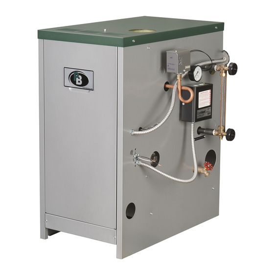
- Page 1 Series 63/64 ™ Boilers I n s t a l l a t i o n , O p e r a t i o n & M a i n t e n a n c e M a n u a l...
-
Page 2: Table Of Contents
TABLE OF CONTENTS TABLE OF CONTENTS USING THIS MANUAL 5. FUEL PIPING A. MANUAL ORGANIZATION ....1 A. INSTALLATION ..... . .16 B. -
Page 3: Using This Manual
USING THIS MANUAL USING THIS MANUAL DANGER A. INSTRUCTION MANUALS The Series 63/64™ Installation, Operation & Indicates a condition or hazard which will cause Maintenance Manual is divided into four basic sections: severe personal injury, death or major property damage. -
Page 4: Preinstallation
2. For servicing the burners provide not less than 24" A. GENERAL from the front of the boiler. Series 63/64™ boilers are supplied knocked down for field 3. The remaining clearances should be 6" from all sides. assembly or completely assembled as packaged boilers. -
Page 5: Air Combustion And Ventilation
1000 appliances other than fan assisted and for the Btu/hr (44 cm per 1000 W) of total input rating Series 63/64™ Boiler shall be determined as of all equipment. See Figure 1.2 for an follows: illustration of this arrangement. - Page 6 PREINSTALLATION 4. Outdoor Combustion Air: Outdoor combustion air is ii. Where communicating with the outdoors to be provided through one or two permanent through horizontal ducts, each opening shall openings. The minimum dimension of these air have a minimum free area of 1 in per 2000 openings is 3 inches (76 mm).
- Page 7 5. Combination Indoor and Outdoor Combustion Air: If ii. Where the free area through a louver or grille the required volume of indoor air exceeds the is not known, it shall be assumed that wooden available indoor air volume, outdoor air openings or louvers will have 25% free area and metal ducts may be used to supplement the available louvers and grilles will have 75% free area.
-
Page 8: Installation Survey
PREINSTALLATION WARNING G. PLANNING THE LAYOUT Liquefied Petroleum (LP) is heavier than air and may Prepare sketches and notes of the layout to minimize the collect or “pool” in a low area in the event of a leak possibility of interferences with new or existing from defective equipment. -
Page 9: Boiler Placement & Assembly
BOILER PLACEMENT & ASSEMBLY 2. BOILER PLACEMENT & ASSEMBLY 5. Insert the push nipples into the nipple ports of one of A. PACKAGED BOILER the split block ends. Make sure the nipples are clean and free of burrs. Use a block of wood to protect the 1. -
Page 10: Knockdown Boilers: Assembled Blocks
BOILER PLACEMENT & ASSEMBLY 11. If the sections do not draw together using the torque 5. Slide the burner tray under the cast iron block specified above, the block must be separated and the assembly and attach to the end sections using the 1/4" nipples replaced before reassembly is attempted. -
Page 11: Testing
5. Position the Inner Front Panel between the side panels and align the mounting holes on the side 1. The Series 63™ boilers employ a wrap-around style flanges with the clearance holes on the side panels. jacket while the Series 64™ boilers use an individual Attach with four #10 x 1/2"... - Page 12 BOILER PLACEMENT & ASSEMBLY 7. Attach the Draft Hood to the Flue Collector using #10 x 1/2" sheet metal screws provided. Refer to Figure 2.7. Figure 2.7: Draft Hood Attachment Figure 2.8: Label & Rating Plate Locations 8. Position the Top Jacket Panel so that the flanges 10.
-
Page 13: Venting
3. VENTING c. Do not connect the vent for this boiler into any A. CHIMNEY OR VENT vent system which operates with positive pressure. 1. Inspect the existing chimney or vent system. Make sure it is in good condition. Inspect chimney liner d. -
Page 14: Boiler Removal From Common Venting System
VENTING a. Orient the vent damper operator to facilitate a. Seal any unused openings in the common venting connection of the vent damper harness to system. knockout on right side of boiler. b. Visually inspect the venting system for proper size and horizontal pitch and determine there is no b. -
Page 15: Boiler Piping
BOILER PIPING 4. BOILER PIPING 3. If the boiler is piped in a secondary loop separate A. WATER BOILER PIPING – SINGLE from the system expansion tank, the boiler circulator BOILER should be located on the return side of the boiler pumping away from the common piping. -
Page 16: Water Boiler Piping - Multiple Boilers
BOILER PIPING 3. Pipe the steam header a minimum of 24" above the B. WATER BOILER PIPING – MULTIPLE normal water line using swing joints to attach the BOILERS risers into the steam header. Refer to the PB Heat Water Installation Survey and Hydronics Institute Residential Hydronic Heating Use Threaded Fittings for Manifold Piping Installation Design Guide for guidance on multiple boiler... -
Page 17: Steam Boiler Indirect Water Heater Piping
BOILER PIPING 6. The use of a Hartford Loop in all installations is D. STEAM BOILER INDIRECT WATER recommended to ensure reliability of the system. A HEATER PIPING check is required on the pump discharge of all pumped return systems. 1. -
Page 18: Fuel Piping
FUEL PIPING 5. FUEL PIPING Table 5.1: Gas Input & Valve Inlet A. INSTALLATION Gas Input (CFH) Gas Valve Inlet (NPT) 1. Pipe gas to the boiler in accordance with local codes. Model Nat. Gas LP Gas Nat. Gat LP Gas In the absence of local regulations refer to the National Fuel Gas Code, ANSI Z223.1/NFPA 54. - Page 19 FUEL PIPING 5. Refer to table 5.4 for minimum supply pressure for the purpose of input adjustment. Table 5.4: Minimum Supply Pressure Natural Gas Supply Pressure Model (in. Water) 63-03L 5.00 63-03 5.00 63-04L 5.00 63-04 5.35 Figure 5.3: Gas Train Manifold – 64-07 & 64-08 63-05L 5.00 Natural Gas, Standing Pilot...
-
Page 20: Controls & Trim
CONTROLS & TRIM 6. CONTROLS & TRIM 3. Pressure/Temperature Gauge: A. WATER BOILER CONTROLS & TRIM Install the pressure/temperature gauge (theraltimeter) 1. Safety Relief Valve: supplied with the boiler into the 1/2" tapping located on the right side of the boiler. Refer to Figure 6.2 for a. -
Page 21: Steam Boiler Controls & Trim
CONTROLS & TRIM B. STEAM BOILER CONTROLS & TRIM 1. Safety Valve: a. Pipe the boiler safety valve provided into the 3/4" tapping on the left side of the boiler as shown in Figure 6.4. Be sure that the relief valve is sized in accordance with local code requirements. -
Page 22: Electrical
ELECTRICAL 7. ELECTRICAL 2. Mount the blocked vent switch in the rear of the A. CONNECT SUPPLY WIRING boiler on the draft hood as shown in Figure 7.2. 1. All electrical wiring must be done in accordance with local codes. In the absence of local codes use ANSI/NFPA 70 “The National Electrical Code.”... -
Page 23: Install Control Wiring
ELECTRICAL 4. Mount the ignition module, if required (spark ignited D. WIRING DIAGRAM INDEX units only), as shown in Figure 7.4. Table 7.1: Wiring Diagram Index - Water Boilers Standing Pilot, Fig. 7.6 Fig. 7.7 Natural Gas Standing Pilot, Fig. 7.6 LP Gas Spark Ignition, Fig 7.8... - Page 24 ELECTRICAL...
- Page 25 ELECTRICAL...
- Page 26 ELECTRICAL...
- Page 27 ELECTRICAL...
- Page 28 ELECTRICAL...
- Page 29 ELECTRICAL...
- Page 30 ELECTRICAL...
- Page 31 ELECTRICAL...
- Page 32 ELECTRICAL...
- Page 33 ELECTRICAL...
-
Page 34: Boiler Operation
BOILER OPERATION 8. BOILER OPERATION normal water level is about 25-7/8" above the boiler A. SYSTEM INSPECTION foundation (about 2/3 of the gauge glass). 1. Confirm that all water, gas, and electricity are 2. Pumped Return Systems with Boiler Feed Unit - turned off. -
Page 35: Main Burner Check
BOILER OPERATION 6. Spark-Ignited Pilot Ignition Check c. Note: If the meter is not automatically corrected for temperature and pressure, the meter reading a. Turn up the Operating Temperature Control for a must be corrected to actual conditions during the call for heat. -
Page 36: Boiler Shut-Down
BOILER OPERATION WARNING 12. Close the make up water valve and open the boiler drain valve. Cleaning the boiler requires the use of very hot water 13. Drain the boiler completely. Then refill and drain and corrosive chemicals. Use care when handling to again one or two times to make sure all of the soda prevent injury. -
Page 37: To Turn Off Gas To Appliance
BOILER OPERATION FOR YOUR SAFETY READ BEFORE LIGHTING WARNING: If you do not follow these instructions exactly, a fire or explosion may result causing property damage, personal injury, or loss of life. A. This appliance has a pilot which must be lighted by If you cannot reach your gas supplier, call the fire hand. - Page 38 BOILER OPERATION FOR YOUR SAFETY READ BEFORE LIGHTING WARNING: If you do not follow these instructions exactly, a fire or explosion may result causing property damage, personal injury, or loss of life. A. This appliance has a pilot which must be lighted by If you cannot reach your gas supplier, call the fire hand.
-
Page 39: Operating Instructions
BOILER OPERATION FOR YOUR SAFETY READ BEFORE LIGHTING WARNING: If you do not follow these instructions exactly, a fire or explosion may result causing property damage, personal injury, or loss of life. A. This appliance is equipped with an ignition device Immediately call your gas supplier from a which automatically lights the pilot. - Page 40 BOILER OPERATION FOR YOUR SAFETY READ BEFORE LIGHTING WARNING: If you do not follow these instructions exactly, a fire or explosion may result causing property damage, personal injury, or loss of life. A. This appliance is equipped with an ignition device Immediately call your gas supplier from a which automatically lights the pilot.
-
Page 41: Maintenance
MAINTENANCE 9. MAINTENANCE WARNING Product Safety Information Refractory Ceramic Fiber Product This appliance contains materials made from refractory ceramic fibers (RCF). Airborne RCF fibers, when inhaled, have been classified by the International Agency for Research on Cancer (IARC), as a possible carcinogen to humans. After the RCF materials have been exposed to temperatures above 1800°F, they can change into crystalline silica, which has been classified by the IARC as carcinogenic to humans. -
Page 42: General
MAINTENANCE A. GENERAL D. MONTHLY MAINTENANCE (WITH BOILER OPERATING) 1. Disconnect this boiler from the gas supply piping during any pressure testing of the gas system. 1. Check boiler room floor drains for proper functioning. 2. Check pipes adjacent to cold walls or in unheated spaces. -
Page 43: As Required Maintenance
MAINTENANCE d. Remove the vent pipe, vent damper, top jacket 2. Inspect entire venting system for corrosion, support panels and flue collector. and joint integrity. Repair as necessary. e. Brush flueways with wire brush. 3. Check the pilot and main burner flame. See Figure f. -
Page 44: Troubleshooting
TROUBLE SHOOTING – SERVICE TIPS 10. TROUBLESHOOTING – SERVICE TIPS Problem Possible Cause Suggested Remedy Defective Thermocouple Replace Heavy Draft Blowing across Pilot Redirect Air Movement or Eliminate Plugged Pilot Orifice Replace Orifice Pilot Outage Check Manual Pilot Valve Check Main Gas Shut-Off Valve No Gas Check Manual Meter Valve Consult Gas Company... - Page 45 TROUBLE SHOOTING – SERVICE TIPS Problem Possible Cause Suggested Remedy Air Adjustment Screws Turned in Too Far Adjust Screws Out Low Gas Pressure in Manifold Adjust Main Gas Pressure Regulator (Insufficient Air Injection) or Check Line Pressure Burner Ports Partially Closed Replace Burners or Clean Ports (Rust, Dirt, Lint, etc) Burner(s) Burning with Yellow Flame...
- Page 46 TROUBLE SHOOTING – SERVICE TIPS Problem Possible Cause Suggested Remedy Clogged returns on gravity system Clean or Re-Pipe Return Line(s) Incorrect near-boiler piping causing wet steam Correct Piping per Manual to system Trap failed open, allowing steam to enter returns Replace Trap or Trap Element Use smaller Air Vent or Use Two Small Vents in {Radiator Hammer} Large radiator may be...
-
Page 47: Boiler Dimensions & Ratings
BOILER DIMENSIONS & RATINGS 11. BOILER DIMENSIONS & RATINGS Figure 11.1: Dimensions and Tapping Locations Table 11.1: Tapping Sizes & Functions Tap ID Size NPT Steam Water 1-1/4" Skim Tapping Skim Tapping 1" Tank Supply/Limit 1" Tank Return 3/4" Boiler Drain Boiler Drain 3"... - Page 48 BOILER DIMENSIONS & RATINGS Table 11.3: Series 63™ Boiler Ratings Series 63™ Water Approx. Content Shipping Standing Pilot Spark Ignition Weight, Heating Capacity³ Net I=B=R Ratings¹ AFUE³ AFUE³ Boiler Input, Model Water, Steam, Steam, Steam, Water, Water, Steam, Water, Steam,...
-
Page 49: Repair Parts
REPAIR PARTS 12. REPAIR PARTS Repair parts are available from your installer or by contacting PB Heat, LLC, 131 S. Church, Bally, PA 19503. Note: Remember to include boiler model number and serial number when ordering parts. Figure 12.1... - Page 50 REPAIR PARTS Table 12.1 Quantity Stock Quantity Stock Description Description Required Code Required Code Intermediate Section – w/out Draw Lugs – 90028 Burner Access Panel – 63-03 – 50271 Intermediate Section – w/ Draw Lugs (64) – 90029 Burner Access Panel – 63-04 –...
- Page 51 REPAIR PARTS Table 12.2 Quantity Stock Quantity Stock Description Description Required Code Required Code Gas Valve – NAT-STDG 63-03/04 Flue Collector – 63-03 – 50281 – 50581 Honeywell VR8200A-2116 Flue Collector – 63-03L – 50282 Gas Valve – NAT-STDG 63-05/06 Flue Collector –...
- Page 52 Series 63/64 ™ Boilers I n s t a l l a t i o n , O p e r a t i o n & M a i n t e n a n c e M a n u a l TO T H E I N S TA L L E R : This manual is the property of the owner and must be affixed near the boiler for future reference.