Table of Contents
Advertisement
Chapter 1. Getting
Started
Getting Started
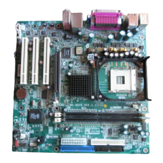
Thank you for purchasing the MS-6575 v3.X M-ATX
mainboard. The MS-6575 is based on SiS
chipsets for optimal system efficiency. Designed to fit the ad-
vanced Intel
package, MS-6575 delivers a high performance and professional
desktop platform solution.
Pentium 4/Celeron processor in the 478-pin
®
Getting Started
651 & SiS
962
®
®
1-1
Advertisement
Table of Contents

Related Manuals for HP MS-6575


Summary of Contents for HP MS-6575
-
Page 1: Chapter 1. Getting
Getting Started Chapter 1. Getting Started Getting Started Thank you for purchasing the MS-6575 v3.X M-ATX mainboard. The MS-6575 is based on SiS 651 & SiS ® ® chipsets for optimal system efficiency. Designed to fit the ad- vanced Intel Pentium 4/Celeron processor in the 478-pin ®... -
Page 2: Mainboard Specifications
MS-6575 M-ATX Mainboard Mainboard Specifications Supports Socket 478 for Intel Pentium 4/Celeron Willamette & Northwood ® processors Core Frequency from 1.5 GHz to 2.4 GHz and up Supports FSB 400/533 MHz Chipsets 651 chipset ® - High performance host interface (400/533MHz) - Page 3 Getting Started 2.88Mbytes - 1 serial port and 1 VGA port - 1 parallel port - 1 RJ-45 LAN jack (optional) - 3 audio ports in vertical - 1 IEEE 1394 pinheader and 1 IEEE 1394 port - 6 USB ports (Rear * 4/ Front * 2) Audio AC97 Codec ALC650F LAN (optional)
-
Page 4: Mainboard Layout
B: keyboard CPUFAN1 JPW1 BIOS Line-In Winbond Line-Out W83697HF B:Mic AGP Slot PCI Slot 1 8801B PCI Slot 2 8201BL JUSB1 Codec JFP1 PCI Slot 3 SYSFAN1 JFMIC1 BATT JBAT1 JCD1 JFHP1 JAUX1 JPDW1 J1394_1 JASOD1 MS-6575 v3.X M-ATX Mainboard... -
Page 5: Chapter 2. Hardware
Hardware Setup Chapter 2. Hardware Setup Hardware Setup This chapter tells you how to install the CPU, memory modules, and expansion cards, as well as how to setup the jump- ers on the mainboard. Also, it provides the instructions on con- necting the peripheral devices, such as the mouse, keyboard, etc. -
Page 6: Quick Components Guide
MS-6575 M-ATX Mainboard Quick Components Guide CPU, p.2-3 CPUFAN1, p.2-18 JPW1, p.2-9 DDR DIMMs, p.2-7 IDE2, p.2-17 FDD1, p.2-16 Back Panel I/O, p.2-10 IDE1, p.2-17 CONN1, p.2-9 JUSB1, p.2-20 JFP1, p.2-19 JFMIC1, p.2-23 J1394_1, p.2-21 JAUX1, p.2-22 JPDW1, p.2-26 JCD1, p.2-22 SYSFAN1, p.2-18... -
Page 7: Central Processing Unit (Cpu)
Hardware Setup Central Processing Unit: CPU The mainboard supports Intel Pentium 4/Celeron processor in the 478 ® ® pin package. The mainboard uses a CPU socket called PGA478 for easy CPU installation. When you are installing the CPU, make sure the CPU has a heat sink and a cooling fan attached on the top to prevent overheating. -
Page 8: Cpu Installation Procedures For Socket 478
MS-6575 M-ATX Mainboard CPU Installation Procedures for Socket 478 Please turn off the power and Open Lever unplug the power cord before installing the CPU. Sliding 90 degree Plate Pull the lever sideways away from the socket. Make sure to raise the lever up to a 90- degree angle. -
Page 9: Installing The Cpu Fan
Hardware Setup Installing the CPU Fan As processor technology pushes to faster speeds and higher performance, thermal management becomes increasingly important. To dissipate heat, you need to attach the CPU cooling fan and heatsink on top of the CPU. Follow the instructions below to install the Heatsink/Fan: Locate the CPU and its retention Position the heatsink onto the reten-... - Page 10 MS-6575 M-ATX Mainboard C o nnec t t h e f a n p o w e r c a b le f r o m t h e m o unt e d f a n t o t h e 3- p i n f a n p o w e r c o nnec t o r on t h e boa r d .
-
Page 11: Introduction To Ddr Sdram
Hardware Setup Memory The mainboard provides 2 slots for 184-pin DDR SDRAM DIMM (Double In-Line Memory Module) modules and supports the memory size up to 2GB. You can install PC2700/DDR333 or PC2100/DDR266 modules on the DDR DIMM slots (DDR 1~2). DDR DIMM Slots (DDR 1~2) Introduction to DDR SDRAM... -
Page 12: Dimm Module Combination
MS-6575 M-ATX Mainboard DIMM Module Combination Install at least one DIMM module on the slots. Memory modules can be installed on the slots in any order. You can install either single- or double- sided modules to meet your own needs. -
Page 13: Power Supply
Hardware Setup Power Supply The mainboard supports ATX power supply for the power system. Be- fore inserting the power supply connector, always make sure that all compo- nents are installed properly to ensure that no damage will be caused. ATX 20-Pin Power Connector: CONN1 This connector allows you to connect to an ATX power supply. -
Page 14: Back Panel
MS-6575 M-ATX Mainboard Back Panel The back panel provides the following connectors: Mouse IEEE1394 Parallel L-in L-out Keyboard COM A IEEE 1394 Port The 6-pin IEEE 1394 port is used to connect 1394-compatible external devices via 6-pin to 6-pin or 6-pin to 4-pin 1394 cables. -
Page 15: Mouse Connector
Hardware Setup Mouse Connector The mainboard provides a standard PS/2 mouse mini DIN connector ® for attaching a PS/2 mouse. You can plug a PS/2 mouse directly into this ® ® connector. The connector location and pin assignments are as follows: Pin Definition SIGNAL DESCRIPTION... -
Page 16: Lan Jack (Optional)
MS-6575 M-ATX Mainboard RJ-45 LAN Jack (Optional) The mainboard provides a RJ-45 connector that allows your computer to be connected to a network environment. Signal Description Activity Transmit differential pair Transmit differential pair Indicators Receive differential pair Not used Not used... -
Page 17: Serial Port Connector
Hardware Setup Serial Port Connector The mainboard offers one 9-pin male DIN connector as the serial port. It is 16550A high speed communication port that sends/receives 16 bytes FIFOs. You can attach a serial mouse or other serial device directly to it. Pin Definition SIGNAL DESCRIPTION... -
Page 18: Parallel Port Connector: Lpt1
MS-6575 M-ATX Mainboard Parallel Port Connector: LPT1 The mainboard provides a 25-pin female centronic connector as LPT. A parallel port is a standard printer port that supports Enhanced Parallel Port (EPP) and Extended Capabilities Parallel Port (ECP) mode. Pin Definition... -
Page 19: Audio Port Connectors
Hardware Setup Audio Port Connectors Line Out is a connector for Speakers or Headphones. Line In is used for external CD player, Tape player, or other audio devices. Mic is a connec- tor for microphones. Line In 1/8” Stereo Audio Connectors Line Out 2-15... -
Page 20: Floppy Disk Drive Connector: Fdd1
MS-6575 M-ATX Mainboard Connectors The mainboard provides connectors to connect to FDD, IDE HDD, case, modem, LAN, USB Ports, IR module and CPU/System/Power Supply FAN. Floppy Disk Drive Connector: FDD1 The mainboard provides a standard floppy disk drive connector that supports 360K, 720K, 1.2M, 1.44M and 2.88M floppy disk types. -
Page 21: Hard Disk Connectors: Ide1 & Ide2
Hardware Setup Hard Disk Connectors: IDE1 & IDE2 The mainboard has a 32-bit Enhanced PCI IDE and Ultra DMA 33/66/ 100 controller that provides PIO mode 0~4, Bus Master, and Ultra DMA 33/ 66/100 function. You can connect up to four hard disk drives, CD-ROM and other IDE devices. -
Page 22: Fan Power Connectors: Cpufan1/Sysfan1
MS-6575 M-ATX Mainboard Fan Power Connectors: CPUFAN1/SYSFAN1 The CPUFAN1 (processor fan) and SYSFAN1 (system fan) support sys- tem cooling fan with +12V. It supports three-pin head connector. When con- necting the wire to the connectors, always take note that the red wire is the positive and should be connected to the +12V, the black wire is Ground and should be connected to GND. -
Page 23: Front Panel Connector: Jfp1
Hardware Setup Front Panel Connector: JFP1 The mainboard provides one front panel connector for establishing elec- trical connection to the front panel switches and LEDs. JFP1 JFP1 Pin Definition SIGNAL HD_LED_P PWR_LED_P HD_LED_N PWR_LED_N RST_SW_N PWRBTN# RST_SW_P KEY (NO PIN) 2-19... -
Page 24: Front Usb Connector: Jusb1
MS-6575 M-ATX Mainboard Front USB Connector: JUSB1 The mainboard provides one front Universal Serial Bus connector for you to connect to USB devices. JUSB1 Pin Definition Signal Signal V_FP_USBPWR0 V_FP_USBPWR0 USB_FP_P0- USB_FP_P1- USB_FP_P0+ USB_FP_P1+ KEY (NO PIN) USB_FP_OC0 2-20... - Page 25 Hardware Setup IEEE 1394 Connectors: J1394_1 The mainboard provides one 1394 pin header that allows you to con- nect optional IEEE 1394 ports. J1394_1 Pin Definition Signal Signal TPA+ TPA- TPB+ TPB- +12V +12V (No pin) 2-21...
-
Page 26: Cd-In Connector: Jcd1
MS-6575 M-ATX Mainboard CD-In Connector: JCD1 The connector is for CD-ROM audio connector. Front Line-In Connector: JAUX1 The connector is for DVD add-on card with Line-in connector. JAUX1 JCD1 JCD1 Pin Definition JAUX1 Pin Definition Signal Signal CD-L Audio Aux-L Audio... - Page 27 Hardware Setup Front MIC IN Header: JFMIC1 This connector is used to connect the front panel microphone if available. Front HeadPhone Header: JFHP1 This connector is used to connect the front headphone if available. JFMIC1 JFHP1 JFHP1 Pin Definition JFMIC1 Pin Definition Signal HP_R Signal Signal...
- Page 28 MS-6575 M-ATX Mainboard Amplified Speaker Out Daughter Card Header: JASOD1 This connector provides speaker output with amplifier via external bracket. JASOD1 Pin Definition Signal +12V Speak Out-R Signal Analog Ground Speak Out-L Signal 2-24...
-
Page 29: Clear Cmos Jumper: Jbat1
Hardware Setup Jumpers The motherboard provides the following jumpers for you to set the computer’s function. This section will explain how to change your motherboard’s function through the use of jumpers. Clear CMOS Jumper: JBAT1 There is a CMOS RAM on board that has a power supply from external battery to keep the data of system configuration. -
Page 30: Clear Bios Password Jumper: Jpwd1
MS-6575 M-ATX Mainboard Clear BIOS Password Jumper: JPWD1 The jumper is used to clear the BIOS password. To clear the password, open the jumper and restart your computer. JPWD1 Normal Clear 2-26... -
Page 31: Pci (Peripheral Component Interconnect) Slots
Hardware Setup Slots The motherboard provides one AGP slot and three 32-bit PCI bus slots. AGP Slot PCI Slots AGP (Accelerated Graphics Port) Slot The AGP slot allows you to insert the AGP graphics card. AGP is an interface specification designed for the throughput demands of 3D graphics. It introduces a 66MHz, 32-bit channel for the graphics controller to directly access main memory and provides two levels of throughputs: 2x (533Mbps) and 4x (1.07Gbps). -
Page 32: Pci Interrupt Request Routing
MS-6575 M-ATX Mainboard PCI Interrupt Request Routing The IRQ, abbreviation of interrupt request line and pronounced I-R-Q, are hardware lines over which devices can send interrupt signals to the microprocessor. The PCI IRQ pins are typically connected to the PCI bus INT...