
Related Manuals for Sony DSR-DU1


Summary of Contents for Sony DSR-DU1
- Page 1 3-620-597-11 (1) Video Disk Unit Operating Instructions Before operating the unit, please read this manual thoroughly and retain it for future reference. DSR-DU1 © 2002 Sony Corporation...
- Page 2 For customers in the USA WARNING This equipment has been tested and found to comply with the limits for a Class A digital device, pursuant to To prevent fire or shock hazard, do not Part 15 of the FCC Rules. These limits are designed to expose the unit to rain or moisture.
-
Page 3: Table Of Contents
Overview ..............4 Features of This Unit .......... 4 Supported Camcorders ........4 Using the CD-ROM Manual ......5 Getting the Best Performance from the DSR-DU1 .................. 6 Places to Avoid ........... 6 Operation ............6 Care of the Unit ..........6 Names and Functions of Parts ...... -
Page 4: Overview
• For monitoring purposes, the interval recording Overview function provides long-term recording. Supported Camcorders Features of This Unit The DSR-DU1 can be used connected to any of the The DSR-DU1 Video Disk Unit incorporates a 2.5-inch, following camcorders. 40 gigabyte hard disk. • DSR-370/370P Connected to a Sony digital camcorder through the •... -
Page 5: Using The Cd-Rom Manual
The supplied CD-ROM includes operation manuals for failure, contact a Sony service representative. the DSR-DU1 series of camera control unit (English, French, German, Italian Spanish and Chinese versions). • MMX and Pentium are registered trademarks of Intel Corporation or its subsidiaries in the United States and other countries. -
Page 6: Getting The Best Performance From The Dsr-Du1
• Avoid getting volatile liquids such as insecticides on the unit, or leaving it in contact with rubber or plastic products for a long time, as this can cause the material of the unit to deteriorate, or remove the finish. Getting the Best Performance from the DSR-DU1... -
Page 7: Names And Functions Of Parts
Jog dial a DC IN connector Press this to enter a cue point. You can enter cue Connect the power supply to the DSR-DU1 from an points either during recording or playback, and a AC adaptor or similar. maximum of 400 cue points can be set. -
Page 8: Remote Controller
(see page 22). Press once more to return to the DSR-DU1 status display (see next item). s i.LINK cable This cable is supplied with the DSR-DU1, and has j POWER switch a 4-pin connector at each end. Connect the L- This powers the DSR-DU1 on or off. - Page 9 Display Type Indication Meaning Display Type Indication Meaning area area PARA Coupled to Remaining BATT Adequate battery camcorder main [xxxx] capacity battery When A is “PC- Blank capacity REMOTE” BATT DUPLICATE DUPULICATE [xxx mode BATT Timecode Timecode reader type timecode BATT Timecode generator timecode...
-
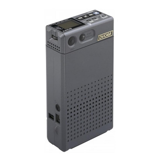
Page 10: Dsr-Du1 Video Disk Unit (Removed From Supplied Case)
Fit the optional NP-F960/F750 battery pack. This c Backup battery box acts as the main power supply for the DSR-DU1. Open the lid, and insert the supplied lithium battery To remove the battery pack, hold down the PUSH (CR2032). -
Page 11: Ca-Du1 Camera Adaptor (Option)
Connect the power supply from an AC adaptor or similar. b REMOTE connector Connect the remote controller supplied with the DSR-DU1. c DV IN/OUT connector (4-pin) Connect to the camcorder using the i.LINK cable (4-pin – 6-pin) supplied with the camera adaptor. -
Page 12: Example System Configurations
With the i.LINK cable (4-pin - 4-pin) supplied with • Install a battery pack (NP-F960/F750). the DSR-DU1, connect together the DV IN/OUT • Connect an AC adaptor to the DSR-DU1 DC IN connectors of the DSR-DU1 and the camcorder. connector. -
Page 13: Connecting To A Camcorder Through The Ca-Du1 Camera Adaptor
6-pin connector to the DV Note OUT connector of the camcorder, and the 4-pin Whe the DSR-DU1 is connected, do not use the DC connector to the DV IN/OUT connector of the IN connector of the camcorder. This connector does camera adaptor. -
Page 14: Use As A Source Feeder Supporting The Sbp2 Protocol
DSR-DU1 Video Disk Unit 4-pin i.LINK cable • When using the DSR-DU1 as a source feeder, in menu Notes page 1 set MODE to STD, and in menu page 3 set • When using the SBP2 protocol, in menu page 1, set PARAREC to OFF. -
Page 15: Inserting And Replacing The Lithium Battery
• Use only CR2032 Lithium Batteries. Other types of lithium batteries may come loose when this camcorder is moved. If you have difficulty finding CR2032 Lithium Batteries, contact your Sony dealer. Turn the POWER switch on. Press the catch at the top of the battery cover and open the cover. -
Page 16: Operation
The L-series InfoLithium battery are identified by a When using an optional InfoLithium* battery (L-series) mark. as the power supply for the DSR-DU1, use the following method to charge the battery before use. Note * InfoLithium is a trademark of Sony Corporation. -
Page 17: Menu Settings
Use the following procedure. Menu Settings Main battery box Before using the DSR-DU1 for the first time after purchase, the following menu settings are necessary. • SYSTEM (525/625 selection) (see page 23) • DATE PRESET (date and time setting) (see page 23) Check the other individual items, and if required, change their settings. - Page 18 CTL set to ON, you can record on the DSR-DU1 refer to the section of the camcorder operating coupled to the camcorder tape operations. To do instructions describing the settings in the this, on the DSR-DU1 set the menu item advanced menu.)
-
Page 19: Recording The Image From The Camcorder To Hard Disk
Use the following procedure. (Read this in conjunction with the operating instructions for the DSR-370/370P/ Note 570WS/570WSP.) If the DSR-DU1 and the connected camcorder are both powered on, there may be no i.LINK input from the Power on the DSR-DU1. camcorder to the DSR-DU1, depending on the camcorder. -
Page 20: Keeping A Recording Of The Last Few Seconds Of Material Before Pressing The Recording Button - Cache Recording
Recording) Playback This function is convenient for recording observations You can check the playback video from the DSR-DU1 in of very slow events, such as the opening of a flower. Use the camcorder viewfinder or LCD monitor. the following procedure. -
Page 21: Setting Cue Points
Press the M button for the same effect in the opposite direction. Using the above jump and search operations, you can rapidly start playback on the DSR-DU1 from any desired point. Notes • For the i.LINK interface to switch from output to input takes several seconds. -
Page 22: Menus
Page 3 (When MODE is set to STD or INT only) Menus Item Setting and values (factory default settings shown by an asterisk) Most of the DSR-DU1 settings are carried out in DELETE Delete the most recently recorded clip. the menus. LAST A confirmation message appears. -
Page 23: Making Menu Settings
“ON.” In this press to confirm. Next, turn the jog dial to change case, the ., B, and > buttons on the DSR-DU1 are disabled. the value and press to confirm. - Page 24 The LCD monitor shows the following. The setting is displayed here. When you selected “OK,” a message “TURN OFF/ ON POWER!!” appears. Power off the DSR-DU1, then power it on again. To make a setting on a different page, reselect “PAGE0x”...
-
Page 25: Lcd And Indicator Error Indications
Continues – – a) If the DSR-DU1 and the connected camcorder are both powered on, there may be no i.LINK input from the camcorder to the DSR-DU1, depending on the camcorder. In this case, on the LCD monitor of the DSR-DU1, “i.LINK”... -
Page 26: Specifications
143 mm (4 × inches) Mass Approx. 400 g (14 oz) Input connectors DSR-DU1 Video Disk Unit DC IN (XLR 4-pin, male, for power supply input) Power supply voltage Remote (4-pin, mini-jack) 7.2 V DC (using battery) DV IN/OUT (i.LINK interface IEEE 8.4 V DC (using AC adaptor) -
Page 27: Getting The Best Performance From The Batter
Getting the Best Performance From the Battery • If the ambient temperature is low, the battery performance deteriorates, reducing the operating time. To maximize the operating time, the following techniques are recommended. – Keep the battery warm in a pocket, and load it into the unit immediately before shooting. - Page 28 Sony Corporation...