Table of Contents
Advertisement
Quick Links
Download this manual
See also:
Operating Manual
Advertisement
Table of Contents

Related Manuals for Genelec GLM 2.0


Summary of Contents for Genelec GLM 2.0
- Page 1 GLM 2.0 System Operating Manual...
-
Page 2: Table Of Contents
Genelec SAM – GLM 2.0 System Operating Manual page 2 of 39 Table of Contents Introduction ............................4 Glossary ............................5 System Components ......................... 6 SAM Monitors ..........................6 SAM Subwoofers ........................... 6 Genelec Network Adapter ......................6 Genelec Loudspeaker Manager Software ..................6 ... - Page 3 Genelec SAM – GLM 2.0 System Operating Manual page 3 of 39 Group setting specific to a single subwoofer (73xx family) ............25 Group setting specific in subwoofers having only digital inputs (72xx) ........25 Using Bass Management Crossover Frequency Settings ............27 ...
-
Page 4: Introduction
Genelec SAM – GLM 2.0 System Operating Manual page 4 of 39 Introduction Congratulations and thank you for purchasing Genelec Smart Active Monitoring (SAM ) systems. Take a moment to familiarize yourself with the contents of this manual. While the use of the products is intuitive, there are many options and suggestions in this manual with regards to different types of installations and applications. -
Page 5: Glossary
Genelec’s proprietary monitoring system control network enabling automatic system setup, calibration, and control Layout grid A grid on the GLM 2.0 user interface where monitor and subwoofer icons are placed; automatically creates friendly names and assigns digital audio subframe settings Group Collection of monitors and subwoofers playing at one time;... -
Page 6: System Components
6 of 39 System Components SAM Monitors Smart active monitors (SAM) support Genelec’s GLM control network. Genelec has a very large selection of SAM monitors, ranging from compact two-ways to large three-way main monitors. SAM Subwoofers Smart active subwoofers support Genelec’s GLM control network. Genelec has a wide selection of subwoofers supporting multichannel analog inputs and multichannel digital audio inputs for all monitoring applications. -
Page 7: Getting Started
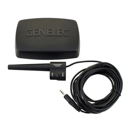
To set up a monitoring system you will need monitors and subwoofers, audio signal cables, GLM control network cables, GLM network adapter, GLM measurement microphone, and GLM 2.0 software. To set up a Genelec SAM system, ... -
Page 8: Cabling For Audio Signals
When you need both analog and digital audio cabling, it is possible to populate both analog and digital inputs and outputs on SAM products. GLM 2.0 allows Group configuration to be either analog or digital. Note that the 8320 features analog input only. -
Page 9: Analog 5.1 Surround Example
Genelec SAM – GLM 2.0 System Operating Manual page 9 of 39 Figure 3. Analog stereo cabling Analog 5.1 Surround Example Before cabling, turn off the power in all monitors and subwoofers. An example is shown in Figure 4. ... -
Page 10: Digital Audio, Stereo With A Subwoofer Example
Genelec SAM – GLM 2.0 System Operating Manual page 10 of 39 Digital Audio, Stereo with a Subwoofer Example Before cabling, turn off the power in all monitors and subwoofers. An example of the audio cabling for AES/EBU digital audio is shown in Figure 5. -
Page 11: Downloading And Installing Glm Software
Figure 6. Connections of GLM control network, measurement microphone, and computer Downloading and Installing GLM Software GLM software calibrates and controls Genelec SAM monitoring systems. The software is downloadable at www.genelec.com/glm. You must have sufficient rights to install software into your computer. Install the software following the instruction given by the software during the installation process. -
Page 12: Creating A Sam Monitor Layout
Genelec SAM – GLM 2.0 System Operating Manual page 12 of 39 The steps to create a GLM System Setup with a system layout and calibration are create a SAM monitoring system layout define one or more SAM monitoring groups ... -
Page 13: Creating A Sam Monitor Group
Genelec SAM – GLM 2.0 System Operating Manual page 13 of 39 When you drag, the real monitor plays an identification tone and flashes the front panel LED. The identification tones depend on the SAM product type and the tones can vary between products in the same setup. -
Page 14: Automatic Calibration Using Glm Autocal
Each monitor group has its own acoustic settings. This is one of the important features of GLM 2.0. Each setup file can contain several monitoring group definitions each with different AutoCal calibration settings. - Page 15 Genelec SAM – GLM 2.0 System Operating Manual page 15 of 39 To calibrate a monitoring group connect the calibration microphone to the GLM adapter place the microphone at the listening position, at ear height click the calibration microphone icon to start a measurement ...
-
Page 16: Aligning Subwoofer Phase With Glm Autophase
Genelec SAM – GLM 2.0 System Operating Manual page 16 of 39 Aligning Subwoofer Phase with GLM AutoPhase The purpose of the GLM AutoPhase is to set the subwoofer phase at the crossover frequency in relation to a selected monitor so that the combined response of the subwoofer-monitor system is flat across the crossover. -
Page 17: Basic Use Of Glm
Genelec SAM – GLM 2.0 System Operating Manual page 17 of 39 Basic Use of GLM The main page of the GLM software offers the basic monitoring system controls (Figure 14) system level selection and activation of Groups using group tabs ... -
Page 18: Group Tabs
Genelec SAM – GLM 2.0 System Operating Manual page 18 of 39 Group Tabs A group is activated by clicking the group tab. When the group tab is clicked, monitors and subwoofers belonging in the group are activated ... -
Page 19: Advanced Use Of Glm
Genelec SAM – GLM 2.0 System Operating Manual page 19 of 39 Advanced Use of GLM GLM is the most powerful tool available to calibrate and control a Genelec SAM monitoring system. The following chapters introduce advanced use of the GLM. Maximum Number of Groups Each system setup file can contain up to five groups. -
Page 20: Displaying Monitor And Subwoofer Data In Glm
Genelec SAM – GLM 2.0 System Operating Manual page 20 of 39 ‘View Info’ menu enables display of data set or measured in the monitors and subwoofers ‘ISS Power Saving’ menu sets the ISS go-to-sleep waiting time and can disable the ISS ... -
Page 21: Access To Monitor And Subwoofer Settings
Genelec SAM – GLM 2.0 System Operating Manual page 21 of 39 Access to Monitor and Subwoofer Settings Access to monitor and subwoofer acoustical calibration and settings is available by double-clicking on the monitor and subwoofer icons. You can also use the ‘Group’ system menu items to access monitor and subwoofer acoustical settings. -
Page 22: Access To Group Settings
Genelec SAM – GLM 2.0 System Operating Manual page 22 of 39 group name audio signal type, analog or AES/EBU digital monitors and subwoofers in the group (playing when this group is selected) and the ones that are not used in this group ... -
Page 23: Aes/Ebu Subframe A And B Selections
GLM 2.0 defaults to the common AES/EBU channel assignments (subframe A is left, B is right). To edit group settings specific to an individual monitor or subwoofer, click the monitor or subwoofer icon. -
Page 24: Group Setting Specific To A Single Monitor (83Xx Family)
Genelec SAM – GLM 2.0 System Operating Manual page 24 of 39 set the LFE channel gain Group setting specific to a single monitor (83xx family) This section explains the group-specific controls available for monitors. Table 3. Group settings for monitors (83xx family) -
Page 25: Group Setting Specific To A Single Subwoofer (73Xx Family)
This section explains the group-specific controls available for SAM subwoofers having only digital audio inputs. These subwoofer are fully compatible with GLM 2.0 but naturally cannot accept any analog input directly. You can use these for analog signal with an separate analog-to-digital... - Page 26 Genelec SAM – GLM 2.0 System Operating Manual page 26 of 39 Table 5. Group settings for legacy subwoofer, with analog input (72xx family) Setting Description View Subwoofer Name Name tag to help identify subwoofer (note) This subwoofer model has only digital inputs and cannot be used with analog signals.
-
Page 27: Using Bass Management Crossover Frequency Settings
Genelec SAM – GLM 2.0 System Operating Manual page 27 of 39 Using Bass Management Crossover Frequency Settings The subwoofer crossover frequency is normally set in the subwoofer group settings. When the crossover setting is marked ‘global’ this crossover setting is applied to all monitors in the group. -
Page 28: Reviewing The Autocal Result
Genelec SAM – GLM 2.0 System Operating Manual page 28 of 39 review the result by clicking on the monitor and subwoofer icons accept the calibration result with the ‘Confirm Calibration’ button Figure 18. Microphone layout for multipoint calibration... -
Page 29: Advanced Use Of Autophase
Genelec SAM – GLM 2.0 System Operating Manual page 29 of 39 Advanced use of AutoPhase AutoPhase, selects the subwoofer phase at crossover frequency with a selected monitor. The purpose of AutoPhase is to align the subwoofer phase with the reference monitor so that the frequency response across the bass management crossover is flat. -
Page 30: Editing Acoustic Calibrations
Genelec SAM – GLM 2.0 System Operating Manual page 30 of 39 Editing Acoustic Calibrations Acoustic Editors Acoustic settings editor opens with several methods double-click on a monitor or subwoofer icon in the main window right-clicking on the icon and select ‘Edit Acoustics’ menu ... -
Page 31: Descriptions Of The Acoustical Settings
Genelec SAM – GLM 2.0 System Operating Manual page 31 of 39 Descriptions of the Acoustical Settings Table 7. Acoustical settings Setting Description View Frequency Measured frequency response (red), room response graphs calibration filter (blue), compensated room frequency response (green). -
Page 32: Room Response Equalizer Controls
Genelec SAM – GLM 2.0 System Operating Manual page 32 of 39 Figure 21. Level and time-of-flight correction controls Room Response Equalizer Controls Each SAM monitor and subwoofer contains a set of tools to compensate for the acoustical influences of the room. These tools include high frequency shelving filters (filters 1 and 2), low frequency shelving filters (filters 3 and 4), and parametric notch filters (filters 5 to 20). -
Page 33: Stand-Alone Operation
Genelec SAM – GLM 2.0 System Operating Manual page 33 of 39 Stand-Alone Operation SAM monitors and subwoofers are set up and calibrated using GLM control network and GLM 2.0 user interface software. After setup, monitors, subwoofers, and the GLM adapter can also operate without having a computer connected to the GLM adapter. -
Page 34: Wireless Level Controller
Genelec SAM – GLM 2.0 System Operating Manual page 34 of 39 Figure 24. GLM adapter connections from left to right, USB to computer or to USB power supply, hardware level controller input, GLM measurement microphone input, GLM network and terminal connectors Using a USB power supply ... -
Page 35: Indications Summary
Genelec SAM – GLM 2.0 System Operating Manual page 35 of 39 Indications summary GLM indications summary Table 8. Indications summary icon icon action device LED action meaning and resolution Steady green Steady green Device is working normally and passes audio... -
Page 36: Monitor And Subwoofer Led Light Indications Summary
Genelec SAM – GLM 2.0 System Operating Manual page 36 of 39 Monitor and subwoofer LED light indications summary Table 9. Monitor and subwoofer LDE indications summary Device LED action Meaning and resolution Steady green Normal state Slowly blinking green... -
Page 37: Frequently Asked Questions
‘Group | Add Group’. Name the new group and make the necessary edits to it and click the ‘Confirm Group’ button. Next, place the Genelec calibration microphone at the second listening position and run calibration by double-clicking on the measurement microphone icon. -
Page 38: Can Analog And Digital Signal Sources Be Mixed
SAM monitor by selecting the subframe A or B. The GLM 2.0 software offers default values that cover the most common channel pairings (for example, in digital stereo, the subframe A is selected for the left monitor and the subframe B is... - Page 39 Fax +46 8 708 7071 genelec.usa@genelec.com No. 10 Jiuxianqiao Road Email info@genelec.com Chaoyang District Beijing, China Phone +86 (10) 5823 2014 Post code: 100015 Email genelec.china@genelec.com Genelec Document D0116R003. Copyright Genelec Oy 11. 2014. All data subject to change.