Table of Contents
Advertisement
®
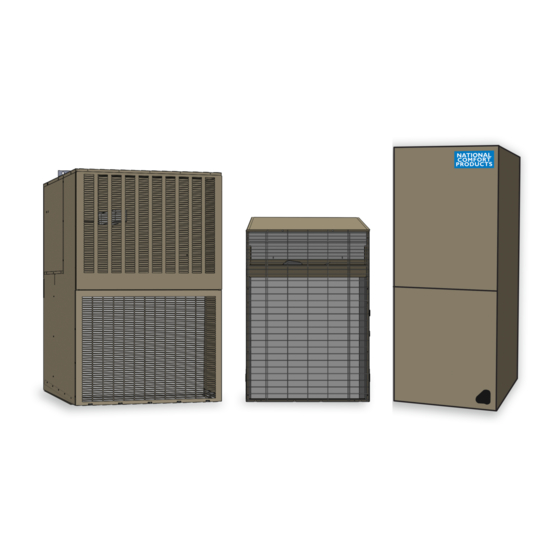
Comfort PaCk - Gas & Electric Units
Installation / Instruction Manual
Prepared Exclusively for Architects & Engineers
Thru-the-Wall
Heating & Cooling Comfort
FRONT View
BACK View
®
National Comfort Products
539 Dunksferry Road • Bensalem, PA 19020 • (215) 244-1400 • 1-800-523-7138 • Fax: (267) 638-1674
Installation & Maintenance Instruction Manual 02/25/15
Advertisement
Table of Contents

Summary of Contents for National Comfort Product Comfort Pack GAS
- Page 1 ® Comfort PaCk - Gas & Electric Units Installation / Instruction Manual Prepared Exclusively for Architects & Engineers Thru-the-Wall Heating & Cooling Comfort FRONT View BACK View ® National Comfort Products 539 Dunksferry Road • Bensalem, PA 19020 • (215) 244-1400 • 1-800-523-7138 • Fax: (267) 638-1674 Installation &...
-
Page 2: Table Of Contents
Installation/Instruction Manual for Architects & Engineers Introduction...........page 1 Specification.........page 2 - Features The Thru-the-Wall Comfort Pack..page 4 - AHRI - Easy Service Options - Unit Dimensions - CPG Submittal Package - CPE Submittal Package - Cross Reference List - CPG Specs - CPE Specs Unit Clearances........page 11 Locating the Unit(s).......page 12... -
Page 3: Introduction
Installation/Instruction Manual for Architects & Engineers Thru-the-Wall Heating & Cooling Multi-family complex using Comfort Packs produced by National Comfort Products Introduction This manual is offered to Architects and Engineers designing multi-family projects interested in National Comfort Products “Comfort Pack” to heat and cool the property. Local building codes must be applied when using our products. -
Page 4: Specification
Installation/Instruction Manual for Architects & Engineers Specification 1. PRODUCT NAME CPE Models – Electric heating with electric National Comfort Products – Comfort Pack – cooling. Where natural gas is not available National Refrigeration and Air Conditioning we offer heating packages of 5, 7.5, 10, 2. -
Page 5: Features
Installation/Instruction Manual for Architects & Engineers FEATURES: ENVIROMENTAL – Environmentally friendly refrigerant HCFC R410A EXTERNAL JUNCTION BOX - Each unit 5. Standard Controls & Components – equipped with a top mounted external Equiped to utlilize single, 2-stage, or clock junction box for ease of installation. thermostat. -
Page 6: The Thru-The-Wall Comfort Pack
Installation/Instruction Manual for Architects & Engineers The Comfort Pack Single Pack Vertical Unit (SPVU The Comfort Pack is classified as an SPVU. It is a single package unit that provides a ducted supply for both heating and cooling. The single package unit offers easy installation and service. - Page 7 Installation/Instruction Manual for Architects & Engineers COMFORT PACK DIMENSIONAL DRAWING CPG - COMFORT PACK DIMENSION DRAWING 20 1/8" 31 7/16" 28" 1 3/32" 7 11/16" 3 3/4" 15 13/16" 11 1/16" Junction Box 26 9/32" Supply Gas Connection 4 11/32" Low Voltage 43"...
-
Page 8: Cpg Submittal Package
Installation/Instruction Manual for Architects & Engineers CPG SUBMITTAL PACKAGE R-410A COMFORT PACK - GAS HEAT - ELECTRIC COOLING PROJECT: LOCATION: DATE: PURCHASER: ARCHITECT: ENGINEER: PO#: FOR REFERENCE: SUBMITTED BY: FOR APPROVAL: R-410A GAS HEAT MODELS ALL MODELS ARE RATED 208-230/1/60 RATED COOLING/HEATING MINIMUM MAXIMUM... -
Page 9: Cpe Submittal Package
Installation/Instruction Manual for Architects & Engineers CPE SUBMITTAL PACKAGE R-410A CPE SUBMITTAL PACKAGE R-410A COMFORT PACK - ELECTRIC HEAT - ELECTRIC COOLING COMFORT PACK - ELECTRIC HEAT - ELECTRIC COOLING MEETS DOE REQUIREMENTS FOR ALL UNITS. PROJECT: LOCATION: DATE: PURCHASER: ARCHITECT: ENGINEER: PO#:... -
Page 10: Cross Reference List
Installation/Instruction Manual for Architects & Engineers CROSS REFERENCE LIST COMFORT PACK NOTE: VERIFY HEATING OUTPUT BEFORE FOLLOWING CROSS REFERENCE. Our Current GAS MODELS THIS SHEET IS BASED ON MATCHING 80% EFFICIENCY MODELS. Models CPG R-22 MAGIC PAK MAGIC CHEF MAGIC CHEF MAGIC PAK R-410A CPG R-410A NOT AVAILABLE... - Page 11 Installation/Instruction Manual for Architects & Engineers COMFORT PACK -Gas Heat / Electric Cooling CPG - ELECTRICAL DATA INDOOR MINIMUM MAXIMUM OUTDOOR TOTAL MODEL VOLTAGE COMPRESSOR BLOWER CIRCUIT OVERCURRENT FAN MOTOR AMPS MOTOR AMPACITY PROTECTOR CPG41238-D 208-230/60/1 26.0 12.0 CPG41838-D 208-230/60/1 44.0 13.1 14.7...
- Page 12 Installation/Instruction Manual for Architects & Engineers COMFORT PACK -Electric Heat / Electric Cooling CPE - ELECTRICAL DATA INDOOR MINIMUM MAXIMUM OUTDOOR TOTAL MODEL VOLTAGE COMPRESSOR BLOWER CIRCUIT OVERCURRENT FAN MOTOR AMPS MOTOR AMPACITY PROTECTOR CPE41205-D 208-230/60/1 26.0 24.2 30.3 CPE41207-D 208-230/60/1 26.0 41.7...
-
Page 13: Unit Clearances
Installation/Instruction Manual for Architects & Engineers Unit Clearances For proper unit performance and maximum operating life please maintain the following minimum installation clearances below. Comfort Pack units must be installed through an outside wall. Confined spaces and/or covered areas should be avoided. Consult the factory if unclear of clearances required. Units must be installed a minimum of 12”... -
Page 14: Locating The Unit(S)
Installation/Instruction Manual for Architects & Engineers Locating the Unit(s) Minimum Vertical Clearance 60” between units Minimum Horizontal Clearance 12” between two units National Comfort Products recommends a minimum of 30”away from plants and shrubbery. -
Page 15: Service Access
Installation/Instruction Manual for Architects & Engineers Service Access One of the most important clearances is the space inside the room that houses the unit. It is important to leave 29” of clearance behind the unit for removal of the chassis for cleaning and servicing. -
Page 16: Venting
Installation/Instruction Manual for Architects & Engineers Venting The venting system is an integral part of the heater as shipped to you. Do not modify or add to the vent system. The heat system includes an exhaust blower. The blower draws the gas and air required for combustion through the heat exchanger, and forces the product of combustion to the outside. -
Page 17: Vent Termination Clearances
Installation/Instruction Manual for Architects & Engineers Vent Termination Clearances for Direct Vented Installations in the USA and Canada Balcony - with perpendicular side wall Inside Corner Detail Combustible & Noncombustible M = 24” (610 mm) P = 20” (508 mm) Fixed Closed Operable... -
Page 18: Walls
Installation/Instruction Manual for Architects & Engineers Walls Wall Sleeve (CPWS) Our wall sleeve must be field assembled and easily forms a box with mounting brackets, guides, and seals. It should be installed with a non-hardening caulk into the opening of the wall. The sleeve should be installed 3/4”... -
Page 19: Wall Construction
Installation/Instruction Manual for Architects & Engineers Wall Construction The wall sleeve is designed to support the unit but the wall itself must be adequate to support the unit. When this is an issue a support is needed at the base of the unit. For wood frame walls;... - Page 20 Installation/Instruction Manual for Architects & Engineers 15 27/32” Sleeve Adapter Option 28 3/16” (CPWSA) 5 1/2" The Comfort Pack Wall Sleeve 5 3/4" Adapter is used for certain replacement installations. USED WItH GaS When replacing an older or ELECtrIC UNItS. Armstrong model with a Comfort Pack, where the original unit height was 48”, the Wall Sleeve...
-
Page 21: Sealing Of The Unit
Installation/Instruction Manual for Architects & Engineers Sealing of the Unit Water Water is drained from the unit from channels and weep holes built into the unit itself. Different gaskets and seals are installed in the unit from the factory. The unit is designed to take on water from the outside of the unit mounted 3/4”... -
Page 22: Ductwork
Installation/Instruction Manual for Architects & Engineers Ductwork Supply NOTE: Always perform a proper heat loss calculation before specifying the furnace size. This ensures that the furnace is sized to adequately and economically heat the building while also providing the correct airflow for your application. Central cooling and heating equipment is only as efficient as the duct system that carries the cooled or heated air. - Page 23 Installation/Instruction Manual for Architects & Engineers The supply ductwork is to be field installed and sized properly for the cfm of the unit. Under sizing of plenums and ductwork can relate to excessive static pressure and poor airflow causing multiple problems to occur. When replacing a competitor’s unit, the ductwork supply may require an alteration.
-
Page 24: Return
Installation/Instruction Manual for Architects & Engineers Return • RETURN AIR TEMPERATURE MAINTAINED BETWEEN 55°F (13°C) AND 80°F (27°C) The return ductwork is be installed in accordance with the National Fuel Gas Code 10.3.7.3 and 10.3.7.4. All Comfort Pack units to date are approved for an open bottom return so long as the unit is installed in accordance with National Fuel Gas Code 10.3.7.3 and 10.3.7.4 as well as local building and fire codes. -
Page 25: Drainage
Installation/Instruction Manual for Architects & Engineers Drainage A drain pan is positioned underneath the evaporator coil to collect condensate. A 3/4” flexible tube included with the unit should be connected to the drain connection on the drain pan so it can be easily disconnected for chassis removal. A 2” deep trap should be installed close to the pan. -
Page 26: Electrical
Installation/Instruction Manual for Architects & Engineers Electrical High Voltage The unit is factory wired for 230 Volts AC Single Phase 60 Hertz. The operating voltage is from 197 VAC to 253 VAC. In order to operate the unit at 208 VAC the primary side of the transformer must be changed from 240 volt connection to the 208 volt connection. -
Page 27: Service
Installation/Instruction Manual for Architects & Engineers Service Air Filter The unit comes equipped with a 16” x 25” x 1” filter on the cooling chassis. This filter should be replaced regularly to assure that the unit provides optimal performance and energy efficiency. -
Page 28: Warranty
Installation/Instruction Manual for Architects & Engineers Warranty Parts Warranty The Comfort Pack warranty covers five (5) years on parts (gas and electric), five (5) years on compressor (gas and electric), and ten (10) years on heat exchanger (gas only), from the date of installation (must have receipt of purchase and/or installation invoice). - Page 29 LIMITED EXTENDED PROTECTION WARRANTY FOR NATIONAL COMFORT PRODUCTS (NCP) BENSALEM, PA COMFORT PACK GAS UNITS FAILURE TO MAINTAIN YOUR EQUIPMENT WILL VOID THIS WARRANTY Your new NCP product must be properly installed, operated and maintained in accordance with the unit’s instructions, operation and maintenance instructions provided with each NCP unit.
-
Page 30: About Us
Installation/Instruction Manual for Architects & Engineers About Us National Comfort Products is a Division of National Refrigeration and Air Conditioning located in Bensalem, PA. Consisting of three facilities we bend, cut and punch all of our metal for our products. All units are proudly built in Bensalem, PA USA. - Page 31 Installation/Instruction Manual for Architects & Engineers The Industry’s Choice for Heating & Cooling Comfort for all types of Multi-Family Construction! MULTi-FAMiLY COMPLex SHOwiNG COMFORT PACK UNiTS...
-
Page 32: Notes
Installation/Instruction Manual for Architects & Engineers Notes... - Page 34 ® National Comfort Products 539 Dunksferry Road • Bensalem, PA 19020-5908 (800) 523-7138 Fax (215) 638-1674 Installation & Maintenance Instruction Manual-Comfort Pack 02/25/15...