Table of Contents
Advertisement
Service Literature
ML193UH series units are high−efficiency gas furnaces
manufactured with Lennox DuralokPlust aluminized
steel clamshell−type heat exchangers, with a stainless steel
condensing coil. ML193UH units are available in heating
input capacities of 44,000 to 132,000 Btuh (13 to 38.6 kW)
and cooling applications from 2 through 5 tons (7.0 through
17.6 kW). Refer to Engineering Handbook for proper sizing.
Units are factory equipped for use with natural gas. A kit is
available for conversion to LPG operation. All ML193UH
units are equipped with a hot surface ignition system. The
gas valve is redundant to assure safety shut−off as re-
quired by C.S.A.
The heat exchanger, burners and manifold assembly can be
removed for inspection and service. The maintenance section
gives a detailed description on how this is done.
All specifications are subject to change. Procedures outlined
in this manual are presented as a recommendation only
and do not supersede or replace local or state codes.
WARNING
Electric shock hazard. Can cause injury
or death. Before attempting to perform
any service or maintenance, turn the
electrical power to unit OFF at discon-
nect switch(es). Unit may have multiple
power supplies.
Table of Contents
. . . . . . . . . . . . . . . . . . . . . . . . . . . . . . . . .
. . . . . . . . . . . . . . . . . . . . . . . . . .
. . . . . . . . . . . . . . . . . . . . . . . . . . . . .
. . . . . . . . . . . . . . . . . . . . . . . . . . . . . . . . . . .
. . . . . . . . . . . . . . . . . . . . . . . . . . . . . . .
ML193UH SERIES UNITS
2
3
. . . . . . . . . . . . . . . . . . . . . .
4
7
. . . . . . . . . . . . . . . . . . . .
14
35
. . . . . . . . . . . . . .
36
. . . . . . . . . . . . . . . . . .
38
39
. . . . . . .
41
. . . . . . . . . . .
46
Corp. 1025−L5
Improper installation, adjustment, alteration, service
or maintenance can cause property damage, person-
al injury or loss of life. Installation and service must
be performed by a licensed professional installer (or
equivalent), service agency or the gas supplier.
Sharp edges.
Be careful when servicing unit to avoid sharp edges
which may result in personal injury.
Page 1
ML193UH
WARNING
WARNING
© 2010 Lennox Industries Inc.
Litho U.S.A.
Advertisement
Table of Contents

Related Manuals for Lennox ML193UH045P36B


Summary of Contents for Lennox ML193UH045P36B
-
Page 1: Table Of Contents
Service Literature ML193UH SERIES UNITS ML193UH series units are high−efficiency gas furnaces manufactured with Lennox DuralokPlust aluminized steel clamshell−type heat exchangers, with a stainless steel condensing coil. ML193UH units are available in heating input capacities of 44,000 to 132,000 Btuh (13 to 38.6 kW) and cooling applications from 2 through 5 tons (7.0 through... -
Page 2: Specifications
SPECIFICATIONS Model No. ML193UH045P36B ML193UH070P24B ML193UH070P36B ML193UH090P36C Heating AFUE Performance Input - Btuh 44,000 66,000 66,000 88,000 Output - Btuh 42,000 62,000 62,000 83,000 Temperature rise range - °F 25 - 55 50 - 80 40 - 70 50 - 80 Gas Manifold Pressure (in. -
Page 3: Optional Accessories
OPTIONAL ACCESSORIES - MUST BE ORDERED EXTRA “B” Width “C” Width “D” Width Models Models Models CABINET ACCESSORIES Horizontal Suspension Kit - Horizontal only 51W10 51W10 51W10 Return Air Base - Upflow only 50W98 50W99 51W00 CONDENSATE DRAIN KITS Condensate Drain Heat Cable 6 ft. -
Page 4: Blower Performance Data
BLOWER DATA ML193UH045P36B PERFORMANCE (Less Filter) ML193UH090P36C PERFORMANCE (Less Filter) Air Volume / Watts at Various Blower Speeds Air Volume / Watts at Various Blower Speeds External External Medium- Medium- Medium- Medium- Static Static High High High High Pressure Pressure in. - Page 5 BLOWER DATA ML193UH110P60C PERFORMANCE (Less Filter) Air Volume / Watts at Different Blower Speeds Bottom Return Air, Side Return Air with Optional Return Single Side Return Air − Air volumes in bold require field External Air Base, Return Air from Both Sides or Return Air from fabricated transition to accommodate 20 x 25 x 1 in.
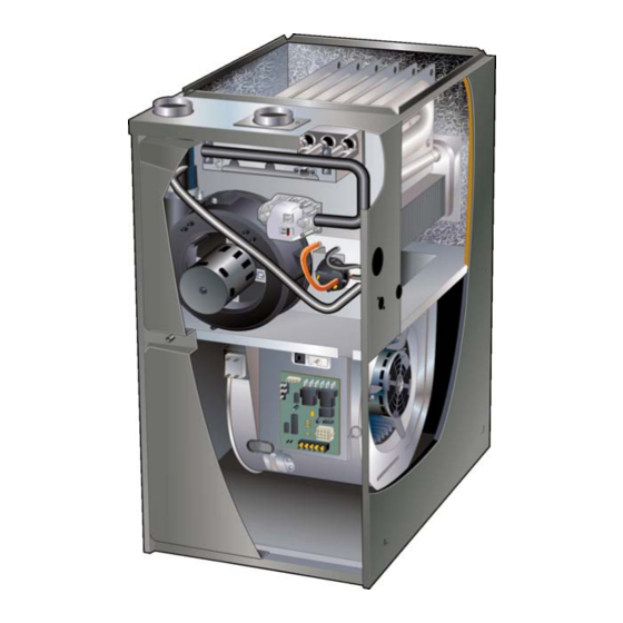
- Page 6 ML193UH PARTS IDENTIFICATION FLEXIBLE NO−HUB EXHAUST COLLAR BURNER BOX TOP CAP MANIFOLD ASSEMBLY GAS VALVE DuralokPlus HEAT EXCHANGER ASSEMBLY FLUE COLLAR COMBUSTION AIR INDUCER BURNER ACCESS PANEL CABINET BAG ASSEMBLIES (shipping location) PRIMARY LIMIT COMBUSTION AIR PRESSURE SWITCH SIGHT BLOWER GLASS COLD END ASSEMBLY...
-
Page 7: I−Unit Components
I−UNIT COMPONENTS integrated control also features two LED lights (DS1 red and DS2 green) for troubleshooting and two accessory ML193UH unit components are shown in figure 1. The terminals rated at (1) one amp. The integrated control also combustion air inducer, gas valve and burners can be ac- cessed by removing the burner access panel. - Page 8 After the 15−second pre−purge period, the ignitor warms up changing the jumper position across the five pins on the integrated control. The unit is shipped with a factory fan off for 20 seconds during which the gas valve opens at 19 sec- setting of 90 seconds.
- Page 9 The integrated control is equipped with two LED lights for troubleshooting. The diagnostic codes are listed below in table 3. TABLE 3 DIAGNOSTIC CODES Make sure to Identify LED’S Correctly. LED #1 (Red) LED #2 (Green) DESCRIPTION Power on − Normal operation. SIMULTANEOUS SIMULTANEOUS Also signaled during cooling and continuous fan.
- Page 10 B−Heating Components NOTE − The ML193UH furnace contains electronic components that are polarity sensitive. Make sure that Combustion air inducer (B6), primary limit control (S10), the furnace is wired correctly and is properly grounded. SureLight ignitor, burners, flame rollout switch (S47), gas valve (GV1), combustion air prove switch (S18), and clam- shell heat exchangers are located in the heating compart- 3.
- Page 11 4. Primary Limit Control (Figure 7) an orifice which is precisely matched to the burner input. See table 4 for orifice size. The burner is supported by the Primary limit (S10) used on ML193UH units is located in the orifice and will easily slide off for service. A flame retention heating vestibule panel.
- Page 12 8. Combustion Air Inducer (B6) Pressure Switch & Cold End Header Box All ML193UH units use a combustion air inducer to move air through the burners and heat exchanger during heat- ing operation. The blower uses a shaded pole 120VAC motor.
- Page 13 Measuring Pressure Differential RED TUBING NEGATIVE BLACK TUBING POSITIVE 1 − Remove thermostat demand and allow unit to 4 − Operate unit and observe manometer reading. cycle off. Readings will change as heat exchanger warms. 2 − Install a tee in the negative (−) line (red tubing) and a a.
-
Page 14: Placement And Installation
II−PLACEMENT AND INSTALLATION In addition to providing combustion air, fresh outdoor air di- lutes contaminants in the indoor air. These contaminants may include bleaches, adhesives, detergents, solvents Combustion, Dilution & Ventilation Air and other contaminants which can corrode furnace compo- If the ML193UH is installed as a Non−Direct Vent Fur- nents. - Page 15 If air from outside is brought in for combustion and ventila- EQUIPMENT IN CONFINED SPACE − ALL AIR FROM INSIDE tion, the confined space must have two permanent open- ings. One opening shall be within 12 inches (305 mm) of the top of the enclosure and one opening within 12 inches (305 mm) of the bottom.
- Page 16 Use PVC primer and solvent cement or ABS solvent cement EQUIPMENT IN CONFINED SPACE − meeting ASTM specifications, refer to Table 7. As an alter- ALL AIR FROM OUTSIDE nate, use all purpose cement, to bond ABS, PVC, or CPVC pipe when using fittings and pipe made of the same materi- ROOF TERMINATED als.
-
Page 17: Joint Cementing Procedure
† Termination kits 44W92, 44W93, 30G28 and 81J20 approved for use in Canadian installations to meet CSAB149. †† The 44W92 Concentric kit is provided with a 1−1/2" accelerator which must be installed on the exhaust outlet when this kit is used with the ML193UH045P36B, ML193UH070P24B and ML193UH070P36B furnaces. -
Page 18: Venting Practices
8 − After assembly, wipe excess cement from pipe at end REPLACING FURNACE THAT WAS of fitting socket. A properly made joint will show a PART OF A COMMON VENT SYSTEM bead around its entire perimeter. Any gaps may indi- cate an improper assembly due to insufficient sol- CHIMNEY OR GAS... -
Page 19: Vent Piping Guidelines
Refer to table 11. In some applications which permit the use of several differ- ent sizes of vent pipe, a combination vent pipe may be used. Contact Lennox’ Application Department for assis- Which needs Intake or tance in sizing vent pipe in these applications. - Page 20 TABLE 10 Maximum Allowable Vent Length in Feet Standard Termination at Elevation 0 − 10,000 ft. Pipe 2" 2−1/2" 3" Size Model Number Of 90° Ebows Used Concentric Termination Elevation 0 − 10,000 ft. Pipe 2" 2−1/2" 3" Size Model Number Of 90°...
- Page 21 TYPICAL EXHAUST PIPE CONNECTIONS AND CONDENSATE TRAP INSTALLATION IN UPFLOW DIRECT OR NON−DIRECT VENT APPLICATIONS Pipe size determined in table 10 2” 2” 2” 2” 2” 3” TRANSITION EXHAUST 2” TRAP DO NOT transition from smaller to larger Use only the pipe in horizontal runs factory−supplied trap.
- Page 22 TYPICAL AIR INTAKE PIPE CONNECTIONS IN UPFLOW DIRECT VENT APPLICATIONS Pipe size determined in table 10 3” 2” TRANSITION *2” 2” AIR INTAKE 2” 2” 2” TRAP Use only the factory−supplied trap. Trap can be installed on either side of cabinet within 5 ft.
- Page 23 Intake Piping TYPICAL AIR INTAKE PIPE CONNECTIONS The ML193UH furnace may be installed in either direct HORIZONTAL NON−DIRECT VENT APPLICATIONS (Horizontal Right−Hand Air Discharge Application Shown) vent or non−direct vent applications. In non−direct vent applications, when intake air will be drawn into the furnace from the surrounding space, the indoor air quality must be considered and guidelines listed in Combustion, Dilution PVC pipe...
- Page 24 National Fuel to prevent freeze−ups. Heating cable installation kit is Gas Code ANSI Z223−1/NFPA 54 in U.S.A., and current available from Lennox. See Condensate Piping section CSA−B149 Natural Gas and Propane Installation Codes in for part numbers.
-
Page 25: Vent Termination Clearances
‡ Permitted only if veranda, porch, deck or balcony is fully open on a minimum of two sides beneath the floor. Lennox recommends avoiding this location if possible. FIGURE 27 Page 25... - Page 26 ‡ Permitted only if veranda, porch, deck or balcony is fully open on a minimum of two sides beneath the floor. Lennox recommends avoiding this location if possible. FIGURE 28 Page 26...
- Page 27 Details of Intake and Exhaust Piping Terminations for FIELD SUPPLIED WALL TERMINATION OR Direct Vent Installations (15F74) WALL RING TERMINATION KIT NOTE − In Direct Vent installations, combustion air is tak- en from outdoors and flue gases are discharged to out- NOTE −...
- Page 28 5. On field supplied terminations for side wall exit, ex- FIELD SUPPLIED WALL TERMINATION OR haust piping may extend a maximum of 12 inches (15F74) WALL RING TERMINATION KIT With INTAKE ELBOW (305mm) for 2" PVC and 20 inches (508mm) for 3" (76mm) PVC beyond the outside wall.
-
Page 29: Front View
1 1/2" (38mm) accelerator EXHAUST VENT Front View provided on 71M80 & 44W92 EXHAUST kits for ML193UH045P24B, SIZE VENT 070P24B & 070P36B TERMINATION PIPE PER INTAKE FLASHING TABLE 11. 12” (305mm) INTAKE (Not Furnished) Minimum Above Average Snow Accumulation Top View 1/2"... -
Page 30: Snow Accumulation
WALL TERMINATION KITS (CLOSE−COUPLE) EXTENDED VENT FOR GRADE CLEARANCE 2 inch (51 mm) 22G44 (US) 3 inch (76 mm) 44J40 (US) If intake and exhaust pipe is less than 12 in. (305 mm) above snow accumulation or other obstructions, field− fabricated piping must be installed. - Page 31 ML193UH DIRECT VENT APPLICATION 12" (305mm) MAX. for 2" (51mm) 20" (508mm) MAX. for 3" (76mm) USING EXISTING CHIMNEY 1/2" (13mm) ARMAFLEX STRAIGHT−CUT OR INSULATION IN ANGLE−CUT IN DIRECTION 3"−8" UNCONDITIONED SPACE 1/2" (13mm) OF ROOF SLOPE * (76mm−203mm) ARMAFLEX FIELD−PROVIDED INSULATION REDUCER MAY...
- Page 32 Heating cable kit is up to 5´ away from the furnace. Use PVC pipe to connect available from Lennox in various lengths; 6 ft. (1.8m) − trap to furnace condensate outlet. Piping from furnace kit no.
- Page 33 CAUTION A separate drain line must be run to the drain from the condensate trap. DO NOT connect the conden- sate trap drain into the drain line from the evaporator coil. ML193UH with Cooling Coil Condensate trap and evaporator coil must drain separately as shown.
- Page 34 TRAP / DRAIN ASSEMBLY USING 1/2" PVC OR 3/4" PVC OPTIONAL Condensate Drain Connection Adapter 1/2 inch slip X Adapter 1/2 inch slip X 1/2 inch mpt (Not Furnished) Condensate Drain 1/2 inch mpt (Not Furnished) Connection In Unit Vent 90°...
-
Page 35: Start-Up
III−START-UP 2 − Set the thermostat to the lowest setting. 3 − Turn off all electrical power to the unit. A−Preliminary and Seasonal Checks 4 − This furnace is equipped with an ignition device which 1 − Inspect electrical wiring, both field and factory installed automatically lights the burners. -
Page 36: Heating System Service Checks
Gas Leak Detector is strongly recommended. It is available 3 − While waiting for the unit to stabilize, observe the through Lennox under part number 31B2001. See Corp. flame. Flame should be stable and should not lift from 8411−L10, for further details. - Page 37 TABLE 13 F−High Altitude Supply Line and Manifold Pressure (inches w.c.) NOTE − In Canada, certification for installations at eleva- tions over 4500 feet (1372 m) is the jurisdiction of local au- Manifold Pres- Line Unit Fuel thorities. sure Pressure ML193UH units require no manifold pressure adjustments Nat.
-
Page 38: Typical Operating Conditions
2 − Generally, blower operation is set at thermostat sub- base fan switch. With fan switch in ON position, blower A transducer (Part #78H5401 available from Lennox Repair operates continuously. With fan switch in AUTO position, Parts) is required to measure flame signal if meter used will not blower cycles with demand or runs continuously while read a low micro amp signal. -
Page 39: Maintenance
VI−MAINTENANCE 3 − Check amp−draw on the blower motor with blower ac- cess panel in place. Motor Nameplate__________Actual__________ Winterizing and Condensate Trap Care WARNING 1 − Turn off power to the furnace. 2 − Have a shallow pan ready to empty condensate water. ELECTRICAL SHOCK, FIRE, OR EXPLOSION HAZARD. - Page 40 20 − Remove top cap screws to allow top cap to be tilted up- 41 − Reconnect gas supply line to gas valve. ward to allow clearance for removing heat exchanger. 42 − Reconnect flame roll−out switch wires. 21 − Remove two screws from the front cabinet flange at 43 −...
-
Page 41: Sequence Of Operation And Flow Charts
VII−WIRING DIAGRAM AND SEQUENCE OF OPERATION 1 − When there is a call for heat, W1 of the thermostat en- 5 − Gas valve opens for a 4−second trial for ignition ergizes W of the furnace control with 24VAC. 6 − Flame is sensed, gas valve remains open for the heat 2 −... -
Page 42: Heating Sequence Of Operation
Sequence of Operation Flow Chart HEATING SEQUENCE OF OPERATION ABNORMAL HEATING MODE NORMAL HEATING MODE POWER ON GAS VALVE OFF. COMBUSTION AIR INDUCER OFF. INDOOR BLOWER DELAY OFF. CONTROL SELF−CHECK OKAY? LED #1 ON LED #2 ON (RESET CONTROL BY TURNING MAIN POWER OFF.) POLARITY REVERSED. - Page 43 HEATING SEQUENCE CONTINUED NORMAL HEATING MODE ABNORMAL HEATING MODE 15-SECOND COMBUSTION AIR INDUCER PREPURGE INITIATED BY CLOSED PRESSURE SWITCH. LEDS SIGNAL ALTERNATING FAST FLASH UNTIL IS VOLTAGE ABOVE 90 VOLTS? IGNITOR WARM-UP −− 20 SECONDS. VOLTAGE IS ABOVE 95 VOLTS, THEN RESTARTS HEATING 4-SECOND TRIAL FOR IGNITION.
- Page 44 COOLING SEQUENCE OF OPERATION NORMAL COOLING MODE ABNORMAL COOLING MODE POWER ON IGNITION CONTROL MAIN POWER ON. GAS VALVE OFF. COMBUSTION AIR INDUCER OFF. INDOOR BLOWER OFF WITH NORMAL DELAY. CONTROL SELF DIAGNOSTIC CHECK. SIGNAL CIRCUIT BOARD FAILURE AT LED. IS CONTROL OPERATING NORMALLY? INTERRUPT MAIN POWER TO RESET CONTROL.
- Page 45 CONTINUOUS HEAT SPEED FAN SEQUENCE OF OPERATION LED: SLOW FLASH RATE REMAINS UNCHANGED THROUGHOUT SEQUENCE. MANUAL FAN SELECTION MADE AT THERMOSTAT. CONTROL (G) ENERGIZES SYSTEM FAN AT HEAT SPEED. EAC TERMINAL IS ENERGIZED. HUM TERM. ENERGIZES THERMOSTAT CALLS FOR HEAT (W). WITH COMB.
-
Page 46: Integrated Control Troubleshooting
VIII−Integrated Control Troubleshooting Chart UPON INITIAL POWER UP, REMOVE ALL THERMOSTAT DEMANDS TO THE UNIT PROBLEM: 1 UNIT FAILS TO OPERATE IN THE COOLING, HEATING, OR CONTINUOUS FAN MODE Condition Possible Cause Corrective Action / Comments 1.1.1 ACTION 1 − Check 120V main voltage. −... - Page 47 PROBLEM 1: UNIT FAILS TO OPERATE IN THE COOLING, HEATING, OR CONTINUOUS FAN MODE Condition Possible Cause Corrective Action / Comments ACTION 1 − Check that the unit is properly 1.5.1 ground. − Diagnostic lights flash the improper ACTION 2 − Install a proper main ground to the Improper ground to the unit.
- Page 48 PROBLEM 2: UNIT FAILS TO FIRE IN THE HEATING MODE, COMBUSTION AIR INDUCER DOES NOT ENERGIZE (CONT.). Condition Possible Cause Corrective Action/Comments − Unit operates with a cooling and con- 2.3.1 ACTION 1 − Check for correct wiring and loose tinuous fan demand.
- Page 49 PROBLEM 4: UNIT FAILS TO FIRE IN THE HEATING MODE, COMBUSTION AIR BLOWER ENERGIZES, IGNITOR IS ENERGIZED. Condition Possible Cause Corrective Action/Comments ACTION 1 − Check line pressure at the gas valve. 4.1.1 Pressure should not exceed 13" WC for both nat- −...
- Page 50 ACTION 2 − Seal leakage if possible, replace secondary heat exchanger, and com- heat exchanger if necessary, tag and return heat exchanger to proper Lennox personnel. bustion air blower. 5.3.4 ACTION 1 − Check for sooting deposits or other restrictions in the heat exchanger assembly.
- Page 51 PROBLEM 6: CONTROL SIGNALS LOW FLAME SENSE DURING HEATING MODE Condition Possible Cause Corrective Action/Comments 6.1.1 ACTION 1 − Check the sensor rod for proper loca- − Unit operates correctly but the diag- tion on the burner. Properly locate the sensor rod Sensor rod is improperly located on or replace if rod cannot be located correctly.