Table of Contents
Advertisement
harman/kardon
harman/kardon
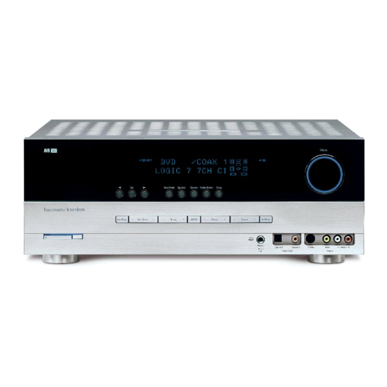
AVR 347/230
AVR 350/230
7 x 55W 7.1 CHANNEL A/V RECEIVERS
ESD WARNING
BASIC SPECIFICATIONS
AVR 347 PACKAGE LIST AND PARTS
AVR 347 DISASSEMBLY
AVR 347 DISASSEMBLY PROCEDURE
Avr347 Exploded View AND PARTS 11
AVR350 PACKAGE LIST AND PARTS
(For Semiconductor Pinouts, see separate file )
Released EU2008
CONTENTS
2
AVR 350 DISASSEMBLY
3
AVR 350 EXPLODED VIEW AND PARTS
4
ELECTRICAL PARTS LIST
4
PCB DRAWINGS
5
BLOCK DIAGRAM
6
7
AMP BIAS ADJUSTMENT
12
harman/kardon, Inc.
250 Crossways Park Dr.
Woodbury, New York, 11797
AVR 347/230 - AVR 350/230 Service Manual
Service Manual
Rev 0, 07/2008
13
14
15
74
83
84
85
86
Page 1 of 95
Advertisement
Table of Contents

Related Manuals for Harman Kardon AVR 347/230


Summary of Contents for Harman Kardon AVR 347/230
-
Page 1: Service Manual
AVR 347/230 - AVR 350/230 Service Manual harman/kardon Service Manual AVR 347/230 AVR 350/230 7 x 55W 7.1 CHANNEL A/V RECEIVERS CONTENTS ESD WARNING AVR 350 DISASSEMBLY BASIC SPECIFICATIONS AVR 350 EXPLODED VIEW AND PARTS TROUBLESHOOTING GUIDE ELECTRICAL PARTS LIST... - Page 2 AVR 347/230 - AVR 350/230 Service Manual Some semiconductor (solid state) devices can be damaged easily by static electricity. Such components commonly are called Electrostatically Sensitive (ES) Devices. Examples of typical ES devices are integrated circuits and some field effect transistors and semiconductor "chip"...
-
Page 3: Technical Specifications
AVR 347/230 - AVR 350/230 Service Manual Technical Specifications Audio Section FM Tuner Section Stereo Mode Frequency Range 87.5–108MHz Continuous Average Power (FTC) Usable Sensitivity IHF 1.3 µV/13.2dBf Signal-to-Noise Ratio Mono/Stereo: 70/68dB (DIN) 70 Watts per channel, 20Hz–20kHz, Distortion Mono/Stereo: 0.2/0.3%... -
Page 4: Troubleshooting Guide
AVR 347/230 - AVR 350/230 Service Manual Troubleshooting Guide SYMPTOM CAUSE SOLUTION Unit does not function when Main • No AC Power • Make certain AC power cord is plugged Power Switch 1 is pushed into a live outlet •... -
Page 5: Accessories/In The Box
AVR 347/230 - AVR 350/230 Service Manual AVR347 2. Package Drawing 1. Instruction manual ass'y - Accessories MICROPHONE ASS'Y MANUAL ASS'Y CARD WARRANTY POLY BAG AM LOOP ANTENNA ASS'Y BATTERY ASS'Y REMOCON ASS'Y SNOW PAD (L) SNOW PAD (R) -
Page 6: Disassembly Views
AVR 347/230 - AVR 350/230 Service Manual DISASSEMBLY AVR347 1. Removing the Top Cabinet 3. Removing the Rear Panel Remove the Screws Remove the Screws 20 21 25 26 32 33 4. Removing the Main PCB Remove the Screws 2. -
Page 7: Disassembly
AVR 347/230 - AVR 350/230 Service Manual DISASSEMBLY PROCEDURE (AVR347) <1> TOP-CABINET(21) REMOVAL 1. Remove 13 screws(S1,S7) and then remove the Top-cabinet. <2> FRONT PANEL ASS’Y REMOVAL 1. Remove the Top-cabinet, referring to the previous step<1>. 2. Disconnect the card cable between connector(CN72-17p) on the Fip PCB(37-1) and connector(CN72) on the Input PCB(39-1). - Page 8 AVR 347/230 - AVR 350/230 Service Manual 3. Remove the Fip PCB(37-1), referring to the previous step<6>. 4. Remove 10 screws(S2) and then remove the Key PCB(37-2). <8>TUNER MODULE(43) REMOVAL 1. Remove the Top-cabinet, referring to the previous step<1>.
- Page 9 AVR 347/230 - AVR 350/230 Service Manual <13>RS232 PCB(37-7) REMOVAL 1. Remove the Top-cabinet, referring to the previous step<1>. 2. Remove the Hudson PCB(42), referring to the previous step<9>. 3. Remove the Video PCB(41), referring to the previous step<10>.
- Page 10 AVR 347/230 - AVR 350/230 Service Manual from the lead wire(BN90) on the A-BUS PCB(39-3). 3. Disconnect the card cable between connector(CN16-12P) on the Input PCB(39-1). and connector(BN16-12P) on the A-BUS PCB(39-3). 4. Remove 3screws(S13) and then remove the A-BUS PCB ASS’Y(39-3).
-
Page 11: Exploded View
AVR 347/230 - AVR 350/230 Service Manual AVR347 EXPLODED VIEW 37-7 40-3 40-1 39-2 40-4 39-4 39-1 40-5 39-6 39-3 38-2 38-1 40-7 40-2 DESCRIPTION PARTS NO. Q,ty REMARK ORNAMENT,VOLUME CGU1A318Z CAP,VOLUME CGX1A338MBC63 HOLDER,VOLUME CMH1A214 INDICATOR,VOLUME CGL1A222 WINDOW ASS'Y... - Page 12 AVR 347/230 - AVR 350/230 Service Manual Page 12 of 95...
- Page 13 AVR 347/230 - AVR 350/230 Service Manual Page 13 of 95...
- Page 14 AVR350/230 EXPLODED VIEW harman/kardon AVR 347/230 - AVR 350/230 Service Manual 40-3 37-7 40-1 40-4 39-2 39-1 40-5 39-6 39-3 38-2 38-1 40-7 39-5 40-2 DESCRIPTION PARTS NO. Q,ty REMARK ORNAMENT,VOLUME CGU1A318Y CAP,VOLUME CGX1A338MBC63 HOLDER,VOLUME CMH1A214 INDICATOR,VOLUME CGL1A222 BADGE, HARMAN/KARDON...
-
Page 15: Parts List
AVR 347/230 - AVR 350/230 Service Manual AVR 347/230 and AVR 350/230 Electrical Parts List Description Value Ref. # Part Number CARTAVR347/230 REMOCON TRANSMITTER ASS'Y ASS'Y CGL1A222 INDICATOR , VOLUME INDICATOR CGUAVR345 WINDOW ASS'Y ASS'Y CGB1A170Z BADGE , AVR... - Page 16 AVR 347/230 - AVR 350/230 Service Manual FRONT PANEL ASSY Description Value Ref. # Part Number CGWAVR347/230 FRONT PANEL ASS'Y ASS'Y CBC1A158MBZG27 KNOB , MOMS KNOB CBT1A1026MMZG27 KNOB , POWER KNOB CBT1A1027K128 KNOB , DISPLAY KNOB CBT1A1028MBYG27 KNOB , FUNCTION...
- Page 17 AVR 347/230 - AVR 350/230 Service Manual BOTTOM CHASSIS ASS'Y Description Value Ref. # Part Number CTW3+8JR SCREW SCREW CUA3A229 CHASSIS , BOTTOM CHASSIS BN92 CWZSR4001BN91A WIRE ASS'Y ASS'Y CLZ9W003Z FERRITE , RING 29X7.7X19 CB11 CWC1B2A17A100B CABLE , CARD (1MM) 17PIN...
- Page 18 AVR 347/230 - AVR 350/230 Service Manual FRONT PCB ASSY Description Value Ref. # Part Number C820 CCEA1HH100T CAP , ELECT 10UF 50V C821 CCEA1EH470T CAP , ELECT 47UF 25V C822 CCEA1EH470T CAP , ELECT 47UF 25V C823 CCEA1HH100T...
- Page 19 AVR 347/230 - AVR 350/230 Service Manual FRONT PCB ASSY Description Value Ref. # Part Number D774 CVD1SS133MT DIODE 1SS133 D778 HVD1N5819T DIODE , SCHOTTKY 1N5819 D784 CVD1SS133MT DIODE 1SS133 D785 CVD1SS133MT DIODE 1SS133 J906 CRD20TJ391T RES , CARBON...
- Page 20 AVR 347/230 - AVR 350/230 Service Manual FRONT PCB ASSY Description Value Ref. # Part Number R760 CRD20TF1501T RES , CARBON 1.5K /1/5W /F R761 CRD20TF1801T RES , CARBON 1.8K /1/5W /F R762 CRD20TF2701T RES , CARBON 2.7K /1/5W/F...
- Page 21 AVR 347/230 - AVR 350/230 Service Manual FRONT PCB ASSY Description Value Ref. # Part Number R902 CRD20TJ152T RES , CARBON 1.5K OHM 1/5W J R903 CRD20TJ102T RES , CARBON 1K OHM 1/5W J R904 CRD20TJ102T RES , CARBON...
- Page 22 AVR 347/230 - AVR 350/230 Service Manual FRONT PCB ASSY Description Value Ref. # Part Number S718 HST1A020ZT SW , TACT 1A020 S719 HST1A020ZT SW , TACT 1A020 S720 HST1A020ZT SW , TACT 1A020 BK71 CMD1A209 BRACKET , FLT...
- Page 23 AVR 347/230 - AVR 350/230 Service Manual FRONT PCB ASSY Description Value Ref. # Part Number JK97 CJJ9W001Z 9P D-SUB FEMALE(RS-232C) SEMCOJACK JW82 CWE8202300RV WIRE ASS'Y WIRE JW83 CWE8202150RV WIRE ASS'Y WIRE JW84 CWE8202110RV WIRE ASS'Y WIRE RL45 CSL4A014ZE...
- Page 24 AVR 347/230 - AVR 350/230 Service Manual MAIN PCB ASSY Value Description Ref. # Part Number C574 HCBS1H681KBT CAP , CERAMIC 680PF 50V C575 HCBS1H681KBT CAP , CERAMIC 680PF 50V C601 CCCT1H120JC CAP , CERAMIC 12PF 50V C602 CCCT1H120JC...
- Page 25 AVR 347/230 - AVR 350/230 Service Manual MAIN PCB ASSY Value Description Ref. # Part Number C907 CCEA1CH101T CAP , ELECT 100UF 16V C908 CCFT1H223ZF CAP , CERAMIC 0.022UF 50V C910 HCQI1H473JZT CAP , MYLAR 0.047UF 50V C912 CCEA1CH221T...
- Page 26 AVR 347/230 - AVR 350/230 Service Manual MAIN PCB ASSY Value Description Ref. # Part Number D585 CVD1SS133MT DIODE 1SS133 D801 CVD1SS133MT DIODE 1SS133 D802 CVD1SS133MT DIODE 1SS133 D803 CVD1SS133MT DIODE 1SS133 D804 CVD1SS133MT DIODE 1SS133 D901 CVD1N4003SRT DIODE , RECT...
- Page 27 AVR 347/230 - AVR 350/230 Service Manual MAIN PCB ASSY Value Description Ref. # Part Number Q517 HVTKTC3200GRT KTC3200GR Q518 HVTKTC3200GRT KTC3200GR Q519 HVTKTC3200GRT KTC3200GR Q520 HVTKTC3200GRT KTC3200GR Q541 HVTKTC3198YT KTC3198Y Q542 HVTKTC3198YT KTC3198Y Q543 HVTKTC3198YT KTC3198Y Q544 HVTKTC3198YT...
- Page 28 AVR 347/230 - AVR 350/230 Service Manual MAIN PCB ASSY Value Description Ref. # Part Number Q825 HVTKTC3198YT KTC3198Y Q901 HVTKSC2785YT KSC2785Y Q911 HVTKTA1271YT KTA1271Y Q912 HVTKTA1271YT KTA1271Y Q913 HVTKTA1271YT KTA1271Y Q914 HVTKTA1271YT KTA1271Y Q915 HVTKSC2785YT KSC2785Y Q916 HVTKSC2785YT...
- Page 29 AVR 347/230 - AVR 350/230 Service Manual MAIN PCB ASSY Value Description Ref. # Part Number R521 CRD20TJ471T RES , CARBON 470 OHM 1/5W J R522 CRD20TJ471T RES , CARBON 470 OHM 1/5W J R523 CRD20TJ471T RES , CARBON...
- Page 30 AVR 347/230 - AVR 350/230 Service Manual MAIN PCB ASSY Value Description Ref. # Part Number R580 CRD20TJ100T RES , CARBON 10 OHM 1/5W J R581 CRD20TJ561T RES , CARBON 560 OHM 1/5W J R582 CRD20TJ561T RES , CARBON...
- Page 31 AVR 347/230 - AVR 350/230 Service Manual MAIN PCB ASSY Value Description Ref. # Part Number R647 CRD25FJ3R3T RES , CARBON 3.3 OHM 1/4W J R648 CRD25FJ3R3T RES , CARBON 3.3 OHM 1/4W J R649 CRD25FJ3R3T RES , CARBON 3.3 OHM 1/4W J...
- Page 32 AVR 347/230 - AVR 350/230 Service Manual MAIN PCB ASSY Value Description Ref. # Part Number R776 CRD20TJ750T RES , CARBON 75 OHM 1/5W J R777 CRD20TJ750T RES , CARBON 75 OHM 1/5W J R781 CRD20TJ750T RES , CARBON...
- Page 33 AVR 347/230 - AVR 350/230 Service Manual MAIN PCB ASSY Value Description Ref. # Part Number R845 CRD20TJ561T RES , CARBON 560 OHM 1/5W J R848 CRD20TJ273T RES , CARBON 27K OHM 1/5W J R849 CRD20TJ273T RES , CARBON...
- Page 34 AVR 347/230 - AVR 350/230 Service Manual MAIN PCB ASSY Value Description Ref. # Part Number R929 CRD20TJ222T RES , CARBON 2.2K OHM 1/5W J R930 CRD20TJ222T RES , CARBON 2.2K OHM 1/5W J R931 CRD20TJ222T RES , CARBON 2.2K OHM 1/5W J...
- Page 35 AVR 347/230 - AVR 350/230 Service Manual MAIN PCB ASSY Value Description Ref. # Part Number Q653 HVT2SB1647-OKM T.R , POWER 2SB1647 Q654 HVT2SB1647-OKM T.R , POWER 2SB1647 Q655 HVT2SB1647-OKM T.R , POWER 2SB1647 Q657 HVT2SD2560-OKM T.R , POWER...
- Page 36 AVR 347/230 - AVR 350/230 Service Manual MAIN PCB ASSY Value Description Ref. # Part Number C634 CCEA1JH221E CAP , ELECT 220UF 63V C635 CCEA1JH221E CAP , ELECT 220UF 63V C636 CCEA1JH221E CAP , ELECT 220UF 63V C637 CCEA1JH221E...
- Page 37 AVR 347/230 - AVR 350/230 Service Manual MAIN PCB ASSY Value Description Ref. # Part Number Q882 HVT2SC3423O 2SC3423O Q883 HVT2SC3423O 2SC3423O Q884 HVT2SC3423O 2SC3423O Q885 HVT2SC3423O 2SC3423O Q886 HVT2SC3423O 2SC3423O Q887 HVT2SC3423O 2SC3423O RY94 HSL1A008ZE RELAY(+12VDC) SDT-S-112DMR R656 CRF5EKR27HX2K RES , CEMENT 0.27ohm X 2...
- Page 38 AVR 347/230 - AVR 350/230 Service Manual INPUT PCB ASSY Value Description Ref. # Part Number C216 CCUS1H221JA CAP , CHIP 220PF C219 CCUS1H221JA CAP , CHIP 220PF C220 CCUS1H221JA CAP , CHIP 220PF C221 CCUS1H221JA CAP , CHIP...
- Page 39 AVR 347/230 - AVR 350/230 Service Manual INPUT PCB ASSY Value Description Ref. # Part Number C322 CCUS1H681JA CAP , CHIP 680PF C323 CCUS1H681JA CAP , CHIP 680PF C324 CCUS1H681JA CAP , CHIP 680PF C325 CCUS1H681JA CAP , CHIP...
- Page 40 AVR 347/230 - AVR 350/230 Service Manual INPUT PCB ASSY Value Description Ref. # Part Number C398 CCUS1H151JA CAP , CHIP 150PF C400 CCUS1H104KC CAP , CHIP 0.1UF C401 CCUS1H104KC CAP , CHIP 0.1UF C402 CCUS1H471JA CAP , CHIP...
- Page 41 AVR 347/230 - AVR 350/230 Service Manual INPUT PCB ASSY Value Description Ref. # Part Number C540 CCUS1H182KC CAP , CHIP 1800PF C601 CCUS1H104KC CAP , CHIP 0.1UF C603 CCUS1H104KC CAP , CHIP 0.1UF C605 CCUS1H104KC CAP , CHIP 0.1UF...
- Page 42 AVR 347/230 - AVR 350/230 Service Manual INPUT PCB ASSY Value Description Ref. # Part Number C743 CCUS1H104KC CAP , CHIP 0.1UF C744 CCUS1H180JA CAP , CHIP 18PF C745 CCUS1H104KC CAP , CHIP 0.1UF C746 CCUS1H104KC CAP , CHIP 0.1UF...
- Page 43 AVR 347/230 - AVR 350/230 Service Manual INPUT PCB ASSY Value Description Ref. # Part Number D205 HVD1SS355T DIODE , CHIP 1SS355T D206 HVD1SS355T DIODE , CHIP 1SS355T D207 HVD1SS355T DIODE , CHIP 1SS355T D208 HVD1SS355T DIODE , CHIP...
- Page 44 AVR 347/230 - AVR 350/230 Service Manual INPUT PCB ASSY Value Description Ref. # Part Number IC88 HVILM1117S-3V3 I.C , REGULATOR (3.3V) IC89 CVIM24C32WMN6TP I.C , EEPROM (32 Kbit) IC90 CVIT5CC1 I.C , FLASH U-COM TOSHIBA IC91 HVI74ACT04MTR I.C , HEX INVERTER...
- Page 45 AVR 347/230 - AVR 350/230 Service Manual INPUT PCB ASSY Value Description Ref. # Part Number RN92 CRJ104DJ101T RES , 4ARRAY (1608*4) 100 OHM/1608*4 R201 CRJ10DJ101T RES , CHIP 100 OHM R202 CRJ10DJ101T RES , CHIP 100 OHM R203 CRJ10DJ101T...
- Page 46 AVR 347/230 - AVR 350/230 Service Manual INPUT PCB ASSY Value Description Ref. # Part Number R248 CRJ10DJ474T RES , CHIP 470K OHM R249 CRJ10DJ474T RES , CHIP 470K OHM R250 CRJ10DJ103T RES , CHIP 10K OHM R251 CRJ10DJ474T...
- Page 47 AVR 347/230 - AVR 350/230 Service Manual INPUT PCB ASSY Value Description Ref. # Part Number R294 CRJ10DJ184T RES , CHIP 180K OHM R295 CRJ10DJ184T RES , CHIP 180K OHM R296 CRJ10DJ184T RES , CHIP 180K OHM R297 CRJ10DJ184T...
- Page 48 AVR 347/230 - AVR 350/230 Service Manual INPUT PCB ASSY Value Description Ref. # Part Number R352 CRJ10DJ821T RES , CHIP 820 OHM R353 CRJ10DJ821T RES , CHIP 820 OHM R356 CRJ10DJ821T RES , CHIP 820 OHM R361 CRJ10DJ104T...
- Page 49 AVR 347/230 - AVR 350/230 Service Manual INPUT PCB ASSY Value Description Ref. # Part Number R407 CRJ10DJ474T RES , CHIP 470K OHM R421 CRJ10DJ222T RES , CHIP 2.2K OHM R422 CRJ10DJ474T RES , CHIP 470K OHM R430 CRJ10DJ473T...
- Page 50 AVR 347/230 - AVR 350/230 Service Manual INPUT PCB ASSY Value Description Ref. # Part Number R475 CRJ10DJ4R7T RES , CHIP 4.7 OHM R476 CRJ10DJ101T RES , CHIP 100 OHM R477 CRJ10DJ101T RES , CHIP 100 OHM R478 CRJ10DJ562T RES , CHIP 5.6K OHM...
- Page 51 AVR 347/230 - AVR 350/230 Service Manual INPUT PCB ASSY Value Description Ref. # Part Number R741 CRJ10DJ330T RES , CHIP 33 OHM R742 CRJ10DJ330T RES , CHIP 33 OHM R743 CRJ10DJ330T RES , CHIP 33 OHM R744 CRJ10DJ0R0T...
- Page 52 AVR 347/230 - AVR 350/230 Service Manual INPUT PCB ASSY Value Description Ref. # Part Number R796 CRJ10DJ101T RES , CHIP 100 OHM R797 CRJ10DJ1R0T RES , CHIP 1 OHM R799 CRJ10DJ103T RES , CHIP 10K OHM X702 HOX27000E180S...
- Page 53 AVR 347/230 - AVR 350/230 Service Manual INPUT PCB ASSY Value Description Ref. # Part Number C375 CCEA1HH100T CAP , ELECT 10UF 50V C376 CCEA1HH100T CAP , ELECT 10UF 50V C377 CCEA1HH100T CAP , ELECT 10UF 50V C378 CCEA1HH100T...
- Page 54 AVR 347/230 - AVR 350/230 Service Manual INPUT PCB ASSY Value Description Ref. # Part Number C726 CCEA1CH101T CAP , ELECT 100UF 16V C728 CCEA1AH471T CAP , ELECT 470UF 10V C730 CCEA1CH101T CAP , ELECT 100UF 16V C736 CCEA1HH2R2T CAP , ELECT 2.2UF 50V...
- Page 55 AVR 347/230 - AVR 350/230 Service Manual INPUT PCB ASSY Value Description Ref. # Part Number Q452 HVTKTC2874BT T.R , MUTE KTC2874B Q453 HVTKTC2874BT T.R , MUTE KTC2874B Q454 HVTKTC2874BT T.R , MUTE KTC2874B Q731 HVTKSA1175YT KSA1175Y(DEAD) Q733 HVTKSC2785YT...
- Page 56 AVR 347/230 - AVR 350/230 Service Manual INPUT PCB ASSY Value Description Ref. # Part Number IC96 HVINJM7824FA I.C , REGULATOR(+24V) JK11 CJJ4R019W TERMINAL , IN/OUT TERMINAL JK12 CJJ4R019W TERMINAL , IN/OUT TERMINAL JK13 CJJ4R019W TERMINAL , IN/OUT TERMINAL...
- Page 57 AVR 347/230 - AVR 350/230 Service Manual C831 CCUS1H104KC CAP , CHIP 0.1UF C832 CCUS1H104KC CAP , CHIP 0.1UF C833 CCUS1H104KC CAP , CHIP 0.1UF C834 CCUS1H104KC CAP , CHIP 0.1UF C835 CCUS1H104KC CAP , CHIP 0.1UF C836 CCUS1H104KC CAP , CHIP 0.1UF...
- Page 58 AVR 347/230 - AVR 350/230 Service Manual HUDSON PCB ASSY Value Description Ref. # Part Number C875 HCEC0JRV2220T CAP , CHIP ELECT 22UF/6.3V C876 HCEC0JRV2220T CAP , CHIP ELECT 22UF/6.3V C877 HCEC0JRV2220T CAP , CHIP ELECT 22UF/6.3V C878 HCEC0JRV2220T CAP , CHIP ELECT 22UF/6.3V...
- Page 59 AVR 347/230 - AVR 350/230 Service Manual HUDSON PCB ASSY Value Description Ref. # Part Number C920 CCUS1H104KC CAP , CHIP 0.1UF C921 CCUS1H104KC CAP , CHIP 0.1UF C922 CCUS1H180JA CAP , CHIP 18PF C923 CCUS1H180JA CAP , CHIP...
- Page 60 AVR 347/230 - AVR 350/230 Service Manual HUDSON PCB ASSY Value Description Ref. # Part Number C966 HCEC0JRV2220T CAP , CHIP ELECT 22UF/6.3V C967 HCEC0JRV2101T CAP , CHIP ELECT 100UF/6.3V C975 HCEC0JRV2220T CAP , CHIP ELECT 22UF/6.3V C976 HCEC0JRV2101T CAP , CHIP ELECT 100UF/6.3V...
- Page 61 AVR 347/230 - AVR 350/230 Service Manual HUDSON PCB ASSY Value Description Ref. # Part Number L805 HLZ9Z014Z CHIP , BEAD HU-1H4516-600JT L806 HLZ9R006Z BEAD , CHIP HH-1H2012-221JT L807 HLZ9R006Z BEAD , CHIP HH-1H2012-221JT L808 HLZ9R006Z BEAD , CHIP...
- Page 62 AVR 347/230 - AVR 350/230 Service Manual RN96 CRJ104DJ220T RES , 4ARRAY (1608*4) 22 OHM/1608*4 RN97 CRJ104DJ100T RES , 4ARRAY (1608*4) 10 OHM/1608*4 HUDSON PCB ASSY Description Value Ref. # Part Number R522 CRJ10DJ301T RES , CHIP 300 OHM...
- Page 63 AVR 347/230 - AVR 350/230 Service Manual HUDSON PCB ASSY Value Description Ref. # Part Number R844 CRJ10DJ272T RES , CHIP 2.7K OHM R851 CRJ10DJ301T RES , CHIP 300 OHM R853 CRJ10DJ301T RES , CHIP 300 OHM R854 CRJ10DJ301T...
- Page 64 AVR 347/230 - AVR 350/230 Service Manual HUDSON PCB ASSY Value Description Ref. # Part Number R940 CRJ10DJ473T RES , CHIP 47K OHM R941 CRJ10DJ101T RES , CHIP 100 OHM R942 CRJ10DJ220T RES , CHIP 22 OHM R943 CRJ10DJ220T...
- Page 65 AVR 347/230 - AVR 350/230 Service Manual POWER PCB ASSY Value Description Ref. # Part Number C125 CCFT1H473ZF CAP , CERAMIC 0.047UF 50V C126 CCFT1H473ZF CAP , CERAMIC 0.047UF 50V C131 CCEA1HH4R7T CAP , ELECT 4.7UF 50V C750 CCEA1CH101T...
- Page 66 AVR 347/230 - AVR 350/230 Service Manual POWER PCB ASSY Value Description Ref. # Part Number C949 CCFT1H103ZF CAP , CERAMIC 0.01UF 50V C970 CCKT1H561KB CAP , CERAMIC 560PF 50V C971 CCFT1H104ZF CAP , SEMICONDUCTOR 0.1UF 50V C977 CCFT1H103ZF CAP , CERAMIC 0.01UF 50V...
- Page 67 AVR 347/230 - AVR 350/230 Service Manual POWER PCB ASSY Value Description Ref. # Part Number R758 CRD20TJ750T RES , CARBON 75 OHM 1/5W J R759 CRD20TJ100T RES , CARBON 10 OHM 1/5W J R760 CRD20TJ241T RES , CARBON...
- Page 68 AVR 347/230 - AVR 350/230 Service Manual POWER PCB ASSY Value Description Ref. # Part Number VR85 HVN1RA221B01T RES , SEMI FIXED(220 OHM) RH0615C100221 VR86 HVN1RA221B01T RES , SEMI FIXED(220 OHM) RH0615C100221 VR87 HVN1RA221B01T RES , SEMI FIXED(220 OHM)
- Page 69 AVR 347/230 - AVR 350/230 Service Manual POWER PCB ASSY Value Description Ref. # Part Number K8AYG6260 COMPOUND , SILICONE SILICONE ET04 CMD1A569 BRACKET , PCB BRACKET ET05 CMD1A569 BRACKET , PCB BRACKET IC89 HVIL7805CP I.C, REGULATOR(+5V) IC90 HVIL7815CP I.C, REGULATOR(+15V)
- Page 70 AVR 347/230 - AVR 350/230 Service Manual VIDEO PCB ASSY Value Description Ref. # Part Number C463 CCUS1H223KC CAP , CHIP 0.022UF C465 CCUS1H470JA CAP , CHIP 47PF C466 CCUS1H223KC CAP , CHIP 0.022UF C468 CCUS1H223KC CAP , CHIP 0.022UF...
- Page 71 AVR 347/230 - AVR 350/230 Service Manual VIDEO PCB ASSY Value Description Ref. # Part Number R451 CRJ10DJ750T RES , CHIP 75 OHM R452 CRJ10DJ750T RES , CHIP 75 OHM R453 CRJ10DJ750T RES , CHIP 75 OHM R461 CRJ10DJ102T...
- Page 72 AVR 347/230 - AVR 350/230 Service Manual VIDEO PCB ASSY Value Description Ref. # Part Number C422 CCEA1HH100T CAP , ELECT 10UF 50V C423 CCEA1HH100T CAP , ELECT 10UF 50V C431 CCEA1HH100T CAP , ELECT 10UF 50V C432 CCEA1HH100T...
- Page 73 AVR 347/230 - AVR 350/230 Service Manual JK62 CJJ4R045Z JACK , BOARD JACK JK69 CJJ4R045Z JACK , BOARD JACK HUDSON JACK PCB ASSY Description Value Ref. # Part Number CHG1A363 RUBBER RUBBER CUP11988Z PCB , HUDSON JACK(FR-4) FR-4 C801 CCUS1H104KC CAP , CHIP 0.1UF...
-
Page 74: Schematic Diagrams
AVR 347/230 - AVR 350/230 Service Manual Page 74 of 95... - Page 75 AVR 347/230 - AVR 350/230 Service Manual Page 75 of 95...
- Page 76 AVR 347/230 - AVR 350/230 Service Manual harman/kardon AVR347 Page 76 of 95...
- Page 77 AVR 347/230 - AVR 350/230 Service Manual Page 77 of 95...
- Page 78 AVR 347/230 - AVR 350/230 Service Manual Page 78 of 95...
- Page 79 AVR 347/230 - AVR 350/230 Service Manual Page 79 of 95...
- Page 80 AVR 347/230 - AVR 350/230 Service Manual Page 80 of 95...
- Page 81 AVR 347/230 - AVR 350/230 Service Manual Page 81 of 95...
- Page 82 AVR 347/230 - AVR 350/230 Service Manual Page 82 of 95...
- Page 83 AVR 347/230 - AVR 350/230 Service Manual Page 83 of 95...
- Page 84 AVR 347/230 - AVR 350/230 Service Manual Page 84 of 95...
- Page 85 AVR 347/230 - AVR 350/230 Service Manual Page 85 of 95...
- Page 86 AVR 347/230 - AVR 350/230 Service Manual Page 86 of 95...
- Page 87 AVR 347/230 - AVR 350/230 Service Manual Page 87 of 95...
- Page 88 AVR 347/230 - AVR 350/230 Service Manual Page 88 of 95...
- Page 89 AVR 347/230 - AVR 350/230 Service Manual Page 89 of 95...
- Page 90 AVR 347/230 - AVR 350/230 Service Manual Page 90 of 95...
- Page 91 AVR 347/230 - AVR 350/230 Service Manual Page 91 of 95...
- Page 92 AVR 347/230 - AVR 350/230 Service Manual Page 92 of 95...
- Page 93 AVR 347/230 - AVR 350/230 Service Manual Page 93 of 95...
- Page 94 AVR 347/230 - AVR 350/230 Service Manual Page 94 of 95...
- Page 95 AVR 347/230 - AVR 350/230 Service Manual Page 95 of 95...