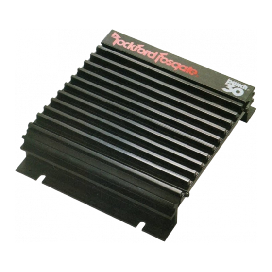
Summary of Contents for Rockford Fosgate PUNCH 30
- Page 1 INSTALLATION MANUAL PUNCH 30 PUNCH 30 PUNCH 45HD PUNCH 45HD PUNCH 75HD PUNCH 75HD PUNCH 150HD PUNCH 150HD...
-
Page 2: Practice Safe Sound
PRACTICE SAFE SOUND™ CONTINUOUS EXPOSURE TO SOUND PRESSURE LEVELS OVER 100dB MAY CAUSE PERMANENT HEARING LOSS. HIGH-POWERED AUTOSOUND SYSTEMS PRODUCE SOUND PRESSURE LEVELS WELL OVER 130dB. USE COMMON SENSE AND PRACTICE SAFE SOUND. Make your t.$ %~&c@Q system complete with installation accessories from , a division of Rockford Corp. -
Page 3: Table Of Contents
TABLE OF CONTENTS INTRODUCTlON ..........................PUNCH EQUALIZER ........................... INPUT CONNECTIONS ........................INPUT LEVEL CONTROLS ..............................................POWER CONNECTlONS FUSE SELECTION ..........................G R O U N D CONNECTlON ........................TURN ON CONNECTION ........................SPEAKER CONNECTlONS ........................ SPEAKER WIRE ..........................SPEAKER IMPEDANCE ........................BRIDGING MODE.. -
Page 4: Introductlon
INTRODUCTION The Rockford Punch 30, Punch 45, Punch 75 and Punch 150 are automotive stereo power amplifiers which will provide state-of-the-art sound in cars, vans, boats, or wherever a 12 volt battery is available. The Punch adjustable input circuits are designed to match almost any music source, from low preamp levels to speaker levels, with negligible noise. -
Page 5: Input Level Controls
INPUT LEVEL CONTROLS The Punch input level controls are accessible with a jeweler’s screwdriver through two holes in the cover. The controls are factory-preset to a level which matches most 500 millivolt to 1 volt rated preamp-output source units. If you are using the speaker - output leads of the source unit, turn the Punch input controls fully counterclockwise to their minimum gain position. -
Page 6: Turn On Connection
“Accessory” or “Auto Antenna” lead, either of which will go positive when the source is turned on. (Note: The Punch 30 is turned on by applying 12 volts to the REM terminal.) Although the majority of high quality automotive source units have an Accessory or Auto Antenna output, there are many which may require different turn-on methods. -
Page 7: Speaker Impedance
SPEAKER IMPEDANCE The Punch is rated for operation into loads of 2 Ohms or greater in stereo operation. The primary loads on the amplifier come from directly connected speakers (not isolated by capacitors), and the measured resistance for each side cannot be less than 1.8-Ohms. Single 4-Ohm woofers or parallel 4-Ohm pairs per side will form a high performance system. -
Page 8: Passive Crossover Impedance
The power rating for speakers should correspond to the rated output of the amplifiers: AMPLIFIER MODE IMPEDANCE POWER Punch 30 Stereo 4-ohm 15 Watts Bridged Mono... -
Page 10: Protection Circuits And Fusing
PUNCH 30 MOSFET PROTECTION AND FUSING The Punch30 is protected by two 3-Ampere speaker-line fuses and by a 7-Ampere battery fuse. A thermal sensor shuts down the amplifier in case of overheating. Internal circuitry shuts down the amplifier in case of overload. -
Page 11: Battery And Charging System
TRUNK MOUNTING We have measured trunk temperatures as high as 175 degrees Fahrenheit in the summertime. Since the thermal shutoff point for the Punch is 195 degrees F, it is easy to see that the amp must be mounted for maximum cooling capability. Mounting the amp on the floor or roof of the trunk will not allow convection air flow. -
Page 12: Punch 3 0 Specifications
26 dBV (correct for most 500 millivolt-rated source units). PROTECTION: The Punch 30 MOSFET is protected by two 3-Ampere speaker-line fuses and by a 7-Ampere battery fuse. A thermal switch shuts down the amplifier in case of overheating. Internal circuitry limits power in case of o v e r l o a d . -
Page 13: Punch 4 5 Specifications
SPECIFICATIONS: PUNCH 45 MOSFET POWER RATINGS: 4-Ohms: 22.5 Watts per channel continuous power, both channels driven into 4 Ohms from 20 to 20,000 Hertz, with less than 0.05% THD+N. (Total Harmonic Distortion plus Noise). 4-Ohms: 40 Watts per channel continuous power, both channels driven into 4 Ohms at 1000 Hertz, with less than 10% THD+N. -
Page 14: Punch 7 5 Specifications
SPECIFICATIONS: PUNCH 75 MOSFET POWER RATINGS: 37.5 Watts per channel continuous power, both channels driven into 4 Ohms from 4-Ohms: 20 to 20,000 Hertz, with less than 0.05% THD+N (Total Harmonic Distortion plus Noise). 4-Ohms: 60 Watts per channel continuous power, both channels driven into 4 Ohms at 1000 Hertz, with less than 10% lHD+N. - Page 15 SPECIFICATIONS: PUNCH 150 MOSFET POWER RATINGS: 4-Ohms: 75 Watts per channel continuous power, both channels driven into 4 Ohms from 20 to 20,000 Hertz, with less than 0.05% THD+N. (Total Harmonic Distortion plus Noise). 4-Ohms: 120 Watts per channel continuous power, both channels driven into 4 Ohms at 1000 Hertz, with less than 10% THD+N.


