Advertisement
Chapter 1
Getting Started
Thank you for choosing the 7667 v2.2 Series (MS-7667)
Micro-ATX mainboard. The series mainboards are based
on Intel
P67 chipsets for optimal system efficiency.
®
Designed to fit the advanced Intel
LGA1155 processor,
®
the series deliver a high performance and professional
desktop platform solution.
Advertisement
Table of Contents

Related Manuals for MSI MS-7667


Summary of Contents for MSI MS-7667
-
Page 1: Getting Started
Chapter 1 Getting Started Thank you for choosing the 7667 v2.2 Series (MS-7667) Micro-ATX mainboard. The series mainboards are based on Intel P67 chipsets for optimal system efficiency. ® Designed to fit the advanced Intel LGA1155 processor, ® the series deliver a high performance and professional desktop platform solution. -
Page 2: Mainboard Specifications
Getting Started Mainboard Specifications Processor Support ■ Intel Sandy Bridge processor in the LGA1155 package ® Chipset ■ Intel P67 chipset ® Memory Support ■ 4 DDR3 DIMMs support DDR3 2133(Over Clocking)/ 1600(Over Clocking)/ 1333/ 1066 DRAM (32GB Max) ■ Supports Dual-Channel mode ■... - Page 3 MS-7667 Connectors/ Ports ■ Back panel 1 Coaxial S/PDIF-Out 1 Optical S/PDIF-Out 1 IEEE 1394 port 6 USB 2.0 ports 1 eSATA port 1 LAN port 6 flexible audio ports ■ On-Board 2 USB 2.0 connector 2 USB 3.0 ports 1 Front Panel Audio connector 1 OC switch /LED connector Slots...
-
Page 4: Mainboard Layout
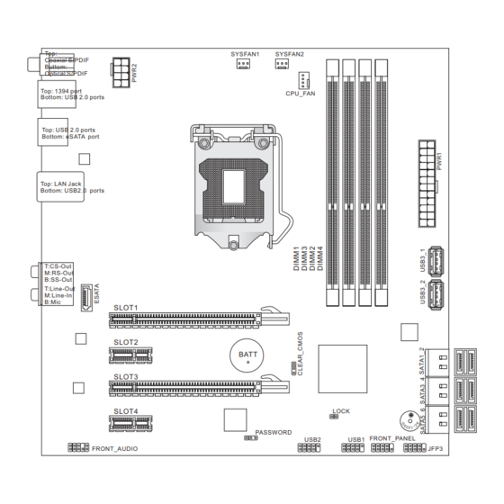
Getting Started Mainboard Layout Top: SYSFAN1 SYSFAN2 Coaxial S/PDIF Buttom: Optical S/PDIF Top: 1394 port CPU_FAN Bottom: USB 2.0 ports Top: USB 2.0 ports Bottom: eSATA port Top: LAN Jack Bottom: USB2.0 ports T:CS-Out M:RS-Out B:SS-Out Line-Out Line-In SLOT1 SLOT2 BATT SLOT3 SLOT4... -
Page 5: Hardware Setup
Chapter 2 Hardware Setup This chapter provides you with the information about hardware setup procedures. While performing the instal- lation, be careful in holding the components and follow- ing the installation procedures. For some components, if you install in the wrong orientation, the components will not work properly. -
Page 6: Quick Components Guide
Hardware Setup Hardware Setup Quick Components Guide PWR2, p.2-10 SYSFAN1/2, p.2-14 DDR3, p.2-8 CPU, p.2-4 CPUFAN, p.2-14 Back Panel, PWR1, p.2-10 p.2-11 USB3_1/2, p.2-15 CLEAR_CMOS, ESATA, p.2-13 p.2-17 SATA1~6, p.2-13 PCIE, p.2-18 JFP3, p.2-16 FRONT_AUDIO, p.2-16 FRONT_PANEL, p.2-14 USB1/ 2, p.2-15 PASSWORD, p.2-17... -
Page 7: Screw Holes
MS-7667 MS-7667 Screw Holes When you install the mainboard, you have to place the mainboard into the chassis in the correct direction. The locations of screws holes on the mainboard are shown as below. The side has to toward the rear, the position for the I/O shield of the chassis. - Page 8 When you are installing the CPU, make sure to install the cooler to prevent overheating. If you do not have the CPU cooler, consult your dealer before turning on the computer. For the latest information about CPU, please visit http://www.msi.com/index. php?func=cpuform2...
-
Page 9: Cpu & Cooler Installation
MS-7667 MS-7667 CPU & Cooler Installation When you are installing the CPU, make sure the CPU has a cooler attached on the top to prevent overheating. Meanwhile, do not forget to apply some thermal paste on CPU before installing the heat sink/cooler fan for better heat dispersion. Follow the steps below to install the CPU &... - Page 10 Hardware Setup Hardware Setup Engage the load lever while pressing Secure the lever near the hook end down lightly onto the load plate. under the retention tab. Make sure the four hooks are in por- Align the holes on the mainboard with per position before you install the the heatsink.
- Page 11 MS-7667 MS-7667 Press the four hooks down to fasten Turn over the mainboard to confirm the cooler. that the clip-ends are correctly in- serted. Mainboard Hook Finally, attach the CPU Fan cable to the CPU fan connector on the main- board.
- Page 12 Hardware Setup Hardware Setup Memory These DIMM slots are used for installing memory modules. For more information on compatible components, please visit http://www.msi.com/index.php?func=testreport DDR3 240-pin, 1.5V 48x2=96 pin 72x2=144 pin Memory Population Rule Please refer to the following illustrations for memory population rules.
-
Page 13: Installing Memory Modules
MS-7667 MS-7667 Installing Memory Modules The memory module has only one notch on the center and will only fit in the right orientation. Insert the memory module vertically into the DIMM slot. Then push it in until the golden finger on the memory module is deeply inserted in the DIMM slot. The plastic clip at each side of the DIMM slot will automatically close when the memory module is properly seated. -
Page 14: Power Supply
Hardware Setup Hardware Setup Power Supply ATX 24-pin Power Connector: PWR1 This connector allows you to connect an ATX 24-pin power supply. To connect the ATX 24-pin power supply, make sure the plug of the power supply is inserted in the proper orientation and the pins are aligned. -
Page 15: Back Panel
MS-7667 MS-7667 Back Panel IEEE 1394 Port Coaxial S/PDIF-Out USB 2.0 Port CS-Out Line-In RS-Out Line-Out USB 2.0 Port eSATA Port USB 2.0 Port SS-Out Optical S/PDIF-Out ▶ Coaxial S/PDIF-Out This S/PDIF (Sony & Philips Digital Interconnect Format) connector is provided for digi- tal audio transmission to external speakers through a coaxial cable. - Page 16 Hardware Setup Hardware Setup ▶ The standard RJ-45 LAN jack is for connection to Yellow Green/ Orange the Local Area Network (LAN). You can connect a network cable to it. Color LED State Condition Left Yellow LAN link is not established. On(Steady state) LAN link is established.
- Page 17 MS-7667 MS-7667 Connectors Serial ATA Connector: SATA1~6 / ESATA This connector is a high-speed Serial ATA interface port. Each connector can connect to one Serial ATA device. * The MB layout in this figure is for reference only. SATA1_2 SATA1~2 (6Gb/s) SATA3_4 SATA3~6 (3Gb/s) SATA5_6...
- Page 18 Hardware Setup Hardware Setup Fan Power Connectors: CPU_FAN,SYSFAN1~2 The fan power connectors support system cooling fan with +12V. When connecting the wire to the connectors, always note that the red wire is the positive and should be con- nected to the +12V; the black wire is Ground and should be connected to GND. If the mainboard has a System Hardware Monitor chipset on-board, you must use a specially designed fan with speed sensor to take advantage of the CPU fan control.
- Page 19 MS-7667 MS-7667 Front USB 2.0 Connector: USB1/ USB2 This connector, compliant with Intel I/O Connectivity Design Guide, is ideal for con- ® necting high-speed USB interface peripherals such as USB HDD, digital cameras, MP3 players, printers, modems and the like. * The MB layout in this figure is for reference only.
- Page 20 Hardware Setup Hardware Setup Front Panel Audio Connector: FRONT_AUDIO This connector allows you to connect the front panel audio and is compliant with Intel ® Front Panel I/O Connectivity Design Guide. OC switch /LED Connector: JFP3 This connector is for electrical connection to the overclocking switch and LED. 2-16...
-
Page 21: Clear Bios Password Jumper
MS-7667 MS-7667 Jumpers Clear CMOS Jumper: CLEAR_CMOS There is a CMOS RAM on board with an external battery power supply to preserve the system configuration data. With the CMOS RAM, the system can automatically boot OS every time it is turned on. If you want to clear the system configuration, set the jumper to clear data. - Page 22 Hardware Setup Slots PCIE (Peripheral Component Interconnect Express) Slot The PCIE slot supports the PCIE interface expansion card. PCIE x16 Slot PCIE x1 Slot 2-18...