Table of Contents
Advertisement
TopPage
CHAPTER 1. BEFORE SERVICING
CHAPTER 2. WARNING TO SERVICE PERSONNEL
CHAPTER 3. PRODUCT SPECIFICATIONS
CHAPTER 4. APPEARANCE VIEW
CHAPTER 5. OPERATION SEQUENCE
CHAPTER 6. FUNCTION OF IMPORTANT COMPO-
NENTS
CHAPTER 7. TROUBLESHOOTING GUIDE
CHAPTER 8. TEST PROCEDURES
SERVICE MANUAL
MICROWAVE OVEN WITH
GRILL AND CONVECTION
MODELS
In interests of user-safety the oven should be restored to its
original condition and only parts identical to those specified
should be used.
CONTENTS
CHAPTER 9. TOUCH CONTROL PANEL ASSEMBLY
CHAPTER 10. PRECAUTIONS FOR USING LEAD-
FREE SOLDER
CHAPTER 11. COMPONENT REPLACEMENT AND
ADJUSTMENT PROCEDURE
CHAPTER 12. MICROWAVE MEASUREMENT
CHAPTER 13. TEST DATA AT A GLANCE
CHAPTER 14. CIRCUIT DIAGRAMS
Parts List
S9614R939PHW/
R-939(BK)
R-939(IN)
R-939(W)
This document has been published to be used for
after sales service only.
The contents are subject to change without notice.
R939(W)
Advertisement
Table of Contents

Related Manuals for Sharp R-939(BK)


Summary of Contents for Sharp R-939(BK)
- Page 1 TopPage R939(W) SERVICE MANUAL S9614R939PHW/ MICROWAVE OVEN WITH GRILL AND CONVECTION R-939(BK) MODELS R-939(IN) R-939(W) In interests of user-safety the oven should be restored to its original condition and only parts identical to those specified should be used. CONTENTS CHAPTER 1. BEFORE SERVICING CHAPTER 9.
-
Page 2: Table Of Contents
CONTENTS CHAPTER 1. BEFORE SERVICING CHAPTER 8. TEST PROCEDURES GENERAL IMPORTANT INFORMA- Procedure A: MAGNETRON TEST .... 8-1 TION ............1-1 Procedure B: HIGH VOLTAGE TRANS- FORMER TEST .......... 8-2 WARNING........... 1-1 CAUTION MICROWAVE RADIATION ... -
Page 3: Chapter 1. Before Servicing
[1] GENERAL IMPORTANT INFORMATION This Manual has been prepared to provide Sharp Corp. Service engineers with Operation and Service Information. It is recommended that service engineers carefully study the entire text of this manual, so they will be qualified to render satisfactory customer ser- vice. -
Page 4: Caution Microwave Radiation
R939(W) [3] CAUTION MICROWAVE RADIATION Personnel should not be exposed to the microwave energy which may radiate from the magnetron or other microwave generating devices if it is improperly used or connected. All input and output microwave connections, waveguides, flanges and gaskets must be secured. -
Page 5: Chapter 2. Warning To Service Personnel
Indien het water nog steeds schroevedraaier kortsluit tegen het chassis. koud is, herhaalt u de allereerste drie stappen en controleer Sharp beveelt ten sterkste aan dat, voor zover mogelijk, nogmaals de aansluitingen naar de geteste onderdelen. defecten worden opgespoord wanneer de stekker uit het Wanneer alle reparaties zijn uitgevoerd en de oven weer in stopcontact is gehaald. - Page 6 R939(W) 2 – 2...
- Page 7 R939(W) 2 – 3...
-
Page 8: Chapter 3. Product Specifications
R939(W) CHAPTER 3. R939(W) PRODUCT SPECIFICATIONS Service Manual DESCRIPTION 230 Volts Power Requirements 50 Hertz Single phase, 3 wire earthed Power Consumption Microwave cooking 1.5 kW Approx 6.7A Convection cooking 2.8 kW Approx 12.2A Grill cooking 2.8 kW Approx 12.2A Dual cooking Micro and Grill ----------------2.80kW Approx 12.4A... -
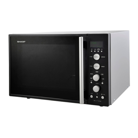
Page 9: Chapter 4. Appearance View Oven
R939(W) CHAPTER 4. R939(W) APPEARANCE VIEW Service Manual [1] OVEN 1. Grill heating element 2. Oven lamp 3. Control panel 4. Shelf runners 5. Waveguide cover 6. Oven cavity 7. Coupling 8. Door seals and sealing surfaces (R-939(BK) only) 9. Door opening handle 10.Air-vent openings 11.Outer cabinet (R-939(BK) only) -
Page 10: Chapter 5. Operation Sequence Off Condition
R939(W) CHAPTER 5. R939(W) OPERATION SEQUENCE Service Manual [1] OFF CONDITION 3. The 2450 MHz microwave energy produced in the magnetron gen- erates a wavelength of 12.24 cm. This energy is channelled Closing the door activates the monitored latch switch and the stop through the waveguide (transport channel) into the oven cavity, switch. -
Page 11: Grill Cooking Condition
R939(W) SETTING; 3. CONVECTION COOKING (by 250°C) Rotate the COOKING MODE dial to the convection setting. And 32 sec. ON enter the cooking time by rotating the TIMER/ WEIGHT dial. And 100% (HIGH) 100% select the desired cooking temperature 250°C by pressing the CON- 24 sec. -
Page 12: On/Off Time Ratio
R939(W) [6] ON/OFF TIME RATIO In dual cooking, the magnetron operate within a 48 second time base. The following table is the ON / OFF time ratio at each power output of the magnetron. POWER OUTPUT ON TIME OFF TIME 100% 48 sec. -
Page 13: Chapter 6. Function Of Important Com
R939(W) CHAPTER 6. R939(W) FUNCTION OF IMPORTANT COMPONENTS Service Manual [1] DOOR OPEN MECHANISM CAUTION: BEFORE REPLACING A NOISE FILTER (BLOWN FUSE F2 F8A), TEST THE MONITORED LATCH SWITCH SW1 The door can be opened by pulling the door handle. AND MONITOR SWITCH SW3 FOR PROPER OPERA- TION. -
Page 14: Noise Filter
R939(W) the asymmetric rectifier is 1.7 KV. D1 and D2 of the asymmetric recti- When the convection time reaches “0”, the heating elements are deen- fier or high voltage rectifier are shorted when the each peak reverse ergized and the convection fan stops operating and the oven shuts off. voltage goes beyond the each rated peak reverse voltage. -
Page 15: Microwave Cooking
R939(W) 1. Microwave Cooking: Damper is in the open position, because a portion of cooling air is channelled through the cavity to remove steam and vapours given off from the heating foods. It is then exhausted at the top of the oven cav- ity into a condensation compartment. -
Page 16: Chapter 7. Troubleshooting Guide Foreword
R939(W) CHAPTER 7. R939(W) TROUBLESHOOTING GUIDE Service Manual [1] FOREWORD When troubleshooting the microwave oven, it is helpful to follow the Sequence of Operation in performing the checks. Many of the possible causes of trouble will require that a specific test be performed. These tests are given a procedure letter which will be found in the “Test Procedure”... -
Page 17: Chart
R939(W) [2] CHART BLOCKED COOLING FAN BLOCKED CONVECTION FAN NO POWER AT WALL OUTLET HOME FUSE OR BREAKER MIS-ADJUSTMENT OF SWITCHES BLOCKED VENTILATION OPENINGS OPENED WIRE HARNESS SHORTED WIRE HARNESS OVEN LAMP OR SOCKET POWER SUPPLY CORD FOIL PATTERN ON P.W.B. RELAY RY8 RELAY RY7 RELAY RY6... -
Page 18: Chapter 8. Test Procedures
R939(W) CHAPTER 8. R939(W) TEST PROCEDURES Service Manual [1] Procedure A: MAGNETRON TEST NEVER TOUCH ANY PART IN THE CIRCUIT WITH YOUR HAND OR AN INSULATED TOOL WHILE THE OVEN IS IN OPERATION. CARRY OUT 3D CHECKS. Isolate the magnetron from the high voltage circuit by removing all leads connected to the filament terminal. To test for an open circuit filament use an ohmmeter to make a continuity test between the magnetron filament terminals, the meter should show a reading of less than 1 ohm. -
Page 19: Procedure B: High Voltage Transformer Test
R939(W) 1000g 1000g 1000g T1 C T2 C Heat up for 50 sec. [2] Procedure B: HIGH VOLTAGE TRANSFORMER TEST WARNING: High voltages and large currents are present at the secondary winding and filament winding of the power transformer. It is very dangerous to work near this part when the oven is on. -
Page 20: Procedure E: Switch Test
R939(W) If incorrect reading are obtained, the high voltage capacitor must be replaced. CARRY OUT 4R CHECKS. [5] Procedure E: SWITCH TEST CARRY OUT 3D CHECKS. Isolate the switch to be tested and using an ohmmeter check between the terminals as described in the following table. Table: Terminal Connection of Switch Plunger Operation Common terminal to Normally open terminal... -
Page 21: Procedure I: Noise Filter Test
R939(W) [9] Procedure I: NOISE FILTER TEST CARRY OUT 3D CHECKS. Disconnect the leads from the terminals of the noise filter. Using an ohmmeter, check between the terminals as described in the following table. MEASURING POINT INDICATION OF OHMMETER Between N and L Approx. -
Page 22: Procedure N: Jog And Switch Unit Test
R939(W) b) When touching the buttons, sometimes a button produces no signal. 2) Potentiometer a) When rotating the potentiometer, the cooking mode can not be selected. 3) Encoder a) When rotating the encoder, the cooking time or the weight of food can not be entered. 2. -
Page 23: Procedure O: Relay Test
R939(W) [15] Procedure O: RELAY TEST CARRY OUT 3D CHECKS. Remove the outer case and check voltage between Pin Nos. 1 and 3 of the 4 pin connector (E) on the control unit with an A.C. voltmeter. The meter should indicate 230 volts, if not check oven circuit. Relay Test Check voltage at the relay coil with a D.C. -
Page 24: Chapter 9. Touch Control Panel Assem
R939(W) CHAPTER 9. R939(W) TOUCH CONTROL PANEL ASSEMBLY Service Manual [1] OUTLINE OF TOUCH CONTROL PANEL The control section consists of the following units as shown in the con- -5.2V LSI(IC1) trol panel circuit. 3) Synchronizing Signal Circuit (1) Jog and Switch Unit The power source synchronizing signal is available in order to com- (2) Control Unit (The Control unit consists of Power unit and CPU unit.) pose a basic standard time in the clock circuit. - Page 25 R939(W) 6) After that procedure, re-connect the power supply cord. After checking the performance of the touch control panel, 1) Disconnect the power supply cord. 2) Open the door and block it open. 3) Re-connect the leads to the primary of the power transformer. 4) Re-install the outer case (cabinet).
-
Page 26: Chapter 10. Precautions For Using Lead
R939(W) CHAPTER 10. R939(W) PRECAUTIONS FOR USING LEAD-FREE SOLDER Service Manual 1. Employing lead-free solder The “Main PWB” of this model employs lead-free solder. This is indicated by the “LF” symbol printed on the PWB and in the service manual. The suffix letter indicates the alloy type of the solder. -
Page 27: Chapter 11. Component Replacement And Adjustment Procedure Before Operating
4) If the outer case (cabinet) is not fitted. 4) The door is bent or warped. WARNING FOR WIRING To prevent an electric shock, take the following manners. 3) Sharp edge: 1. Before wiring, Bottom plate, Oven cavity, Waveguide flange, Chassis support and other metallic plate. -
Page 28: High Voltage Transformer Removal
R939(W) 4. Remove one (1) screw holding earth side terminal of the high volt- 8. Now, the high voltage rectifier assembly and the high voltage age rectifier assembly to the base plate through the capacitor capacitor should be free. holder. CAUTION: WHEN REPLACING HIGH... -
Page 29: Turntable Motor Replacement
Slit 2. REINSTALL 1. Remove the any sharp edges on the turntable motor cover and the base plate with the cutting pliers. 2. Re-install turntable motor by locating shaft onto coupling to the oven cavity base plate with the two (2) screws. -
Page 30: Positive Lock
R939(W) 9. Remove the two (2) screws holding the back plate to the convec- 4. Remove the one (1) screw holding the convection heater angle and tion duct. the air separate angle D to the convection duct. 10.Remove the back plate from the oven cavity. 5. - Page 31 R939(W) 2. Remove the one (1) screw holding the green/yellow wire to the 2. REINSTALL back plate. 1. Insert the moulding cord stopper of power supply cord into the 3. Disconnect the leads of the power supply cord from the noise filter, square hole of the power angle, referring to the Figure C-4(b).
- Page 32 R939(W) The horizontal position of the latch hook should be placed where 4. When the door is closed the contacts (COM-NC) of the monitor the monitor switch has activated with the door closed. The vertical switch and monitored latch switch open. And the contacts (COM- position of the latch hook should be placed where the monitored NO) of their switches close.
- Page 33 R939(W) 5. Hold the door panel to the door frame with eight (8) screws. NOTE: The door on a microwave oven is designed to act as an elec- tronic seal preventing the leakage of microwave energy from 6. Re-install choke cover to door panel by clipping into position. oven cavity during cook cycle.
- Page 34 R939(W) CHAPTER 12. R939(W) MICROWAVE MEASUREMENT Service Manual After adjustment of door latch switches, monitor switch and door are completed individually or collectively, the following leakage test must be per- formed with a survey instrument and it must be confirmed that the result meets the requirements of the performance standard for microwave oven. REQUIREMENT The safety switch must prevent microwave radiation emission in excess of 5mW/cm at any point 5cm or more from external surface of the oven.
- Page 35 R939(W) CHAPTER 13. R939(W) TEST DATA AT A GLANCE Service Manual PARTS SYMBOL VALUE / DATA Fuse 20A 250V Fuse (Noise filter) Thermal cut-out 125°C Off Thermal cut-out TC2, TC3 170°C Off / 155°C On Thermistor Approx. 359.9 kΩ - 152 kΩ at 20°C - 30°C Grill heating element Approx.
- Page 36 R939(W) CHAPTER 14. R939(W) CIRCUIT DIAGRAMS Service Manual [1] Oven Schematic SCHEMATIC NOTE: CONDITION OF OVEN 1. DOOR CLOSED. 2. PLUGGED IN OVEN. 3. NOTHING APPEARS ON DIS PLAY. NOTE: " " indicates components with potentials above 250V CONTROL UNIT SW4: SW2: DAMPER...
- Page 37 R939(W) SCHEMATIC NOTE: CONDITION OF OVEN 1. DOOR CLOSED. 2 " . O" APPEARS ON DISPLAY. NOTE: " " indicates components with potentials above 250V CONTROL UNIT SW4: SW2: DAMPER STOP THERMISTOR SWITCH SWITCH ASYMMETRIC N.O . COM. COM. N.O. RECTIFIER N.C.
- Page 38 R939(W) SCHEMATIC NOTE: CONDITION OF OVEN 1. DOOR CLOSED. 2. GRILL MODE SET. 3. COOKING TIME SET. 4. STRAT BUTTON PRESSED. NOTE: " " indicates components with potentials above 250V CONTROL UNIT DAMPER STOP THERMISTOR SWITCH SWITCH ASYMMETRIC COM. N.O . COM.
- Page 39 R939(W) SCHEMATIC NOTE: CONDITION OF OVEN 1. DOOR CLOSED. 2. DUAL1 MODE SET. 3. COOKING TIME SET. 4. MICROWAVE POWER LEVEL SET. 5. CONVECTION TEMPERATURE SELECTED. 6. STRAT BUTTON PRESSED. NOTE: " " indicates components with potentials above 250V CONTROL UNIT SW4: SW2:...
- Page 40 R939(W) [2] Pictorial Diagram Figure S-1. Pictorial Diagram 14 – 5...
- Page 41 R939(W) [3] Power Unit Circuit OVEN S1NB10 WH1-4 THERMISTOR WH1-3 Ð R4 510 1w WH1-6 Q1 2SB1238 R5 3.3k WH1-9 BUZZER AC230V R3 680 1w 50Hz WH2-2 WH1-10 WH1-5 POWER WH1-11 CONTROL FAN MOTOR WH1-8 CONVECTION WH1-7 MOTOR DAMPER WH2-4 MOTOR R6 130 1w OVEN LAMP...
- Page 42 R939(W) [4] Control Unit Circuit Figure S-3. CPU Unit Circuit 14 – 7...
- Page 43 R939(W) [5] Indicator Circuit Figure S-4. Indicator Circuit 14 – 8...
- Page 44 R939(W) [6] Jog and Switch Unit Circuit CN-J : IF NOT SPECIFIED 0.01uF / 25V or 50V : IF NOT SPECIFIED 1/10W ±5% B13B-PH-K-S SW11 R68 15K IC1-6(P73) SW10 SW12 R69 15K IC1-7(P72) SW13 R70 15K IC1-8(P71) IC1-9(P70) R72 -- R75 C60 -- C63 100K x4 330pF/50V x4...
- Page 45 R939(W) [7] Printed Wiring Board VRS1 POWER CONT Figure S-6. Printed Wiring Board of Power Unit 14 – 10...
- Page 46 R939(W) MEMO [8] Printed Wiring of Board of Switch Unit Figure S-7. Printed Wiring of Board of Switch Unit 14 – 11...
-
Page 47: Parts List
R939(W) PARTS LIST MICROWAVE OVEN WITH GRILL AND CONVECTION HOW TO ORDER REPLACEMENT PARTS To have your order filled promptly and correctly, please R-939(BK) MODELS furnish the following information. 1. MODEL NUMBER R-939(IN) 2. REF. NO. 3. PART NO. 4. DESCRIPTION R-939(W) Parts marked "*"... - Page 48 R939(W) [1] OVEN PARTS 7-16 4-17 7-10 4-25 4-18 4-20 7-17 4-27 7-16 4-10 4-39 4-22 7-16 4-21 4-19 4-13 4-23 4-15 7-17 7-12 4-16 7-16 7-13 4-24 4-14 4-11 7-16 7-11 4-26 7-12 4-30 4-28 7-16 7-16 7-16 4-37 4-38 7-14 7-16...
- Page 49 R939(W) PRICE PART PARTS CODE DESCRIPTION RANK MARK RANK [1] OVEN PARTS ELECTRIC PARTS High voltage capacitor RC-QZA219WRE1 Convection heating element RHET-A269WRZ1 Convection motor RMOTEA415WRZ1 Damper motor RMOTDA269WRZ1 Fuse 20A QFS-BA012WRZZ Fan motor RMOTEA002URE2 Grill heating element RHET-A231WRZ1 Magnetron RV-MZA264WRE1 Oven lamp RLMPTA066WRE1 Monitored latch switch...
- Page 50 R939(W) PRICE PART PARTS CODE DESCRIPTION RANK MARK RANK [1] OVEN PARTS Washer: 4mm x 1.0mm XWSUW40-10000 Screw: 4mm x 25mm XEPS740P25000 Screw : 3mm x 6mm XHPS730P06000 Screw: 4mm x 10mm XJPS740P10X00 7-10 Screw: 4mm x 6mm XHPS740P06000 7-11 XOTWW40P10000 Screw : 4mm x 10mm 7-12...
- Page 51 R939(W) PRICE PART PARTS CODE DESCRIPTION RANK MARK RANK [2] CONTROL PANEL AND DOOR PARTS CONTROL PANEL PARTS CPU unit DPWB-A406DRKZ Power unit DPWBFA226URK0 Switch unit DPWB-A411DRKZ Control panel [R-939(W)] HPNLCC006WRRZ Control panel [R-939(BK)] HPNLCC004WRRZ Control panel [R-939(IN)] HPNLCC003WRRZ Display window GMADIA163WRRZ Key button A [R-939(W)] JBTN-B367WRFZ...
- Page 52 R939(W) INDEX PRICE PART PRICE PART PARTS CODE PARTS CODE RANK MARK RANK RANK MARK RANK NTNT-A040WRE0 1-6-2 [ C ] CDORFA050WRKZ 2-5-1 [ P ] CDORFB049WRKZ 2-5-1 PCOVPA309WRE0 1-4-37 CDORFB051WRKZ 2-5-1 PCUSUA050URE0 1-4-2 [ D ] PCUSUA312WRP0 1-4-1 PDUC-A011URF1 1-4-9 DDORFB260WRKZ 2-5-1-2...