Table of Contents
Advertisement
Advertisement
Table of Contents

Related Manuals for KYMCO Kymco UXV 500i


Summary of Contents for KYMCO Kymco UXV 500i
- Page 1 KWANG YANG MOTOR CO.,LTD.
- Page 2 Battery & EFI Damage Alert CELP indication CELP indication : If flashing or brightness, it indicates that a fault has been detected in the vehicle 's EFI or electrical system. Requires immediate inspection by a KYMCO dealer.
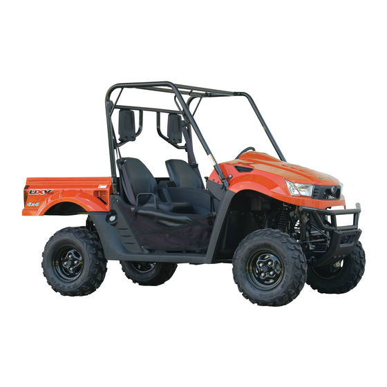
- Page 3 Dear KYMCO UXV 500 i Users: Thank you for purchasing this KYMCO UXV 500i and welcome to the family of KYMCO UXV500 i riders. To enjoy safety and more pleasant riding, become thoroughly familiar with this owner manual before you ride the UXV 500i.
-
Page 4: Table Of Contents
TABLE OF CONTENTS Auxiliary Outlet Differential Lock Lever And Indictor Air Cleaner 74-76 Daily Safety Checks Driving Safety Battery Remove Driving Downhill Brake Fluid Inspection Driving Uphill Back Mirrors Driving Reverse Brake Pedal Emission Control System Cargo Bed 52-54 Engine Oil 67-70 Crossing Water Cooling System Inspection... - Page 5 TABLE OF CONTENTS Operation Instruction for Horn 33-38 Multi-Meter Hazarb Warn Flashers Switch Periodic Maintenance/Lubrication 89-91 Gear Selector Pillows Aduust Parking Brake Release Packing Indicator Lights 31-32 Ignition Switch Right Glove Compartment Key Ignition Switch Key Serial Number Locations Light Switch Start The Engine 59-60 Location Of Parts...
- Page 6 TABLE OF CONTENTS Throttle Pedal Tool Kit Turn Signal Lights Switch Under-Hood 55-56 2WD/4WD Switch Warning Labels Locaton 11-13 Warning Labels (English) 14-21 Warning Labels (French) 22-29 Wheel Removal 80-81...
- Page 7 This vehicle can be dangerous to operate. A impact or rollover can occur quickly. even during routine maneuvers such as turning and driving on hills or over obstacles, if you fail to take proper precautions. For your safety, understand and follow all the warnings contained in this Owner’s Manual and labels on this vehicle.
- Page 8 This vehicle is not a toy and can be dangerous to operate. ●Always go slowly and be extra careful when operating on unfamiliar terrain. Always be alert to changing terrain conditions when operating this vehicle. ●Never operate on too rough, slippery, or loose terrain. ●Always follow proper procedures for turning as represent in this manual.
- Page 9 Safety Watchful Always ● read the owner’s manual carefully and follow the operating procedures described. Pay special attention to the warnings contained In the manual and on all labels. Never ● operate this vehicle with the canopy frame removed. WARNING Always ●...
-
Page 10: Frame Number
Serial Number Locations This vehicle has 2 serial numbers:The frame number and Engine serial number. The frame number is located on the frame near right front wheel place. Frame Number... - Page 11 Serial Number Locations The engine serial number is located on the right side of the engine crankcase. Engine Serial Number...
- Page 12 Ignition Switch Key/Fuel Cap Key Right Glove Compartment Key Fore keys come with this vehicle. Keep the spare in the safe place. Fuel Cap Key Right Glove Compartment Key →2PCS Ignition Switch Key→2PCS...
- Page 13 Location Of Parts (1) 1.Right Head Pillow 2.Right Seat 3.Right Tail /Brake/Turn Light 4.Left Head Pillow 5. Left Seat 6.Left Tail /Brake /Turn Light...
- Page 14 Location Of Parts(2) 07.Seat Belts 08.Cargo Bed 09.Back mirrors 10.Headlights 11.Front Turn Lights 12.Battery 13.Steering Wheel 14.Cab Frame 15.hands Bars 16.Tool or Parts Box (Under the operator’s seat)
- Page 15 Location Of Parts(3) 17.Under-Hood 18.Bumper 19.Hands Bars 20.Seat Belts 21.Fuel Tank Cap 22.Muffler& Spark Arrester 23.Latch Handles...
- Page 16 Location Of Parts(4) 24.Right Glove Compartment 25. Auxiliary Outlet 26.Speedometer 27. Center Glove Compartment 28.Shifting The Automatic Transaxle 29. Ignition Switch 30.Horn31. Steering Wheel 32. Brake Pedal 33.Throttle Pedal...
- Page 17 Warning Labels Location...
- Page 18 Warning Labels Location...
- Page 19 Warning Labels Location...
- Page 20 Warning Labels (English)
- Page 21 Warning Labels (English)
- Page 22 Warning Labels (English)
- Page 23 Warning Labels (English)
- Page 24 Warning Labels (English)
- Page 25 Warning Labels (English)
- Page 26 Warning Labels (English)
- Page 27 Warning Labels (English)
- Page 28 Warning Labels (French)
- Page 29 Warning Labels (French)
- Page 30 Warning Labels (French)
- Page 31 Warning Labels (French)
- Page 32 Warning Labels (French)
- Page 33 Warning Labels (French)
- Page 34 Warning Labels (French)
- Page 35 Warning Labels (French)
-
Page 36: Features And Controls
Features And Controls Fuel Lever Inspection/Refilling Check if fuel is sufficient. If the fuel gauge pointer is E(flash).refill nonleaded gasoline as soon as possible. (Refilling Method) 1.Turn the tank cap counterclockwise with hand to open the cap. 2.Use only nonleaded gasoline. OPEN CLOSE 3.Turn the fuel tank cap clockwise to tighten... -
Page 37: Indicator Lights
Features And Controls Indicator Lights The indicator lights on the console display: 1. Lower Gear 2. High Gear 3.Neutral Gear 4.Reverse Gear 5. Parking Gear 6. Right Turn Signal Indicator Light and Left Turn Signal Indicator Light 7. High Beam Indicator Light 8. FI System Indicator Light 9.Lock:( Differential Lock Indicator Light )10.Battery Low Voltage Indicator Light 11. - Page 38 Features And Controls Instruments and Indicators 1.Speedometer 2. Km/h or Mph 3. Clock 4. 4WD 5.Fuel Gauge 6.ODO Meter 7. Adjust Button 8.Engine Tachometer...
- Page 39 Features And Controls Operation Instruction for Multi-meter Button A (MODE) Button B (SET)
- Page 40 Features And Controls Operation Instruction for Multi-meter Press and hold button A until 2 seconds over. Shift the unit mph or km/h Button A (MODE)
- Page 41 Features And Controls Operation Instruction for Multi-meter Press and hold button B until 2 seconds over. Shift function to ODO or TRIP Button A (SET)
- Page 42 Features And Controls Operation Instruction for Multi-meter Press and hold button A and B until 2 seconds over. Simultaneously to reset to zero when at TRIP function. Button B (SET) Button A (MODE)
- Page 43 Features And Controls Operation Instruction for Multi-meter Press and hold button A and B until 5 seconds over . when at ODO function then you can see clock position is flash word . Button B (SET) Button A (MODE)
- Page 44 Features And Controls Operation Instruction for Multi-meter When you seeing clock position is flash word . You can start setting hour item. Press button B adjust correct hours then Press button A you can see minute position is flash. adjust correct minute. Waiting for 2second .finish times setting.
-
Page 45: Auxiliary Outlet
Features And Controls Auxiliary Outlet The 12-volt receptacle has spade connections on the back that may be used to power an auxiliary light or other optional accessories or lights. The connections are behind the console,under the hood. Auxiliary Outlet... -
Page 46: Seat Removal
Features And Controls Seat Removal • Pull up on front of seat it toward the front of vehicle. • Install the seat by sliding the tabs into the rear of the seat base. • Push down firmly on the front of the pins are fully seated into the grommets. - Page 47 Features And Controls Pillows adjust If you want to adjusting your pillows. Remove 3 bolts then adjusting you need pillow position install 3 bolts.
- Page 48 Features And Controls Gear Selector Maintaining shift linkage adjustment is 1.Lower Gear important to assure proper 2.High Gear transmission function . 3.Neutral Gear See your dealer if you experience any 4.Reverse Gear shifting problems. 5.Parking Gear To change gears,stop the vehicle and with the engine idling, move the lever to the desired gear.
- Page 49 Features And Controls Switches Ignition Switch The ignition switch is a three-position,key- operated switch, The key can be removed from the switch when it is in the OFF position. Electrical circuits are on Electrical equipment can be used. OFF: Engine off .All electrical circuits are off except Acc.12V START: Electrical starter is engaged by holding ignition switch key in this...
- Page 50 Features And Controls Switches Light Switch • The ignition switch key must be in the ON position to operate the headlights. • The switch has 4 positions. 1:Light off -At this position , light is turn off. 2: Position light - At this position , light is turn off 3.LO Headlight Beam- When you select this position .
- Page 51 Features And Controls Switches Drive Select Switch The 2WD/4WD allows the operator to operate the vehicle in either two-wheel drive (rear wheel) or four wheel drive(all wheels) For normal riding on flat,dry,hard surfaces, two-wheels drive should be sufficient. In situations when additional traction is necessary,for-wheel drive would be the desired choice.
-
Page 52: Differential Lock Lever/Indicator
Features And Controls Differential Lock lever and indicator The front axle is equipped with a lockable differential that allows the operator to choose between an open differential or a closed differential in low traction situations. Pulling the lock lever up. To lock the differential on the 4WD, move the 4WD differential Button. - Page 53 Features And Controls Switches Turn Signal Lights Switch When you want direction change just raise or lower the lever the lever until the green arrow starts to flash.hold it there until you complete your direction change . A green arrow on the instrument panel will flash in the direction of the turn or lane change.
- Page 54 Features And Controls Switches Hazard Warn Flashers Switch Your hazard warn flashers let you warn others.They also let police know you have a problem. Your front and rear turn signal lights will flash on and off. Pressing the switch .Turn signal lights will flash on the meter.
-
Page 55: Back Mirrors
Features And Controls Back Mirrors Switches Your back mirrors is convex.A convex Horn mirror’s surface is curved so you can see You can sound born by pressing the more from the seat. born symbols on your steering wheel Back Mirrors Horn... - Page 56 Features And Controls Brake Pedal(1) Depress the brake pedal to slow or stop or stop the vehicle. Throttle Pedal(2) Push the pedal down to increase engine speed .Spring pressure returns the pedal to the rest position when released. Always check that the throttle pedal returns normally before starting the engine.
- Page 57 Features And Controls Parking Brake Release(3) To release the parking brake, pull the release handle Spring pressure helps return the lever to the released position .make sure the parking brake lever is functioning properly before each operation.
- Page 58 Features And Controls Cargo Bed (Lift and lower the cargo bed) To lift Push the cargo bed release lever to right side, then slowly lift up cargo bed until it stop. To lower Lower the cargo bed slowly to its original position and be sure the it is locked into place.
- Page 59 Features And Controls Cargo Bed(Open and close the tailgate 1) To open---(1) Unlock the latches,and then lower the tailgate. Latch(x2) Pull...
- Page 60 Features And Controls Cargo Bed(Open and close the tailgate 2) To close Place the tailgate in the original position ,and then hook the latches.
- Page 61 Features And Controls Under-Hood (To Open) Unhook the hood latches and then slowly tilt the hood up until it stop. Latch x2...
- Page 62 Features And Controls Under-Hood (To Close) Lower the hood slowly to its original position and then hook the hood latches . Latch x2...
-
Page 63: Daily Safety Checks
How to operate Daily Safety Checks Check the following items each day before operation. 01.Fuel---------------------Enough fuel in tank,no leaks. 02.Engine Oil-------------Oil lever between lever holes(when engine is cold),no leaks. 03.Air Cleaner------------Check the restriction gauge. 04.Tires --------------------Air pressure(when cold)and check tires cracks, damage or abnormal wear.Check for any imbedded stones or other foreign particles in tread. - Page 64 How to operate Driving Safely(Driving procedures) 1.Sit in the driver’s seat and fasten the seat belt. 2.After staring the engine and allowing it to warm up,shift the transmission into gear. 3.Check your surroundings and determine your path of travel. 4.Release the parking brake. 5.Keeping both hands on the steering wheel, slowly depress the throttle with your right foot and begin driving.Vehicle speed is controlled by the amount of throttle opening &...
-
Page 65: Start The Engine
How to operate Start the Engine WARNING Never run the vehicle in a closed area, such as a garage Exhaust gases contain carbon monoxide, a colorless, odorless, poisonous gas. Breathing exhaust gas leads to carbon monoxide poisoning, asphyxiation, and death. 1.Wear the seat belts(both operator and passenger) 2.Set the parking brake. - Page 66 How to operate Start the Engine CAUTION Do not run the starting attempt. The starter motor may overheat causing severe starter motor damage. Allow 15 seconds between starting attempts to allow the starter motor to cool. Braking/Stopping Always allow plenty of room and time to stop smoothly. Sometimes quick stops are inevitable’...
-
Page 67: Driving Downhill
How to operate Parking Parking involves flowing the previous rules for braking;then : 1.After the vehicle stops,shift into neutral gear. 2.Set the parking brake. 3.Turn off the ignition key. 4.If you have to park on the hill,shift to low range,set the parking brake,and block the wheel on the downhill side. -
Page 68: Driving Uphill
How to operate Driving Uphill whenever travel straight uphill, follow these precautions: 1.Always travel straight uphill. 2.Avoid steep hills(15° maximum) 3.Keep both feet on the floor. 4.Proceed at a steady rate of speed and throttle opening. NEVER OPERATE UP OR DOWN HILLS STEEPER THAN 15°... -
Page 69: Crossing Water
How to operate Crossing Water UXV500i can only operate in water up to its floorboard.Stay away from fast moving rivers. This vehicle’s tires can be buoyant.In deep water,the vehicle may lose traction due to floating. 1.Physically check the depth and current of the water, especially if you can not see the bottom.Also,check for boulders,logs,or any other hidden obstacles. -
Page 70: Driving In Reverse
How to operate Driving in Reverse Follow these guidelines when operating in reverse: 1.Back slowly. 2.Apply the brakes lightly for stopping. 3.Avoid turning at sharp angles. 4.Always avoid backing downhill. 5.Never open the throttle suddenly while backing. 6. Always inspect left and right fields of vision before backing. -
Page 71: Emission Control System
Emission Control System Crankcase Emission Control System This engine is equipped with a closed crankcase system . Blow-by gases forced back to the combustion chamber by the intake system. The system does not allow the blow-by gases to enter the atmosphere. Exhaust Emission Control System The emissions from the exhaust of this vehicle are controlled by engine design,including factory-set fuel delivery and ignition.KYMCO Exhaust... - Page 72 Emission Control System Spark Arrester Your UXV 500i has a spark arrester. The spark arrester be installed and functional when the vehicle operated on public lands. Clean method Remove method Use the iron brush cleaning remove 3 bolts carbon on the spark arrester...
-
Page 73: Engine Oil
Maintenance And Lubrication Engine Oil Always check and change the oil at the OWNER MANUAL standard intervals. The oil tank is located under the seat. 110 F 1.Position the vehicle on the surface. 2.Start the engine and let it idle for 20~30seconds. 3.Stop the engine and remove the seat. - Page 74 Maintenance And Lubrication Engine Oil 1.Engine oil level measurement A. Place the machine on a level place. B. Warm up the engine for several minutes and stop it. C. Check the oil level through the inspection window. D. The oil level should be between the maximum (H) and minimum (L) marks. If the level is low, add oil to raise it to the proper level.
- Page 75 Maintenance And Lubrication (2) oil drain bolt Engine oil replacement and oil filter cleaning 1. Place the machine on a level place. 2. Warm up the engine for several minutes and stop it. 3. Place a container under the engine. 4.
- Page 76 Maintenance And Lubrication NOTE: Skip steps E to I if the oil filter cartridge is not being replaced. Remove the oil filter cartridge with an oil cartridge wrench. oil filter cartridge remove lock...
-
Page 77: Changing The Rear Gear Box Oil
Maintenance And Lubrication Changing the rear gear box oil Recommended oil : SAE 80 Oil quantity : 1. Place the vehicle on the a level surface. Periodic oil change 2. Place a container under the rear gear box 0.25ML to collect the used oil. 3.Remove the rear gear box oil drain bolt(1) and rear gear box oil filler cap (2). -
Page 78: Changing The Front Gear Box Oil
Maintenance And Lubrication Changing the front gear box oil 1. Place the vehicle on the a level surface. 2. Place a container under the front gear box to collect the used oil. 3.Remove the front gear box oil drain bolt(1) and front gear box oil filler bolt (2). - Page 79 Maintenance And Lubrication BRAKE FLUID INSPECTION Check if the fluid level is below the lower level mark through the inspection window. WARNING POTENTIAL HAZARD Brake fluid contacting the skink or eyes. WHAT CAN HAPPEN May cause irritation. HOW TO AVOID THE HAZARD Avoid contacting brake fluid with the skin or eyes.
- Page 80 Maintenance And Lubrication Air Cleaner Remove the center cover screws. Remove gear selector bolt and center cover.
- Page 81 Maintenance And Lubrication Air Cleaner Remove air cleaner cover screws and air filter element fixed bolt . Remove air filter element.
- Page 82 Maintenance And Lubrication Air Cleaner Using high pressure air to clean air filter element . Inspect the air filter element and replace it if damaged.
-
Page 83: Battery Remove
Maintenance And Lubrication Battery Remove 1. Make sure the ignition switch is OFF. 2. Remove the under-hood hook& pu bolts. 3. Remove the battery cover screws. 4. Disconnect the negative ( ) terminal lead (1) from the battery first, then disconnect the positive (+) terminal lead (2). -
Page 84: Fuse Replacement
Maintenance And Lubrication Fuse Replacement (1) (2) (3) (4) (5) (6) The fuse box stored in the battery compartment. To replace a fuse: 1. Make sure the ignition switch is OFF. 2. Remove the under-hood hook& pu bolts. 3. Open the fuse box cap. 4. - Page 85 Maintenance And Lubrication Cooling System Inspection NOTE: A permanent type of antifreeze is installed in the 1. Remove the under-hood hook& pu bolts. cooling system when shipped.It is colored green 2. Check the coolant level in the coolant and contains ethylene glycol.It is mixed.It is mixed reservoir when the engine is cold as the at 50% with water and has a freezing point of coolant level will vary with engine...
-
Page 86: Wheel Installation
Maintenance And Lubrication Wheel Installation Wheel Removal When reinstalling a wheel, tighten the wheel nuts in 1.Elevate the wheel by placing a suitable a crisscross(rather than a circular)pattern. stand under the frame. Be sure the tapered a side of the wheel nuts(1)face 2.Remove the nuts from the wheel. - Page 87 Maintenance And Lubrication NOTE: WARNING The arrow mark on the tire must point POTENTIAL HAZARD toward the rotating direction of the wheel. Installing wheels improperly. WHAT CAN HAPPEN A wheel may come loose, possibly leading to an accident. HOW TO AVOID THE HAZARD Carefully follow the instructions in this Owner's Manual when installing.
-
Page 88: Spark Plug Inspection
Maintenance And Lubrication Spark Plug Inspection Before installing the spark plug, measure the The spark plug is an important engine electrode gap with a feeler gauge and adjust to component and is easy to inspect. specification. The condition of the spark plug can indicate the condition of the engine. -
Page 89: Tool Kit
Maintenance And Lubrication Tool Kit The tool kit put down location at Right Glove Compartment . The tool kit includes the following items: (1) Hexagon wrench (3) (5) (1) (2) (2) Spark plug wrench (3) 8/12;10/14;17/19 mm wrench (4) Screwdriver (5) Screwdriver handle (6) Tool bag (7)Air pressure gauge... -
Page 90: Specifications
Specifications MODEL UXV500 i (ON ROAD) DIMENSIONS: OVERALL LENGTH 2870mm OVERALL WIDTH 1500mm OVERALL HEIGHT 1850mm SEAT HEIGHT 805mm WHEELBASE 1910mm GROUND CLEARANCE 310mm MINMUN. TURNING RADIUS 4060mm BASIC WEIGHT: WITH OIL AND FULL FUEL TANK 560kg MAX. CARGO BED LOAD 200kg DRY WEIGHT 525kg... - Page 91 Specifications MODEL UXV500 i (ON ROAD) ENGINE GEAR BOX: CAPICITY/EXCHANGE/TYPE 3.6L/3.0L/5W-30 FRONT GEAR BOX: CAPICITY/EXCHANGE/TYPE 270ML/270ML/SAE80# REAR GEAR BOX CAPICITY/EXCHANGE/TYPE 250ML/250ML/SAE80# AIR FILTER: SPONGE ELEMENT FUEL: TYPE UNLEADED GASOLINE FUEL TANK CAPACITY THROTTLE BODY: TYPE/MANUFACTURER PTA1/KYMCO SPARK PLUG: TYPE/MANUFACTURER CR7E-NGK SPARK PLUG 0.6~0.7mm CLUTH TYPE:...
- Page 92 Specifications MODEL UXV500 i (ON ROAD) TRANSMISSION: V-BELT PRIMARY REDUCTION SYSTEM SECONDARY REDUCTION SYSTEM SHAFT DRIVE TRANSMISSION TYPE: V-BELT AUTOMATIC TIRE: TYPE TUBELESS SIZE(FRONT) 25x 8-12 SIZE(REAR) 25x10-12 WHEEL MATERIAL STEEL PRESSURE FR/RR 0.7/0.98(kgf/cm2) OR 10/14 psi BRAKES: SYSTEM FRONT AND REAR UNIFIED TYPE(FRONT) DUAL DISC BRAKE TYPE(REAR)
- Page 93 Specifications UXV500 i ( ON ROAD) MODEL WHEEL TRAVEL: FRONT WHEEL TRAVEL 190mm REAR WHEEL TRAVEL 190mm ELETRICAL: IGNITION SYSTEM DC, ECU AUTOMATIC CONTROL GENERATOR SYSTEM A.C.MAGNETO BATTERY TYPE MF-VTX20L BATTERY CAPACITY 12V18AH HAEDLIGHT TYPE: BULB VOLTAGE WATTAGE X QUANTITY: HAEDLIGHT: 12V35/35W*2 NO.PLATE LIGHT...
- Page 94 Specifications MODEL UXV500 i (ON ROAD) SPECIFIED FUSES: MAIN FUSE FAN MOTER IGNITION LIGHT DC12VPOWER SPARE SPARE...
- Page 98 Maintenance Record...
- Page 99 Maintenance Record...
- Page 100 Maintenance Record...
- Page 101 Maintenance Record...
- Page 102 By KWANG YANG Motor Co., Ltd. First Edition, JUN 2010 All rights reserved. Any reproduction or unauthorized use without the written permission of KWANG YANG Motor Co., Ltd. is expressly prohibited. T200 -UBA0AD -IT-A1...
- Page 103 KWANG YANG MOTER CO .,LTD NO.35 Wan Hsing Street,San Min District Kaohsiung, Taiwan, Republic Of China Telephone : 886-7-3822526 Fax : 886-7-3950021 Printed in Taiwan...