Table of Contents
Advertisement
•Installation •Operation •Maintenance
This air conditioner design has been certified by the Canadian
Standards Association for installation in recreation vehicles.
SERVICE CALLS & QUESTIONS
Location and phone numbers of qualified Service Centers can
be found at our website http:/www.atwoodmobile.com or call
866-869-3116 to locate a Service Center.
WARNING
It is important that this installation
:
manual is read and understood before
installation. The unit must be installed by a
qualified service technician. Failure to properly
install the unit or attempting to modify it in any
way can be extremely hazardous and may
result in property damage and personal injury
and will void the warranty.
BEFORE INSTALLATION
Ensure that the installation instructions have been
properly read and understood.
Installation must conform to Local wiring codes and
regulations or, in the absence of local codes, the
Standard on Recreational Vehicles, NFPA 1192. and
National Electrical Code NFPA 70.
DO NOT attempt to modify or add components to the
installation procedure.
This equipment must only be serviced by a licensed
refrigeration mechanic to maintain warranty
coverage.
If your installation varies from the method outlined
please contact Atwood Mobile Products, LLC for specialty
advice.
Atwood will not be held responsible for problems
relating to incorrect or improper installation
methods.
AC IOM DUCTED 12/03/2014 rev 8
574-206-9713
GENERAL INFORMATION
I. PURPOSE
This Atwood AirCommand air conditioning unit is
designed for installation on the roof of a recreational
vehicle to provide cooling with AC1361 models and
cooling/heating with AC1511 models.
-The roof must be capable of supporting the weight of the
unit which is 86lbs (39Kg).
-The absolute minimum thickness of the roof must not
be less than 1 inch (25mm).
-Roof thicknesses between 5.0–6.5 inches (125 -165mm)
require extra-long hold-down bolts Atwood PN 15086.
-Trimming of the ductwork and/or bolts may be
necessary depending on the roof thickness.
It is important that the unit is installed properly
and according to the recommended guidelines.
II. ENSURING EFFECTIVE OPERATION
The effectiveness of the air conditioner is dependent on
several factors e.g. size and heat load of the vehicle. When
an Atwood unit is installed Atwood assumes that the
vehicle is well insulated with 1 inch (25mm) foam minimum
in all walls and roof, that the windows are of moderate size
(preferably double glazed) and the roof vents are airtight
when closed. Other methods of reducing heat load include:
-Closing all doors, hatches, windows and blinds
-Position the vehicle so if porch is used, it will face the sun
and protect the windows from direct radiation.
-Turning off appliances that might increase the heat load
-Ensuring the vehicle is parked in a shaded position.
In periods of extreme high temperature it is recommended
to start the air conditioner earlier in the morning to greatly
improve its ability to cope with the expected high heat load.
III. CONDENSATION
In areas of high humidity, the humid air within the RV will
cause "sweating" or condensation in parts of the unit as the
humid warm air contacts the colder air discharge system. If
this occurs please ensure the following:
-Closing all doors, hatches, windows and blinds to limit the
ingress of warm humid air
- Avoid running the inside fan on LOW or AUTO in such
conditions. Running the fan on HI fan speed will result in
higher airflow and reduce the tendency to have
condensation form.
1
LITERATURE NUMBER MPD 15078
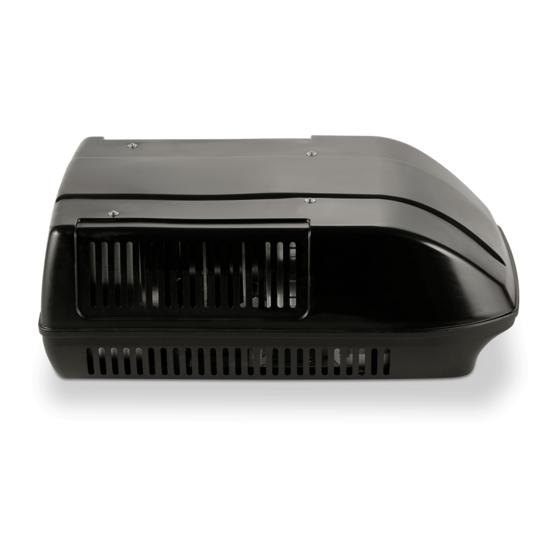
Rooftop Air Conditioner
for Recreational Vehicles
Ducted Models
AC-1361 & AC-1511
Effective 12/03/2014
Advertisement
Table of Contents

Related Manuals for Atwood AC-1361


Summary of Contents for Atwood AC-1361
-
Page 1: General Information
The effectiveness of the air conditioner is dependent on and will void the warranty. several factors e.g. size and heat load of the vehicle. When an Atwood unit is installed Atwood assumes that the vehicle is well insulated with 1 inch (25mm) foam minimum BEFORE INSTALLATION... - Page 2 Installation Guide – Ducted Atwood Air Command Exploded view of Installation Parts 1. Air Command Cormorant Rooftop Air Conditioner 2. Polystyrene baffle x 1 3. Plenum deck assembly x 1 4. Hold down bars x 4 5. Filter x 1 6.
-
Page 3: Installation Position
- If the roof does not have an existing hole one must be cut. Cut from the Atwood would recommend 2 or more units to cool roof then use the roof hole as a guide to cut through the ceiling. Contact effectively. - Page 4 Fig 6- Preferred Method: Gently set the unit over the roof gasket which is attached and sealed to the roof. .79 MIN Fig 6a- An Alternate Method: First attach and seal the roof gasket to the bottom of the roof unit and then gently set unit over the hole in the roof.
-
Page 5: Interconnection Cables
This is a multi-conductor cable which connects the wall mounted thermostat to the rooftop unit. This connection can be made with Atwood PN 15073 or alternatively with a customer supplied cable assembly for which the customer assumes the warranty responsibility for the connections. - Page 6 Blue wire from rooftop unit to White wire from customer – AC Common Yellow/Green wire from rooftop unit to Green wire from customer – Ground Note: Atwood recommends the use of the Molex connector 19421-0001 (Atwood PN 15024) described on the next page. WARNING Ensure that power is properly disconnected at the supply (mains and/or battery).
- Page 7 AC IOM DUCTED 12/03/2014 rev 8...
- Page 8 AC IOM DUCTED 12/03/2014 rev 8...
- Page 9 Installation procedure for Ducted Models 1. Before installing the rooftop unit, be sure that the communication cable (supplied by Atwood) is installed between the wall mounted thermostat location and the rooftop unit. 2. Remove self-adhesive backing from roof sealing gasket (11) and place around mounting hole. Apply a modest amount of silicone sealant around the perimeter of the gasket.
- Page 10 Installation procedure for Ducted Models (continued) 7. Assemble the hold down bars (4) onto the hold down bolts (6). Raise the plenum deck assembly towards the installation hole. Screw the hold down bolts (6) into the inserts on the base of the unit. Tighten bolts until firm, but do not exceed 6 Nm (4.4 foot-pounds).
- Page 11 Installation procedure for Ducted Models (continued) 8. Attach plenum fascia (7) to plenum deck assembly (3) and caravan/RV ceiling with the six button head screws (8) or user-provided wood screws. Cover the screw heads with the cover plugs (9). AC IOM DUCTED 12/03/2014 rev 8...
-
Page 12: Verifying Normal Operation
Replacement filters can be ordered directly from Atwood Mobile Products, LLC by calling 866-869-3118. II. Mounting Bolts Atwood suggests that the hold down bolts are initially checked for tightness within the first 3 months of installation, and thereafter every 12 months if the vehicle is in constant use. -
Page 13: Operating Instructions
5 seconds and the room temperature will be displayed. After Wall mounted Thermostat control. An AC only model releasing the SLEEP pushbutton the display will revert back to (AC-1361) will not have the furnace pushbutton on the displaying the set point temperature. wall pad unit. -
Page 14: Display Setting
DISPLAY SETTING - To change readout from Celsius to Fahrenheit or vice versa: Press Temp Down pushbutton simultaneously with the Fan pushbutton. REMOTE CONTROL UNIT Many models have a remote control unit which can adjust the thermostat remotely. The remote control has duplicated the thermostat input pushbuttons including: the ON/OFF pushbutton, TEMP UP/DOWN, FAN, MODE, SLEEP, and TIMER pushbuttons LEDs in the thermostat control respond to a pushbutton actuation from the remote control unit in the same manner as it would respond to the pushbutton actuation on the thermostat control. - Page 15 OPERATING INSTRUCTIONS FOR ADJUSTING THE THERMOSTAT (cont.) Temperature setting (continued) SLEEP To display the room temperature, press button for 5sec or longer. While this button is depressed, the room temperature is displayed until the key is released. Given the lack of display characters - if the control is displaying temperature in Fahrenheit, temperatures of 100-109°F will be displayed as A0 –A9, temperatures between 110-119°F will be displayed as B0-B9, temperatures between 120-129°F will be displayed as C0-C9, temperatures between 130-139°F will be displayed as D0-D9, temperatures between 140-149°F...
- Page 16 OPERATING INSTRUCTIONS FOR ADJUSTING THE THERMOSTAT (cont) On/Off timer setting When the system is on, setting the timer will turn off the unit after the programmed hours were counted down. When the system is off, setting the timer will turn on the unit after the programmed hours were counted down. TIMER ...
-
Page 17: General Specifications
GENERAL SPECIFICATIONS Air – Conditioner Height - 12.8 inch (325mm) Width – 26.6 inch (675mm) AC Description Model Number 13.5K Ducted AC – White Length - 38.4 inch ( 975mm) AC-1361W Weight – 84-86lb (38-39kg) 13.5K Ducted AC – Black AC-1361B 15K Ducted AC –... -
Page 18: Troubleshooting
TROUBLESHOOTING Control Pad will not illuminate when ON/OFF - Check circuit breaker is on button is pressed - Control cable may be unplugged between outside unit and inside fascia - Check power supply to vehicle - Check circuit breaker is on Unit does not cool - Control cable may be unplugged between outside unit and inside fascia... - Page 19 This warranty extends to the original owner of the product only and is subject to the following conditions: 1. For a period of two years from the date of purchase, Atwood will replace the complete air conditioner if the coils and plumbing leaks due to corrosion. This warranty includes reasonable labor charges required to replace the complete air conditioner.
- Page 20 AC IOM DUCTED 12/03/2014 rev 8...