Table of Contents
Advertisement
Quick Links
SERVICE
ELECTRONIC CASH REGISTER
ELECTRONIC CASH REGISTER
ER-150
Manual
1.
Precaution Statements
2.
Product Specifications
3.
Installation and Operation
4.
Assembly and Disassembly
5.
Exploded View and Part List
6.
PCB Layout and Part List
7.
Block diagram
8.
Wiring Diagram
9.
Schematic Diagrams
C O N T E N T S
Advertisement
Table of Contents

Related Manuals for Sam4s ER-150


Summary of Contents for Sam4s ER-150
- Page 1 ELECTRONIC CASH REGISTER ER-150 SERVICE Manual ELECTRONIC CASH REGISTER C O N T E N T S Precaution Statements Product Specifications Installation and Operation Assembly and Disassembly Exploded View and Part List PCB Layout and Part List Block diagram Wiring Diagram...
- Page 3 Overview of this ECR This service manual provides the technical information for many individual component systems, circuits and gives an analysis of the operations performed by the circuits. If you need more technical information, please contact our service branch or R&D center. Schematics and specifications provide the needed information for the accurate troubleshooting. All information in this manual is subject to change without prior notice.
- Page 4 About this Manual This service manual describes how to perform hardware service maintenance for the SAM4S ER-150 Electronic Cash Register. Notes Notes may appear anywhere in the manual. They describe additional information about the item. Precaution symbols . Indicates a Safety Precaution that applies to this part component.
- Page 5 This manual may not, in whole or in part, be copied, photocopied, reproduced, translated or converted to any electronic or machine readable from without prior written permission of Shin Heung Precision . SAM4S ER-150 Service Manual First edition. March 2004. V1.0 Printed in KOREA...
-
Page 6: Precaution Statements
Remplacer uniquement avec une batterie du même type recommended by the manufacturer. ou d’un type équivalent recommandé par le constructeur. Dispose used batteries according to the manufacturer’s Mettre au rebut les batteries usagées conformément aux instructions. instructions du fabricant. SAM4S ER-150... -
Page 7: Servicing Precautions
5. Use only a grounded-tip soldering iron when soldering or unsoldering ESDs. 6. Use only an anti-static solder removal device. Many solder removal devices are not rated as anti-static; these can accumulate sufficient electrical charge to damage ESDs. SAM4S ER-150... -
Page 8: Product Specifications
Key Board 26 Keys 4C3B,4C4B Drawer Weight : 3.3kg Millimeters Dimensions : 420(L) x 325(W) x 95(H) Weight : 5.6kg Millimeters Dimensions : 420(L) x 325(W) x 225(H) ※ Equipment specifications and design are subject to change without notice. SAM4S ER-150... -
Page 9: Printer Specifications
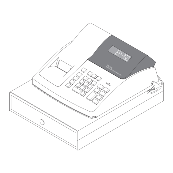
Jumper Wire connection Printer Side Guaranteed Operating 0℃ ~ 50℃ Temperature Reliability (MCBF) 700,00 columns Overall Dimensions 86mm (W) x 50mm(D) x 19mm (H) Weight Approx. 90g ※ Equipment specifications and design are subject to change without notice. SAM4S ER-150... - Page 10 2 Product Specifications 2-2 Appearance 2-2 A. Appearance Dimensions (mm) 2-2 B. ECR Features ① Cover Printer ② Key Board ③ Drawer ④ Window display ⑤ Case Upper ⑥ Power Cord SAM4S ER-150...
- Page 11 2 Product Specifications Memo SAM4S ER-150...
-
Page 12: Installation And Operation
System Reset must be performed before operation. Plug in, while pressing the and 00 keys in 3 seconds at P mode. Then, ER-150 system will be reset and all data will be cleared. -
Page 13: Operation
X-level report generation Z-level report generation Program mode Table 3-1 ECR Modes Figure 3-1 Mode Key Switch 3-2 B. Keyboard Matrix The ER-150 ECR offers keyboard, 26-key, as shown in Table 3-2. Model Keys Type ER-150 Rubber Table 3-2 Keyboard Types... -
Page 14: Assembly And Disassembly
4 Assembly and Disassembly This chapter describes the Disassembling and Reassembling procedures for ER-150, Electronic Cash Register. WARNING: This ECR contains electro-statically sensitive devices. Use caution when handling any components in this system. 4-1 Disassembly CAUTION: Disconnect the ECR from the external power source before Disassembly. The following directions are given for the ER-150. - Page 15 4 Assembly and Disassembly Memo SAM4S ER-150...
-
Page 16: Exploded View And Parts List
5 Exploded View and Parts List Figure5-1 Total Disassembly SAM4S ER-150... - Page 17 5 Exploded View and Parts List Figure5-2 A. ASS’Y COVER-PRINTER A. ASS’Y COVER PRINTER Parts-No. Description/Specification Q'ty Design-Location Serviceable Remark JK97-00924A MEA COVER-PRINT:ER-150,BASIC,WORLD JK70-10320A IPR-CUTTER PAPER:ER-150,STS304,T0.3 JK72-40928B PMO-COVER PRINTER:ER-150,SAM4S SAM4S ER-150...
- Page 18 5 Exploded View and Parts List Figure5-3 B. ASS’Y-PRINTER SAM4S ER-150...
- Page 19 (1017209) JK81-11032A AS-CARRIAGE F/GEAR (F801211020) JK81-11033A AS-PLATEN ASSY (1024287) JK81-11034A AS-JUMPER WIRE (1018148) JK81-11035A AS-PLAIN WASHER (F817210010) JK81-11036A AS-S/PAWL SPR HOLDER (F818202020) JK81-11037A AS-CUP SCREW (B040351111) Note: ( ) means the Printer Manufacture’s Parts List (EPSON’s Parts List) SAM4S ER-150...
- Page 20 5 Exploded View and Parts List Figure5-4 C. ASS’Y CASE-UPPER SAM4S ER-150...
- Page 21 5 Exploded View and Parts List C. ASS’Y CASE-UPPER Parts-No. Description/Specification Q'ty Design-Location Serviceable Remark JK72-40929A PMO-WINDOW DISPLAY:ER-150,PC JK72-40266A PMO-PULLEY WINDING JK72-40931A PMO-CASE BATTERY JK70-10325A IPR-PLATE BATTERY/A: STS304 JK70-10326A IPR-PLATE BATTERY/B: STS304 JK72-40930A PMO-GUIDE PAPER JK39-40302Z CBF HARNESS:,-,UL 1015,290,GRN 6003-001149...
- Page 22 JK75-00020A MEC DRAWER:B43LC(4BILL,3COIN,LOCK) JK75-00022A MEC DRAWER:B43NC(4BILL,3COIN,NO-LOCK) JK75-00023A MEC DRAWER:B43LC(4BILL,4COIN,LOCK) JK75-00024A MEC DRAWER:B44NC(4BILL,4COIN,NO-LOCK) 6003-000221 SCREW-TAPTITE:PWH,+,S,M4,L8,ZPC(YEL) DRAWER+POWER-TRANS JK26-30104C TRANS POWER:ER-150,110/60Hz JK26-30104D TRANS POWER:ER-150,220/50Hz JK72-40345A PMO-BUSHING DRAWER 6002-000175 SCREW-TAPPING:PWH,+,2,M3,L8,ZPC(YEL) PRINT GND + DRAWER 6006-000199 SCREW-ASS'Y TAPT:WT,BH,+,M4,L8,ZPC(YEL) G/PLATE + P/CORD GND WIRE 6003-000168 SCREW-TAPTITE:PH,+,B,M3,L8,ZPC(YEL)
- Page 23 5 Exploded View and Parts List Figure5-6 DRAWER EXPLODED VIEW A. ASS’Y COVER Parts-No. Description/Specification Q'ty Design-Location Serviceable Remark JK70-10406A IPR-HOUSING DRAWER JK72-40375B PMO-COVER BOTTOM 6021-000225 NUT-HEXAGON; 2C,M6,ZPC(YEL),SM20C 6031-000243 WASHER-PLAIN; M5,ID5.3,OD10,T1,ZPC(YEL) JK75-10386A MEC-ROLLER; DRAWER,DR-19-B1/PI19 JK61-40201A FOOT; B-DRAWER,NR,-,BLK 6002-000175 SCREW-TAPPING SAM4S ER-150...
- Page 24 PMO-LEVER PRESS; DRADWE-A,POM,BLK C. ASS’Y LOCK Parts-No. Description/Specification Q'ty Design-Location Serviceable Remark JK27-10500A SOLENOID-DC JK75-10387A MEC-LOCK LEVER; DRAWER-A,SECCT2.0, 6002-000201 SCREW-TAPPING; RH,+,2S,M4,L12,ZPC(YEL) 6003-000157 SCREW-TAPTITE; PH,+,B,M2,L5,ZPC(YEL) 6107-000126 SPRING-ES; PI0.35,D2.84,L11.3 JK61-70101A SPRING-PUSH; SILVERPI 41.5,74 JK73-20210A REX-BUMPER; DRAWER,NR,-,BLK 6001-000702 SCREW-MACHINE; TH,+,M4,L15,NI PLT,SM20C SAM4S ER-150...
- Page 25 5 Exploded View and Parts List Memo 5-10 SAM4S ER-150...
- Page 26 6 PCB Layout and Part List 6-1 Main PCB Part-No Description / Specification Q’TY Design Location Serviceable Remarks JK92-00926A PBA MAIN-BOARD:ER-150,BASIC,230V/50Hz STANDARD REAR JK92-01017A PBA MAIN-BOARD:ER-150R,R-DIS,120V/60Hz DISPLAY REAR JK92-01018A PBA MAIN-BOARD:ER-150R,R-DIS,230V/50Hz DISPLAY JK96-00924A PBA MAIN-BOARD:ER-150,USA,120V/60Hz 0402-000300 DIODE-BRIDGE:2KBP02M,200V,2A,SIP-4,BK 0502-000355 TR-POWER:TIP31C,NPN,2W,TO-220AB,BK,10-5 0803-001211...
- Page 27 C-AL:1uF,20%,50V,GP,TP,5x11,5 2401-001363 C-AL:470uF,20%,16V,GP,TP,10x12.5,5 2401-002075 C-AL:4.7uF,20%,50V,GP,TP,5x11,5 2401-002300 C-AL:47uF,20%,50V,GP,TP,6.3x11,5 3301-000299 CORE-FERRITE BEAD:AA,3.6x5.0mm,550,3100G J8,11,J13~15 3602-000001 FUSE-CLIP:-,-,30mohm FUSE1 CBF HARNESS:ML- J1~4,6,7,9,10,12,16~21,23~34,36~3 JC39-40511A 80,JUMPER,AWG22,52mm,SILV JK41-10301T PCB-MAIN:ER-100,,,T1.6,163X247X1.6 MAIN PCB 6-2 Transformer PCB Part-No Description / Specification Q'TY Design-location Serviceable Remarks JK26-30104C TRANS-POWER;ER-150,110V/117V,60Hz JK26-30104D TRANS-POWER;ER-150,220V/240V,50Hz SAM4S ER-150...
-
Page 28: Block Diagram
7 Block Diagram 7-1 Block Diagram POWER FAIL TURRET DISPLAY RESET (9 Digit VFD; (9 Digit VFD) Optional) CRYSTAL CURRENT OSCILLATOR DRIVER (4MHZ) PRINTER M-42-lll SEM100 SIGNAL DETECTOR BUZZER DRAWER MODE KEY KEY BOARD POWER TRANS +30V SAM4S ER-150... -
Page 29: Power Block
7-2 A-(c) VF1, VF2, VLG, VDSP These voltages are generated by the DC-DC converter circuit. The VRAW energy flows into the capacitor C2 through the diode 1N4001, is regulated by the capacitor 25V 4700uF, and it inputs the DC-DC converter circuit. SAM4S ER150... -
Page 30: Wiring Diagram
8 Wiring Diagram 8-1 Main PCB CASH DRAWER TRANSFORMER BROWN BLACK BLACK WHITE FULLY WINDING MOTOR Electronic Circuit Part PRINTER BATTERY YELLOW BLACK Key Board Matrix Part SAM4S ER-150... - Page 31 8 Wiring Diagram Memo SAM4S ER-150...
-
Page 32: Schematic Diagrams
9 Schematic Diagrams SAM4S ER-150... - Page 33 9 Schematic Diagrams MEMO SAM4S ER-150...
-
Page 34: Update Log
Use this page to record any special servicing information such as Service Bulletins or Supplements. When possible, record changes to Code numbers directly on the actual Parts List. Always records Service Bulletin numbers and Application Dates on this log to ensure that your data is always as current as possible. SAM4S ER-150... - Page 36 ⓒ Shin Heung Precision. March 2004 Printed in KOREA V1.0 Code No. : JK68-60959A...