Table of Contents
Advertisement
QQ
3 7 63 1515 0
SERVICE MANUAL
TE
L 13942296513
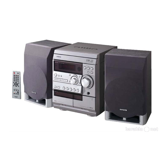
CD STEREO SYSTEM
SYSTEM
NSX–R11
• This Service Manual is the "Revision Publishing" and replaces "Simple Manual"
(S/M Code No. 09-023-455-6T1).
• If requiring information about the CD mechanism, see Service Manual of
www
BZG-2, (S/M Code No. 09-023-353-2N8).
.
http://www.xiaoyu163.com
CD
CASSEIVER
CX–NR11
x
ao
u163
y
i
S/M Code No. 09-024-455-6R1
http://www.xiaoyu163.com
NSX-R11
2 9
8
Q Q
3
6 7
1 3
1 5
BASIC CD MECHANISM : BZG-2 ZD9GNC1
BASIC TAPE MECHANISM : CMAT6Z2(1+1)ALPS
SPEAKER
SX–NR10
co
.
EZ(S)
9 4
2 8
0 5
8
2 9
9 4
2 8
REMOTE
CONTROLLER
RC–CAS03(VS)
m
9 9
9 9
Advertisement
Table of Contents

Related Manuals for Aiwa NSX-R11


Summary of Contents for Aiwa NSX-R11
- Page 1 NSX-R11 EZ(S) 3 7 63 1515 0 SERVICE MANUAL L 13942296513 BASIC CD MECHANISM : BZG-2 ZD9GNC1 CD STEREO SYSTEM BASIC TAPE MECHANISM : CMAT6Z2(1+1)ALPS REMOTE SYSTEM SPEAKER CASSEIVER CONTROLLER NSX–R11 CX–NR11 SX–NR10 RC–CAS03(VS) • This Service Manual is the "Revision Publishing" and replaces "Simple Manual"...
-
Page 2: Table Of Contents
http://www.xiaoyu163.com TABLE OF CONTENTS 3 7 63 1515 0 SPECIFICATIONS ................................3 PROTECTION OF EYES FROM LASER BEAM DURING SERVICING ............... 4 NOTE ON BEFORE STARTING REPAIR ........................5, 6 ELECTRICAL PARTS LIST (CX – NR11) ......................... 7 ~ 19 CHIP RESISTOR PART CODE ............................ -
Page 3: Specifications
http://www.xiaoyu163.com SPECIFICATIONS 3 7 63 1515 0 MAIN UNIT CX-NR11 CD PLAYER Laser Semiconductor laser (λ = 780 nm) TUNER D/A converter 1 bit dual FM tuning range 87.5 MHz to 108 MHz Signal - to - noise ratio 85 dB (1 kHz, 0 dB) FM usable sensitivity (IHF) 16.8 dBf Harmonic distortion... -
Page 4: Protection Of Eyes From Laser Beam During Servicing
http://www.xiaoyu163.com PROTECTION OF EYES FROM LASER BEAM DURING SERVICING 3 7 63 1515 0 CAUTION This set employs laser. Therefore, be sure to follow carefully the instructions below when servicing. Use of controls or adjustments or performance of proce- dures other than those specified herin may result in WARNING!! hazardous radiation exposure. -
Page 5: Note On Before Starting Repair
http://www.xiaoyu163.com NOTE ON BEFORE STARTING REPAIR 1. Forced discharge of electrolytic capacitor of power supply block 3 7 63 1515 0 When repair is going to be attempted in the set that uses relay circuit in the power supply block, electric potential is kept charged across the electrolytic capacitors (C101, 102) even though AC power cord is removed. - Page 6 http://www.xiaoyu163.com 3 7 63 1515 0 In such a case, check also if the POWER AMPLIFIER circuit or power supply circuit has any abnormalities or not. 2-2. Regarding reset There are cases that the machine does not work correctly because the MICROCOMPUTER is not reset even though the AC power cord is re-inserted, or the software reset (pressing the STOP key + POWER key) is performed.
-
Page 7: Electrical Parts List (Cx - Nr11)
http://www.xiaoyu163.com ELECTRICAL PARTS LIST (CX – NR11) = ! SAFTY PARTS = Components marked All components used on this model at the production line are shown in this service manual. 3 7 63 1515 0 However, please note that not all components will be available as spare parts for after-sales service. Components marked S and O are designated as spare parts for service and will be stocked at the spare parts centers. - Page 8 http://www.xiaoyu163.com = ! SAFTY PARTS = Components marked All components used on this model at the production line are shown in this service manual. 3 7 63 1515 0 However, please note that not all components will be available as spare parts for after-sales service. Components marked S and O are designated as spare parts for service and will be stocked at the spare parts centers.
- Page 9 http://www.xiaoyu163.com = ! SAFTY PARTS = Components marked All components used on this model at the production line are shown in this service manual. 3 7 63 1515 0 However, please note that not all components will be available as spare parts for after-sales service. Components marked S and O are designated as spare parts for service and will be stocked at the spare parts centers.
- Page 10 http://www.xiaoyu163.com = ! SAFTY PARTS = Components marked All components used on this model at the production line are shown in this service manual. 3 7 63 1515 0 However, please note that not all components will be available as spare parts for after-sales service. Components marked S and O are designated as spare parts for service and will be stocked at the spare parts centers.
- Page 11 http://www.xiaoyu163.com = ! SAFTY PARTS = Components marked All components used on this model at the production line are shown in this service manual. 3 7 63 1515 0 However, please note that not all components will be available as spare parts for after-sales service. Components marked S and O are designated as spare parts for service and will be stocked at the spare parts centers.
- Page 12 http://www.xiaoyu163.com = ! SAFTY PARTS = Components marked All components used on this model at the production line are shown in this service manual. 3 7 63 1515 0 However, please note that not all components will be available as spare parts for after-sales service. Components marked S and O are designated as spare parts for service and will be stocked at the spare parts centers.
- Page 13 http://www.xiaoyu163.com = ! SAFTY PARTS = Components marked All components used on this model at the production line are shown in this service manual. 3 7 63 1515 0 However, please note that not all components will be available as spare parts for after-sales service. Components marked S and O are designated as spare parts for service and will be stocked at the spare parts centers.
- Page 14 http://www.xiaoyu163.com = ! SAFTY PARTS = Components marked All components used on this model at the production line are shown in this service manual. 3 7 63 1515 0 However, please note that not all components will be available as spare parts for after-sales service. Components marked S and O are designated as spare parts for service and will be stocked at the spare parts centers.
- Page 15 http://www.xiaoyu163.com = ! SAFTY PARTS = Components marked All components used on this model at the production line are shown in this service manual. 3 7 63 1515 0 However, please note that not all components will be available as spare parts for after-sales service. Components marked S and O are designated as spare parts for service and will be stocked at the spare parts centers.
- Page 16 http://www.xiaoyu163.com = ! SAFTY PARTS = Components marked All components used on this model at the production line are shown in this service manual. 3 7 63 1515 0 However, please note that not all components will be available as spare parts for after-sales service. Components marked S and O are designated as spare parts for service and will be stocked at the spare parts centers.
- Page 17 http://www.xiaoyu163.com = ! SAFTY PARTS = Components marked All components used on this model at the production line are shown in this service manual. 3 7 63 1515 0 However, please note that not all components will be available as spare parts for after-sales service. Components marked S and O are designated as spare parts for service and will be stocked at the spare parts centers.
- Page 18 http://www.xiaoyu163.com = ! SAFTY PARTS = Components marked All components used on this model at the production line are shown in this service manual. 3 7 63 1515 0 However, please note that not all components will be available as spare parts for after-sales service. Components marked S and O are designated as spare parts for service and will be stocked at the spare parts centers.
- Page 19 http://www.xiaoyu163.com = ! SAFTY PARTS = Components marked All components used on this model at the production line are shown in this service manual. 3 7 63 1515 0 However, please note that not all components will be available as spare parts for after-sales service. Components marked S and O are designated as spare parts for service and will be stocked at the spare parts centers.
-
Page 20: Chip Resistor Part Code
http://www.xiaoyu163.com 3 7 63 1515 0 CHIP RESISTOR PART CODE Chip Resistor Part Coding Figure Resistor Code Value of resistor Chip resistor Dimensions (mm) Symbol Wattage Type Tolerance Resistor Code Form 1/16W 1005 0.35 1/16W 1608 0.45 1/10W 2125 1.25 0.45 1/8W 3216... -
Page 21: Transistor Illustration
http://www.xiaoyu163.com 3 7 63 1515 0 TRANSISTOR ILLUSTRATION B C E B C E E C B E C B 2SB1548 2SB1342 2SA1980G 2SC5343GL 2SD1933 2SA1981Y 2SC3331(T/U) S D G E C B L 13942296513 2SJ460 2SK360E 2SK2158 2SA1585SR 2SK2541 2SA1235F 2SD1306E 2SC2620B... -
Page 22: Schematic Diagram - 1 (Main 1 / 2)
http://www.xiaoyu163.com SCHEMATIC DIAGRAM – 1 (MAIN 1 / 2) 3 7 6 3 1 5 1 5 0 1 3 9 4 2 2 9 6 5 1 3 w w w u 1 6 3 – 23 – http://www.xiaoyu163.com... -
Page 23: Schematic Diagram - 2 (Main 2 / 2)
http://www.xiaoyu163.com SCHEMATIC DIAGRAM – 2 (MAIN 2 / 2) 3 7 6 3 1 5 1 5 0 1 3 9 4 2 2 9 6 5 1 3 w w w u 1 6 3 – 24 – http://www.xiaoyu163.com... -
Page 24: Schematic Diagram - 3 (Hp)
http://www.xiaoyu163.com SCHEMATIC DIAGRAM – 3 (HP) 3 7 63 1515 0 L 13942296513 u163 – 25 – http://www.xiaoyu163.com... -
Page 25: Schematic Diagram - 4 (Front / Deck)
http://www.xiaoyu163.com SCHEMATIC DIAGRAM – 4 (FRONT / DECK) 3 7 6 3 1 5 1 5 0 1 3 9 4 2 2 9 6 5 1 3 w w w u 1 6 3 – 27 – http://www.xiaoyu163.com... -
Page 26: Wiring - 3 (Pt)
http://www.xiaoyu163.com WIRING – 3 (PT) 3 7 63 1515 0 L 13942296513 u163 – 28 – http://www.xiaoyu163.com... -
Page 27: Schematic Diagram - 5 (Pt)
http://www.xiaoyu163.com SCHEMATIC DIAGRAM – 5 (PT) 3 7 63 1515 0 L 13942296513 u163 – 29 – http://www.xiaoyu163.com... -
Page 28: Wiring - 4 (Deck)
http://www.xiaoyu163.com WIRING – 4 (DECK) 3 7 6 3 1 5 1 5 0 DECK 1 DECK 2 1 3 9 4 2 2 9 6 5 1 3 P HEAD E / RP HEAD CNA301 CNA302 TO MAIN C.B TO MAIN C.B CN301 CN302... -
Page 29: Ic Block Diagram
http://www.xiaoyu163.com IC BLOCK DIAGRAM 3 7 6 3 1 5 1 5 0 1 3 9 4 2 2 9 6 5 1 3 w w w u 1 6 3 – 31 – http://www.xiaoyu163.com... -
Page 30: Fl (Hua - 13Ss09T) Grid Assignment / Pin Connection / Anode Connection
http://www.xiaoyu163.com FL (HUA – 13SS09T) GRID ASSIGNMENT / PIN CONNECTION / ANODE CONNECTION GRID ASSIGNMENT ANODE CONNECTION 3 7 6 3 1 5 1 5 0 1 3 9 4 2 2 9 6 5 1 3 PIN CONNECTION w w w u 1 6 3 –... -
Page 31: Ic Description
http://www.xiaoyu163.com IC DESCRIPTION PD780228GF-089-3BA µ 3 7 63 1515 0 Pin Name Pin No. Description O-MOTOR DECK motor output. O-SOL1 DECK1 solenoid output. O-SOL2 DECK2 solenoid output. O-STBY LED Standby LED output. (Not used) O-MUTE System mute ON/OFF output. O-KSCAN Key scan timing output. - Page 32 http://www.xiaoyu163.com 3 7 63 1515 0 Pin Name Description Pin No. I-SPEANA_1 A/D input for spectrum analyser level display. I-SPEANA_2 A/D input for spectrum analyser level display. I-SPEANA_3 A/D input for spectrum analyser level display. I-KEY 1 Key A/D input 1. I-KEY 2 Key A/D input 2.
-
Page 33: Adjustment (Tuner / Deck / Front)
http://www.xiaoyu163.com ADJUSTMENT (TUNER / DECK / FORNT) 3 7 63 1515 0 MAIN C.B PARTS SIDE T C942 L941 L802 L942 L953 L952 L901 SFR451 L907 L902 L905 L904 SFR452 MAIN C.B PATTERN SIDE L 13942296513 IC801 GN D DECK C.B MOTOR u163 –... - Page 34 http://www.xiaoyu163.com <TUNER Adjustment> 3 7 63 1515 0 1. VT Adjustment and Check (LW) Requirements Measuring instrument: Digital multimeter DIGITAL MULTIMETER Test point: VT, GND Adjustment point: L942 (1) Connect a digital multimeter to VT and GND. (2) Set the unit function to LW, and adjust the receiving frequency at 144 kHz. (3) Adjust L942 so that the digital multimeter indicates 1.3 ±...
- Page 35 http://www.xiaoyu163.com <MW/LW Adjustment> 3 7 63 1515 0 Make sure that the following settings are done before adjustment. Preparation Measuring instruments: Standard Signal Generator (S.S.G.) / Loop antenna / Oscilloscope / Millivoltmeter / Dummy resistor (6Ω) (1) Connect the measuring instruments as shown in the diagram below. (2) Keep a distance of 60cm between the loop antenna of signal generator and the one connected to the unit.
- Page 36 http://www.xiaoyu163.com 8. Auto-Stop Function Check (MW) 3 7 63 1515 0 Requirements: Same as Item 5. (1) Adjust the S.S.G setting to AM; carrier at 999 kHz; distortion rate at 30 %; source at 1 kHz, and output at 40 ~ 70 dBuV. (2) Start the tuning search mode, and check that the auto-stop function is applied at MW 999 kHz.
- Page 37 http://www.xiaoyu163.com <Deck Section> 3 7 63 1515 0 12. Tape Speed Adjustment (DECK 2) Requirements Measuring instruments: Wow-flutter meter (frequency counter) Test tape: TTA-100 (3 kHz) W OW &FLUTTER M ETE R Test point: HP OUT Adjustment point: DECK MOTOR SFR INPUT HP O UT (1) Connect the HP OUT terminal of the unit to the wow-flutter meter.
- Page 38 http://www.xiaoyu163.com 17. Playback Sensitivity Check (DECK 1, DECK 2) 3 7 63 1515 0 Requirements Measuring instrument: Millivoltmeter Test tape: TTA-200 (400 Hz) Test point: TP8 (Lch), TP9 (Rch) (1) Connect the CH1 of millivoltmeter to TP8 (Lch) and the CH2 to TP9 (Rch). (2) Insert the test tape (TTA-200) to DECK 1 to playback.
- Page 39 http://www.xiaoyu163.com <Front Section> 3 7 63 1515 0 FRONT C.B PATTERN SIDE KSCAN FRONT C.B PARTS SIDE L951 L 13942296513 20. Clock Adjustment FREQUE NCY CO UNTER Requirement Measuring instrument: Frequency counter Test point: CLOCK, GND CL OCK Adjustment point: L951 (1) While pressing and holding down the POWER button and the UP button, insert the AC plug.
-
Page 40: Cd Test Mode
http://www.xiaoyu163.com CD TEST MODE 3 7 63 1515 0 CD TEST MODE Ver. 3.0 1. Starting CD Test Mode While pressing and holding down the CD OPEN/CLOSE button, insert the AC plug to outlet. When test mode starts, the message, “ TEST” appears on the display. 2. -
Page 41: Mechanical Exploded View
http://www.xiaoyu163.com MECHANICAL EXPLODED VIEW 3 7 6 3 1 5 1 5 0 1 3 9 4 2 2 9 6 5 1 3 w w w u 1 6 3 – 43 – http://www.xiaoyu163.com... -
Page 42: Mechanical Parts List
88-911-101-110 FF-CABLE,11P 1.25 100MM O MC1031 8A-NFA-208-010 GUIDE,FL 100-25 ANFA L 13942296513 X MC1032 8C-NF9-621-010 PWB,FRONT CNF-9 O MC1033 87-B00-002-010 BADGE,AIWA 30 ABS SIL O MC1034 8C-NFA-009-010 PANEL,TRAY X MC1035 M8-BZG-29J-070 BZG-2 ZD9GNC1 O MC1036 8A-NF8-206-010 HLDR,PWB M O MC1037... -
Page 43: Color Name Table
http://www.xiaoyu163.com 3 7 63 1515 0 COLOR NAME TABLE Basic color symbol Color Basic color symbol Color Basic color symbol Color Black Cream Orange Green Gray Blue Transparent Blue Gold Pink Silver Titan Silver Brown Violet White Transparent White Yellow Transparent Yellow Metallic Blue Light Blue... -
Page 44: Tape Mechanism Exploded View
http://www.xiaoyu163.com TAPE MECHANISM EXPLODED VIEW 3 7 6 3 1 5 1 5 0 1 3 9 4 2 2 9 6 5 1 3 w w w u 1 6 3 – 46 – http://www.xiaoyu163.com... -
Page 45: Tape Mechanism Parts List
http://www.xiaoyu163.com TAPE MECHANISM PARTS LIST = ! SAFTY PARTS = Components marked All components used on this model at the production line are shown in this service manual. 3 7 63 1515 0 However, please note that not all components will be available as spare parts for after-sales service. Components marked S and O are designated as spare parts for service and will be stocked at the spare parts centers.