Sony Walkman WM-FX488 Service Manual
Radio cassette player
Hide thumbs
Also See for Walkman WM-FX488:
- Service manual (22 pages) ,
- Manual (3 pages) ,
- Operating instructions (2 pages)
Table of Contents
Advertisement
QQ
3 7 63 1515 0
SERVICE MANUAL
Ver 1.1 2003.01
TE
L 13942296513
www
.
Sony Corporation
9-874-239-02
Personal Audio Company
2003A0200-1
Published by Sony Engineering Corporation
© 2003.01
http://www.xiaoyu163.com
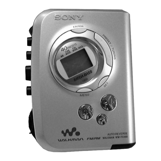
• Frequency range
FM: 87.5 - 108 MHz
• Power requirement s
1.5V DC, battery AA (R6) x 1
• Dimensions (w / h/ d)
Appr ox. 83.6 x 112.0 x 28.3 mm (3
excl. projecting parts and controls
• M ass
Appr ox. 138 g (4.9 oz) (main unit only)
• Supplied accessories
Stereo headphones or Stereo earphones (1)
Carrying case with belt clip(1)
Design and specifications are subject to change without notice.
Bat t ery lif e* (approximat e hours)
Tape playback
Radio reception
* Measured value by the standar d of JEITA (Japan Electr onics
and Information Technology Industries Association). (Using
a Sony HF series cassette tape)
**When using a Sony LR6(SG) "ST AMINA" alkaline dry
battery (produced in Japan).
Not e
• The battery life may be shorter depending on the operating
condition, the surrounding temperature and battery type.
x
ao
u163
y
i
http://www.xiaoyu163.com
WM-FX488
2 9
8
Model Name Using Similar Mechanism
MD Mechanism Type
SPECIFICATIONS
Q Q
3
6 7
1 3
1 5
AM: 531 - 1602 kHz (9kHz step)
AM: 530 - 1710 kHz (10kHz step)
× 4
× 1
3
⁄
1
⁄
1
⁄
inches)
8
2
8
Sony alkaline LR6 (SG)** Sony R6P (SR)
35
9
40
14
RADIO CASSETTE PLAYER
co
.
9 4
2 8
E Model
Chinese Model
NEW
MF-WMFX488-114
0 5
8
2 9
9 4
2 8
m
9 9
9 9
Advertisement
Table of Contents

Related Manuals for Sony Walkman WM-FX488


Summary of Contents for Sony Walkman WM-FX488
- Page 1 * Measured value by the standar d of JEITA (Japan Electr onics and Information Technology Industries Association). (Using a Sony HF series cassette tape) **When using a Sony LR6(SG) “ST AMINA” alkaline dry battery (produced in Japan). Not e • The battery life may be shorter depending on the operating condition, the surrounding temperature and battery type.
-
Page 2: Table Of Contents
WM-FX488 3 7 63 1515 0 TABLE OF CONTENTS Flexible Circuit Board Repairing Specifications ................1 • Keep the temperature of the soldering iron around 270°C during 1. GENERAL repairing............... 2 • Do not touch the soldering iron on the same conductor of the circuit board (within 3 times). -
Page 3: Disassembly
WM-FX488 SECTION 2 DISASSEMBLY 3 7 63 1515 0 The equipment can be removed using the following procedure. Cabinet (center) Main board Mechanism deck Belt, Capstan/reel motor (M601) Magnetic head (playback) (HP601) Cabinet (front) Holder, Cassette Note : Follow the disassembly procedure in the numerical order given. -
Page 4: Mechanism Deck
WM-FX488 3 7 63 1515 0 2-3. MECHANISM DECK Mechanism deck 1 Claws Cabinet (center) L 13942296513 2-4. BELT,CAPSTAN/REEL MOTOR (M601), MAGNETIC HEAD (PLAYBACK) (HP601) 2 Two screws (M1.4) 4 Two screws (M1.4) 3 Capstan/reel motor Mechanism deck (M601) •... -
Page 5: Holder, Cassette
WM-FX488 3 7 63 1515 0 2-5. “HOLDER, CASSETTE’’ 2 Move the hinge away from projection Projection Hinge 3 Move the hinge away from projection Hinge Projection 4 Spring (torsion) Hinge Hinge Holder, Cassete L 13942296513 CAUTIONS DURING ASSEMBLY Insert the spring (torsion) to the slot as shown in the figure. -
Page 6: Adjustments
WM-FX488 SECTION 3 ADJUSTMENTS 3 7 63 1515 0 3-1. MECHANICAL ADJUSTMENTS 3-2. ELECTRICAL ADJUSTMENTS PRECAUTION PRECAUTION 1. Clean the following parts with a denatured-alcohol-moistened • Supplied voltage : 1.3V. swab : • Switch and control position (MENU display) - Page 7 WM-FX488 Ver 1.1 2003.01 3 7 63 1515 0 • Repeat the procedures in each adjustment several times, and the TUNER SECTION 0 dB = 1µV frequency coverage and tracking adjustments should be finally AM Section done by the trimmer capacitors.
- Page 8 WM-FX488 3 7 63 1515 0 Adjustment Location : [MAIN BOARD] (SIDE A) CT1 : AM Tracking Adjustment TP30 : FM Sgnal input L2 : FM Tracking Adjustment L5 : AM Frequency Coverage Adjustment L4 : AM Tracking Adjustment...
-
Page 9: Diagrams
WM-FX488 SECTION 4 Ver 1.1 2003.01 DIAGRAMS 3 7 6 3 1 5 1 5 0 4-1. EXPLANATION OF IC TERMINALS Note on Schematic Diagram Waveforms • All capacitors are in µF unless otherwise noted. pF: µµF 50 WV or IC701 TC9329FA-CFX1740 (SYSTEM CONTROL) less are not indicated except for electrolytics and tantalums. -
Page 10: Block Diagram
WM-FX488 Ver 1.1 2003.01 4-2. BLOCK DIAGRAMS 3 7 6 3 1 5 1 5 0 E, CH FM/AM FRONT END (FM DISC) IF DET, FM MPX QUAD IC701 (1/2) LOUT (FM IF) RF IN IF IN SYSTEM LCD701... -
Page 11: Printed Wiring Boards
WM-FX488 Ver 1.1 2003.01 4-3. PRINTED WIRING BOARDS 3 7 6 3 1 5 1 5 0 Refer to page 9 for Notes. MAIN BOARD (SIDE B) MAIN BOARD (SIDE A) 1 3 9 4 2 2 9 6 5 1 3... -
Page 12: Schematic Diagram - Main Section (1/3)
WM-FX488 Ver 1.1 2003.01 4-4. SCHEMATIC DIAGRAM – MAIN SECTION (1/3) – 3 7 6 3 1 5 1 5 0 Refer to page 9 for Notes. 1 3 9 4 2 2 9 6 5 1 3 w w w u 1 6 3 http://www.xiaoyu163.com... -
Page 13: Schematic Diagram - Main Section (2/3)
WM-FX488 Ver 1.1 2003.01 4-5. SCHEMATIC DIAGRAM – MAIN SECTION (2/3) – Refer to page 9 for Notes. 3 7 6 3 1 5 1 5 0 1 3 9 4 2 2 9 6 5 1 3 w w w u 1 6 3 http://www.xiaoyu163.com... -
Page 14: Schematic Diagram - Main Section (3/3)
WM-FX488 Ver 1.1 2003.01 3 7 6 3 1 5 1 5 0 4-6. SCHEMATIC DIAGRAM – MAIN SECTION (3/3) – Refer to page 9 for Notes. 1 3 9 4 2 2 9 6 5 1 3 w w w u 1 6 3 http://www.xiaoyu163.com... -
Page 15: Ic Block Diagrams
WM-FX488 3 7 63 1515 0 4-7. IC BLOCK DIAGRAMS IC1 TA2154FN (EL) BUFF FM/AM/TV PW SW 1/8 OR BUFF 1/16 IF BUFF LEVEL BUFF TV RF FM IF AM IF FM/TV FM MPX FM RF IC301 TA2160FN (EL) L 13942296513 RF &... - Page 16 WM-FX488 3 7 63 1515 0 IC601 MM1279XVBE MOTIVE CONTROL DRIVER CIRCUIT MOTIVE SOFT MOTIVE LOGIC SWITCH /OSC INVERTER BIAS VREF SPEED CURRENT REFERENCE CONTROL CONTROL VOLTAGE START OUTPUT BIAS L 13942296513 u163 http://www.xiaoyu163.com...
-
Page 17: Exploded Views
WM-FX488 SECTION 5 Ver 1.1 2003.01 EXPLODED VIEWS 3 7 63 1515 0 NOTE : • The mechanical parts with no reference number in the • -XX, -X mean standardized parts, so they exploded views are not supplied. may have some difference from the original •... -
Page 18: Mechanism Deck Section
WM-FX488 3 7 63 1515 0 5-2. MECHANISM DECK SECTION (MF-WMFX488-114) supplied supplied not supplied supplied L 13942296513 supplied supplied supplied M601 HP601 Ref. No. Part No. Description Remark Ref. No. Part No. Description Remark 3-920-990-21 SPRING (UD), COMPRESSION... -
Page 19: Electrical Parts List
WM-FX488 Ver 1.1 2003.01 SECTION 6 MAIN ELECTRICAL PARTS LIST 3 7 63 1515 0 NOTE : • Due to standardization, replacements in the • Items marked “ * ”are not stocked since they When indicating parts by reference num- parts list may be different from the parts are seldom required for routine service. - Page 20 WM-FX488 Ver 1.1 2003.01 MAIN 3 7 63 1515 0 Ref. No. Part No. Description Remark Ref. No. Part No. Description Remark C704 1-162-919-11 CERAMIC CHIP 22PF < COIL > C705 1-135-259-11 TANTAL. CHIP 10uF 6.3V C706 1-125-837-91 CERAMIC CHIP 6.3V...
- Page 21 WM-FX488 Ver 1.1 2003.01 MAIN 3 7 63 1515 0 Ref. No. Part No. Description Remark Ref. No. Part No. Description Remark R113 1-216-829-11 METAL CHIP 4.7K 1/10W R714 1-216-833-11 METAL CHIP 1/10W R715 1-216-821-11 METAL CHIP 1/10W R114...
- Page 22 WM-FX488 3 7 63 1515 0 REVISION HISTORY Clicking the version allows you to jump to the revised page. Also, clicking the version at the upper right on the revised page allows you to jump to the next revised page.