Sun Microsystems Enterprise 250 Owner's Manual
Hide thumbs
Also See for Enterprise 250:
- Owner's manual (324 pages) ,
- Rack mounting manual (178 pages) ,
- Conversion manual (92 pages)

Related Manuals for Sun Microsystems Enterprise 250


Summary of Contents for Sun Microsystems Enterprise 250
- Page 1 Sun Enterprise 250 Server Owner’s Guide A Sun Microsystems, Inc. Business 901 San Antonio Road Palo Alto, , CA 94303-4900 Part No: 805-3389-11 Revision A, June 1998...
- Page 2 USA 650 960-1300 fax 650 969-9131...
- Page 3 Sun Enterprise 250 Server Owner’s Guide Part No: 805-3389-11 Revision A, June 1998...
- Page 4 52.227-14(g)(2)(6/87) and FAR 52.227-19(6/87), or DFAR 252.227-7015(b)(6/95) and DFAR 227.7202-3(a). Sun, Sun Microsystems, the Sun logo, and Solaris are trademarks or registered trademarks of Sun Microsystems, Inc. in the United States and in other countries. All SPARC trademarks are used under license and are trademarks or registered trademarks of SPARC International, Inc.
-
Page 5: Table Of Contents
Contents Regulatory Compliance Statements xxii Preface xxviii System Overview 1 About the Sun Enterprise 250 Server 1 Locating Front Panel Features 3 Locating Rear Panel Features 5 About the Status and Control Panel 6 Photographic Tour of System 11 System View 11... - Page 6 What Next 51 How to Configure a Local Graphics Console 51 Before You Begin 51 What to Do 52 What Next 53 Preparing to Install or Replace Parts 55 Sun Enterprise 250 Server Owner’s Guide ♦ Revision A, June 1998...
- Page 7 How to Power Off the System 55 What to Do 55 How to Power On the System 56 Before You Begin 56 What to Do 57 How to Initiate a Reconfiguration Boot 58 Before You Begin 58 What to Do 59 What Next 60 How to Remove the Side Access Panel 60 Before You Begin 60...
- Page 8 About Flash PROM Jumpers 93 About the SCSI Removable Media Bays and the External SCSI Port 95 Target Devices 95 Bus Length 96 External SCSI Cabling and Termination 97 Multi-initiator Support 98 Sun Enterprise 250 Server Owner’s Guide ♦ Revision A, June 1998...
- Page 9 Configuration Rules 98 Removing and Installing Main Logic Board Components 99 How to Remove the Main Logic Board 100 Before You Begin 100 Video Demonstration 100 What to Do 100 What Next 102 How to Install the Main Logic Board 102 Before You Begin 102 Video Demonstration 102 What to Do 102...
- Page 10 How to Install the NVRAM/TOD Module 124 What to Do 125 What Next 125 Removing and Installing Storage Devices 127 How to Remove the Removable Media Assembly (RMA) 128 Sun Enterprise 250 Server Owner’s Guide ♦ Revision A, June 1998...
- Page 11 Before You Begin 128 Video Demonstration 128 What to Do 128 What Next 131 How to Install the Removable Media Assembly (RMA) 132 Video Demonstration 132 What to Do 132 What Next 135 How to Remove a Disk Drive 135 Before You Begin 135 What to Do 135 What Next 137...
- Page 12 Before You Begin 155 What to Do 155 What Next 156 How to Remove the LED/Keyswitch Assembly 157 Before You Begin 157 Video Demonstration 157 What to Do 157 Sun Enterprise 250 Server Owner’s Guide ♦ Revision A, June 1998...
- Page 13 What Next 159 How to Install the LED/Keyswitch Assembly 160 Video Demonstration 160 What to Do 160 What Next 162 How to Remove the Disk Cage Assembly 163 Before You Begin 163 What to Do 163 What Next 166 How to Install the Disk Cage Assembly 167 What to Do 167 What Next 170 How to Remove the Floor Casters Assembly 170...
- Page 14 What Next 197 How to Add an Ethernet Interface 198 Before You Begin 198 What to Do 198 What Next 200 How to Attach a Twisted-Pair Ethernet (TPE) Cable 200 Sun Enterprise 250 Server Owner’s Guide ♦ Revision A, June 1998 xiii...
- Page 15 Before You Begin 200 What to Do 201 What Next 201 How to Attach an MII Ethernet Transceiver 202 Before You Begin 202 What to Do 202 What Next 204 How to Boot the System Using the Standard Ethernet Interface 204 Before You Begin 204 What to Do 205 What Next 205...
- Page 16 How to Eject a Compact Disc With Software Commands 222 Before You Begin 222 What to Do 222 What Next 222 How to Eject a Compact Disc Manually 223 Sun Enterprise 250 Server Owner’s Guide ♦ Revision A, June 1998...
- Page 17 What to Do 223 What Next 223 How to Eject a Compact Disc in an Emergency 224 Before You Begin 224 What to Do 224 What Next 225 About the Tape Drive and Tape Cartridges 225 Handling and Storing Tape Cartridges 226 Thermal Conditioning 226 How to Insert a Tape Cartridge 226 What to Do 226...
- Page 18 What to Do 254 Results 255 About Solstice SyMON Software 255 About Remote System Control (RSC) 256 For More Information About Troubleshooting Your System 257 Error Indications 257 Sun Enterprise 250 Server Owner’s Guide ♦ Revision A, June 1998 xvii...
- Page 19 Software Commands 261 About Diagnosing Specific Problems 267 Network Communications Failure 267 Power-on Failures 269 Video Output Failure 270 Disk or CD-ROM Drive Failure 270 SCSI Controller Failures 271 Power Supply Failure 272 DIMM Failure 272 Environmental Failures 273 Connector Pinouts 277 Reference for the Serial Port A and B Connectors 277 Reference for the Parallel Connector 279 Reference for the SCSI Connector 280...
- Page 20 Einhaltung der Richtlinien für Laser 303 Conformité aux normes de sécurité 303 Mesures de sécurité 304 Symboles 304 Modification du matériel 305 Positionnement d’un produit Sun 305 Conformité SELV 305 Ergonomie européenne 305 Sun Enterprise 250 Server Owner’s Guide ♦ Revision A, June 1998...
- Page 21 Normativas de seguridad 307 Precauciones de seguridad 307 Símbolos 307 Modificaciones en el equipo 308 Ubicación de un producto Sun 308 Cumplimiento de la normativa SELV 308 Normativa ergonómica europea 309 Conexión del cable de alimentación eléctrica 309 Batería de litio 310 Tapa de la unidad del sistema 310 Aviso de cumplimiento con requisitos de láser 310...
- Page 22 Improving File Loading Time 331 Avoiding Using Proxy Servers to Access the AnswerBook2 Server 331 Quitting the Video Player 333 Adjusting the Brightness of ShowMe TV Files 334 Index to Videos 335 Sun Enterprise 250 Server Owner’s Guide ♦ Revision A, June 1998...
-
Page 23: Regulatory Compliance Statements
4 Federal Communications Commission (FCC) — USA 4 Department of Communications (DOC) — Canada 4 Voluntary Control Council for Interference (VCCI) — Japan Please read the appropriate section that corresponds to the marking on your Sun product before attempting to install the product. Caution - For important safety precautions to follow when installing or servicing this system, please see Appendix C. - Page 24 Networking connections can be made using unshielded twisted-pair (UTP) cables. Modifications: Any modifications made to this device that are not approved by Sun Microsystems, Inc. may void the authority granted to the user by the FCC to operate this equipment.
- Page 25 DOC Class A Notice - Avis DOC, Classe This Class A digital apparatus meets all requirements of the Canadian Interference-Causing Equipment Regulations. Cet appareil numérique de la classe A respecte toutes les exigences du Règlement sur le matériel brouilleur du Canada. DOC Class B Notice - Avis DOC, Classe This Class B digital apparatus meets all requirements of the Canadian Interference-Causing Equipment Regulations.
-
Page 26: Declaration Of Conformity
1. This equipment may not cause harmful interference. 2. This equipment must accept any interference that may cause undesired operation. European Union This equipment complies with the following requirements of the EMC Directive 89/ 336/EEC: Sun Enterprise 250 Server Owner’s Guide ♦ Revision A, June 1998... - Page 27 This equipment complies with the following requirements of the Low Voltage Directive 73/23/EEC: TABLE P–2 EC Type Examination Certificates: EN60950/ TUV GS Certificate # S9871518 – Model Sun Enterprise 250, floor-mount IEC950 (1993) unit TUV Bauart Certificate # R9871519 – Model Sun Enterprise 250R, rack-mount unit EN60950 w/ CB Scheme Certificate # UL2214-113363/USA...
- Page 28 4 Omni Way UCHL04-203 Springfield, Linlithgow Chelmsford, MA 01824 USA West Lothian, EH49 7LR Tel: (508) 442-0599 Scotland, United Kingdom Fax: (508) 250-5059 Tel: 1506 670000 Fax: 1506 672323 Sun Enterprise 250 Server Owner’s Guide ♦ Revision A, June 1998 xxvii...
-
Page 29: Preface
Enterprise 250 server. Look at the titles of the modules and you’ll find the cue words that direct you to the categories of questions and answers, such as: 4 How to . - Page 30 C shell superuser machine_name# Bourne shell and Korn shell Bourne shell and Korn shell superuser Conventions The following table describes the typographic conventions used in this book. Sun Enterprise 250 Server Owner’s Guide ♦ Revision A, June 1998 xxix...
-
Page 31: Related Documentation
Right The side to your right as you face the front of the system. Related Documentation The following documents contain topics that relate to the information in the Sun Enterprise 250 Server Owner’s Guide. - Page 32 Improper handling by unqualified personnel can cause serious damage to this equipment. Unqualified personnel who tamper with this equipment may be held liable for any resultant damage to the equipment. Sun Enterprise 250 Server Owner’s Guide ♦ Revision A, June 1998 xxxi...
- Page 33 Some procedures in this document must be performed by trained maintenance providers. Only people who have been trained at the Sun Microsystems training facilities (or by Sun Microsystems affiliates) and have been certified as required by local and national laws are considered qualified. Ordering Sun Documents SunDocsSM is a distribution program for Sun Microsystems technical documentation.
-
Page 34: Sun Welcomes Your Comments
World Wide Web: http://www.sun.com/sunexpress/ Sun Documentation on the Web The docs.sun.com web site enables you to access Sun technical documentation on the Web. You can browse the docs.sun.com archive or search for a specific book title or subject at: http://docs.sun.com. -
Page 35: System Overview
CHAPTER System Overview This chapter introduces you to the Sun Enterprise 250 server and explains some of its features. Information covered in this chapter includes: 4 “About the Sun Enterprise 250 Server” on page 1 4 “Locating Front Panel Features” on page 3 4 “Locating Rear Panel Features”... - Page 36 SCSI port provided on the system’s rear panel. Additional external tape devices can be supported with appropriate PCI host adapter cards. The Enterprise 250 server can easily be connected to either a 10-Mbps or a 100-Mbps Ethernet by means of an auto-sensing Ethernet interface provided on the system’s main logic board.
-
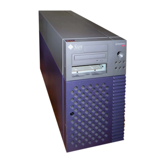
Page 37: Locating Front Panel Features
For more information about the power supplies, see “About Power Supplies” on page 87. The Enterprise 250 server can easily be installed in a standard 19-inch rack. An optional rackmounting kit is available for installing the server into any 29- to 34-inch deep EIA 19-inch rack with at least 6 rack units (10.5 inches) of vertical... - Page 38 To lock the door, simply turn the key 90 degrees counterclockwise and remove the key. This same key also controls the front panel keyswitch. Sun Enterprise 250 Server Owner’s Guide ♦ Revision A, June 1998...
-
Page 39: Locating Rear Panel Features
Figure 1–2 Locating Rear Panel Features The illustration below shows the system features that are accessible from the rear panel. System Overview... -
Page 40: About The Status And Control Panel
A grounding screw is located in the upper-left corner of the rear panel. When connecting a deskside Enterprise 250 server to any rack-mounted peripheral, be sure to connect an appropriate grounding strap between the server’s grounding screw and the rack enclosure. - Page 41 Figure 1–4 The front panel keyswitch controls the power-on mode of the system. The following table describes the function of each switch setting. TABLE 1–1 Name Icon Description Power-On Turns the system power on. Diagnostics Turns the system power on and runs power-on self-test (POST) and OpenBoot diagnostics (OBDiag).
- Page 42 (POST) diagnostics and blinks rapidly during OpenBoot diagnostic (OBDiag) tests. It lights steadily when any fault is detected (including a fault also reported by any other LED). Sun Enterprise 250 Server Owner’s Guide ♦ Revision A, June 1998...
- Page 43 TABLE 1–2 (continued) Name Icon Description Activity This green LED blinks continuously to indicate that the system is operating normally. Disk fault This yellow LED lights steadily to indicate a fault in one of the hard disk drives. When this LED is lit, one or more disk LEDs may also be lit, indicating the source of the fault.
- Page 44 Sun Enterprise 250 Server Owner’s Guide ♦ Revision A, June 1998...
-
Page 45: Photographic Tour Of System
CHAPTER Photographic Tour of System System View... - Page 46 Figure 2–1 1. “Side Access Panel” on page 19 Sun Enterprise 250 Server Owner’s Guide ♦ Revision A, June 1998...
-
Page 47: Internal System Components
2. “Internal System Components” on page 13 3. “Disk Drives” on page 20 4. “Removable Media Components” on page 15 5. “LED/Keyswitch Assembly” on page 41 For additional information, see: 4 Appendix D 4 Appendix B Internal System Components Photographic Tour of System... - Page 48 Sun Enterprise 250 Server Owner’s Guide ♦ Revision A, June 1998 Figure 2–2...
-
Page 49: Removable Media Components
6. “Power Supply” on page 33 7. “Main Logic Board Components” on page 17 8. “Power Distribution Board” on page 35 9. “Fan Tray Assembly” on page 40 10. “Disk Cage Assembly” on page 37 11. “UltraSCSI Backplane” on page 39 Removable Media Components Photographic Tour of System... - Page 50 Figure 2–3 12. “Diskette Drive” on page 22 Sun Enterprise 250 Server Owner’s Guide ♦ Revision A, June 1998...
-
Page 51: Main Logic Board Components
13. “CD-ROM Drive” on page 23 14. “Tape Drive” on page 25 15. “Removable Media Assembly” on page 21 Main Logic Board Components Photographic Tour of System... - Page 52 Sun Enterprise 250 Server Owner’s Guide ♦ Revision A, June 1998 Figure 2–4...
-
Page 53: Side Access Panel
16. “NVRAM/TOD Module” on page 32 17. “SSP Paddle Card and Cable” on page 31 18. “PCI Cards” on page 30 19. “Main Logic Board” on page 26 20. “CPU Modules” on page 28 21. “Memory Modules” on page 29 Side Access Panel Photographic Tour of System... -
Page 54: Disk Drives
For information related to this part, see: 4 “How to Remove the Side Access Panel” on page 60 4 “How to Install the Side Access Panel” on page 62 Disk Drives Sun Enterprise 250 Server Owner’s Guide ♦ Revision A, June 1998... -
Page 55: Removable Media Assembly
Figure 2–6 For information related to this part, see: 4 “About Internal Disk Drives” on page 83 4 “How to Remove a Disk Drive” on page 135 4 “How to Install a Disk Drive” on page 137 Removable Media Assembly Photographic Tour of System... -
Page 56: Diskette Drive
4 “About the SCSI Removable Media Bays and the External SCSI Port” on page 95 4 “How to Remove the Removable Media Assembly (RMA)” on page 128 4 “How to Install the Removable Media Assembly (RMA)” on page 132 Diskette Drive Sun Enterprise 250 Server Owner’s Guide ♦ Revision A, June 1998... -
Page 57: Cd-Rom Drive
Figure 2–8 For information related to this part, see: 4 Chapter 11 4 “How to Remove the Diskette Drive” on page 144 4 “How to Install the Diskette Drive” on page 146 CD-ROM Drive Photographic Tour of System... - Page 58 4 Chapter 11 4 “How to Remove a CD-ROM Drive or Tape Drive” on page 139 4 “How to Install a CD-ROM Drive or Tape Drive” on page 141 Sun Enterprise 250 Server Owner’s Guide ♦ Revision A, June 1998...
-
Page 59: Tape Drive
Tape Drive Figure 2–10 For information related to this part, see: 4 “About the SCSI Removable Media Bays and the External SCSI Port” on page 95 4 Chapter 11 4 “How to Remove a CD-ROM Drive or Tape Drive” on page 139 Photographic Tour of System... -
Page 60: Main Logic Board
4 “How to Install a CD-ROM Drive or Tape Drive” on page 141 Main Logic Board Sun Enterprise 250 Server Owner’s Guide ♦ Revision A, June 1998... - Page 61 Figure 2–11 For information related to this part, see: 4 “How to Remove the Main Logic Board” on page 100 4 “How to Install the Main Logic Board” on page 102 4 “About the Standard Ethernet Port” on page 89 4 “About the Serial Ports”...
-
Page 62: Cpu Modules
4 “About the Main Logic Board Jumpers” on page 90 4 “About Serial Port Jumpers” on page 92 4 “About Flash PROM Jumpers” on page 93 4 Appendix A CPU Modules Sun Enterprise 250 Server Owner’s Guide ♦ Revision A, June 1998... -
Page 63: Memory Modules
Figure 2–12 For information related to this part, see: 4 “About CPU Modules” on page 78 4 “How to Remove a CPU Module” on page 109 4 “How to Install a CPU Module” on page 110 Memory Modules Photographic Tour of System... -
Page 64: Pci Cards
For information related to this part, see: 4 “About Memory” on page 76 4 “How to Remove a Memory Module” on page 105 4 “How to Install a Memory Module” on page 107 PCI Cards Sun Enterprise 250 Server Owner’s Guide ♦ Revision A, June 1998... -
Page 65: Ssp Paddle Card And Cable
Figure 2–14 For information related to this part, see: 4 “About Peripheral Component Interconnect (PCI) Buses” on page 80 4 “How to Remove a PCI Card” on page 112 4 “How to Install a PCI Card” on page 114 SSP Paddle Card and Cable Photographic Tour of System... -
Page 66: Nvram/Tod Module
4 “How to Remove the SSP Paddle Card” on page 117 4 “How to Install the SSP Paddle Card” on page 120 4 “About Remote System Control (RSC)” on page 256 NVRAM/TOD Module Sun Enterprise 250 Server Owner’s Guide ♦ Revision A, June 1998... -
Page 67: Power Supply
Figure 2–16 For information related to this part, see: 4 “How to Remove the NVRAM/TOD Module” on page 123 4 “How to Install the NVRAM/TOD Module” on page 124 Power Supply Photographic Tour of System... - Page 68 For information related to this part, see: 4 “About Power Supplies” on page 87 4 “How to Remove a Power Supply” on page 153 4 “How to Install a Power Supply” on page 155 Sun Enterprise 250 Server Owner’s Guide ♦ Revision A, June 1998...
-
Page 69: Power Distribution Board
Power Distribution Board Photographic Tour of System... - Page 70 Figure 2–18 For information related to this part, see: Sun Enterprise 250 Server Owner’s Guide ♦ Revision A, June 1998...
-
Page 71: Disk Cage Assembly
4 “How to Remove the Power Distribution Board” on page 184 4 “How to Install the Power Distribution Board” on page 185 Disk Cage Assembly Photographic Tour of System... - Page 72 For information related to this part, see: 4 “How to Remove the Disk Cage Assembly” on page 163 4 “How to Install the Disk Cage Assembly” on page 167 Sun Enterprise 250 Server Owner’s Guide ♦ Revision A, June 1998...
-
Page 73: Ultrascsi Backplane
UltraSCSI Backplane Figure 2–20 For information related to this part, see: Photographic Tour of System... -
Page 74: Fan Tray Assembly
4 “How to Remove the UltraSCSI Backplane” on page 179 4 “How to Install the UltraSCSI Backplane” on page 182 Fan Tray Assembly Figure 2–21 For information related to this part, see: Sun Enterprise 250 Server Owner’s Guide ♦ Revision A, June 1998... -
Page 75: Led/Keyswitch Assembly
4 “How to Remove the Fan Tray Assembly” on page 150 4 “How to Install the Fan Tray Assembly” on page 151 LED/Keyswitch Assembly Figure 2–22 For information related to this part, see: Photographic Tour of System... - Page 76 4 “How to Remove the LED/Keyswitch Assembly” on page 157 4 “How to Install the LED/Keyswitch Assembly” on page 160 Sun Enterprise 250 Server Owner’s Guide ♦ Revision A, June 1998...
-
Page 77: System Setup
CHAPTER System Setup This chapter explains how to attach all cords and cables needed to get the Sun Enterprise 250 server up and running. Where software is involved, this chapter explains some of what you need to do, and points you to the appropriate software manuals for the rest. -
Page 78: How To Install The Enterprise 250 Server
How to Install the Enterprise 250 Server Before You Begin The Sun Enterprise 250 server is a general-purpose server, which you can use for many types of applications. Exactly how you set up your machine depends in some measure upon what you want it to do. - Page 79 2. Ensure that the system’s front panel keyswitch is in the Standby position. See “About the Status and Control Panel” on page 6. 3. Connect the AC power cord to the power inlet at the rear of the power supply. Connect the other end to a grounded AC power outlet.
- Page 80 4 If you’re using a PCI network interface, see the documentation accompanying the PCI network card. 8. Install the security lock block to prevent unauthorized removal of the side access panel, if required. Sun Enterprise 250 Server Owner’s Guide ♦ Revision A, June 1998...
- Page 81 12. Load the Sun Enterprise 250 Server Hardware AnswerBook online documentation. See the installation instructions that accompany this CD-ROM disc in the Sun Enterprise 250 documentation set. 13. Decide on your internal disk array configuration. For information about possible configurations, see “About Disk Array Configurations and Concepts”...
-
Page 82: How To Install The Security Lock Block
To secure the power supplies as well, loop a cable through the lock block and through each power supply handle. Secure the cable with a padlock or combination lock. Sun Enterprise 250 Server Owner’s Guide ♦ Revision A, June 1998... -
Page 83: About Setting Up A Console
For instructions, see “How to Attach an Alphanumeric Terminal” on page 50. 2. Establish a tip connection from another Sun system. For information about establishing a tip connection, see the OpenBoot 3.x Command Reference Manual, an online version of which is included with the Solaris System Administrator AnswerBook that ships with Solaris software. -
Page 84: How To Attach An Alphanumeric Terminal
Reference Manual, an online version of which is included with the Solaris System Administrator AnswerBook that ships with Solaris software. What to Do 1. Connect the terminal’s data cable to serial port A on the server’s rear panel. Sun Enterprise 250 Server Owner’s Guide ♦ Revision A, June 1998... -
Page 85: What Next
Figure 3–4 2. Connect the terminal’s power cable to an AC outlet. 3. Set the terminal to receive: 4 At 9600 baud 4 An 8-bit signal with no parity and 1 stop bit See the documentation accompanying your terminal for more information. What Next You can now issue system commands and view system messages. -
Page 86: What To Do
Tighten the thumbscrews to secure the connection. Figure 3–5 3. Connect the monitor’s power cord to an appropriate AC power outlet. 4. Attach the keyboard cable to the server’s keyboard/mouse port. Sun Enterprise 250 Server Owner’s Guide ♦ Revision A, June 1998... -
Page 87: What Next
Figure 3–6 5. Attach the mouse cable to the appropriate receptacle on the keyboard. What Next You can now issue system commands and view system messages. Continue with your installation or diagnostic procedure as needed. System Setup... - Page 88 Sun Enterprise 250 Server Owner’s Guide ♦ Revision A, June 1998...
-
Page 89: Preparing To Install Or Replace Parts
CHAPTER Preparing to Install or Replace Parts This chapter tells you what you need to know, and need to do, before opening the system to install, remove, or replace parts. Tasks covered in this chapter include: 4 “How to Power Off the System” on page 55 4 “How to Power On the System”... -
Page 90: How To Power On The System
If a terminal or local console is not already connected to the system, you need to install one before continuing the startup procedure. 4 See “About Setting Up a Console” on page 49. Sun Enterprise 250 Server Owner’s Guide ♦ Revision A, June 1998... -
Page 91: What To Do
Note - Do not use this power-on procedure if you have just installed an internal or external storage device, or any new part that plugs into the main logic board. To power on the system after adding any of these options, see “How to Initiate a Reconfiguration Boot”... -
Page 92: How To Initiate A Reconfiguration Boot
Caution - Before you power on the system, make sure that the side access panel and all plastic outer panels and doors are properly installed. Sun Enterprise 250 Server Owner’s Guide ♦ Revision A, June 1998... -
Page 93: What To Do
For additional information, see Chapter 12. 4. When the system banner is displayed on the monitor or terminal, immediately enter the Stop-a sequence on the Sun keyboard or press the Break key on the terminal keyboard. The system banner contains the Ethernet address and host ID. To enter the Stop-a sequence, hold down the Stop key and press the a key. -
Page 94: What Next
Before You Begin Complete this task: 4 “How to Power Off the System” on page 55 Video Demonstration Figure 4–3 Sun Enterprise 250 Server Owner’s Guide ♦ Revision A, June 1998... -
Page 95: What To Do
Click on the icon above for a video demonstration. Click here for Appendix E. What to Do 1. Remove the security lock block (if present). See “How to Install the Security Lock Block” on page 48. 2. Loosen the two captive screws securing the side panel to the rear of the chassis. Figure 4–4 3. -
Page 96: What Next
Before You Begin Remember to detach the antistatic wrist or foot strap from the system chassis sheet metal. Video Demonstration Figure 4–6 Click on the icon above for a video demonstration. Sun Enterprise 250 Server Owner’s Guide ♦ Revision A, June 1998... -
Page 97: What To Do
Click here for Appendix E. What to Do 1. Locate the hooks beneath the top surface of the side panel and insert them into the slots in the top of the system chassis. Figure 4–7 2. Slide the panel toward the front of the system until it contacts the system’s plastic front panel. -
Page 98: What Next
Before You Begin Complete this task: 4 “How to Power Off the System” on page 55 You must have the following items: 4 Antistatic wrist or foot strap Sun Enterprise 250 Server Owner’s Guide ♦ Revision A, June 1998... -
Page 99: What To Do
The following items can be used as an antistatic surface: 4 The bag used to wrap a Sun replacement part 4 The shipping container used to package a Sun replacement part 4 Sun electrostatic discharge (ESD) mat, PN 250-1088 (available through your Sun sales representatives) 4 Disposable ESD mat, shipped with replacement parts or options 3. -
Page 100: Reference For Installation And Service: Tools Required
The following tools are required to install and service the system: 4 Screwdriver, Phillips #1 4 Screwdriver, Phillips #2 4 Screwdriver, long flat-blade #2 4 ESD mat, Sun PN 250-1088, or equivalent Sun Enterprise 250 Server Owner’s Guide ♦ Revision A, June 1998... - Page 101 4 Grounding wrist or foot strap The latter two items help protect the server against damage due to electrostatic discharge. For more information, see “How to Avoid Electrostatic Discharge” on page 64. Preparing to Install or Replace Parts...
- Page 102 Sun Enterprise 250 Server Owner’s Guide ♦ Revision A, June 1998...
-
Page 103: Hardware Configuration
CHAPTER Hardware Configuration This chapter describes the hardware configuration of the system. Topics covered in this chapter include: 4 “About Reliability, Availability, and Serviceability Features” on page 69 4 “About Memory” on page 76 4 “About CPU Modules” on page 78 4 “About Peripheral Component Interconnect (PCI) Buses”... -
Page 104: Error Correction And Parity Checking
Status LEDs eliminate guesswork and simplify problem diagnosis for enhanced serviceability. Sun Enterprise 250 Server Owner’s Guide ♦ Revision A, June 1998... -
Page 105: Hot-Pluggable Disk Drives
Status and control panel LEDs are described in “About the Status and Control Panel” on page 6. Disk drive and power supply LEDs are described in “Error Indications” on page 257. Hot-Pluggable Disk Drives The “hot-plug” feature of the system’s internal disk drives permits the removal and installation of drives while the system is operational. - Page 106 For more information about error messages generated by the environmental monitoring subsystem, see “Environmental Failures” on page 273. For additional Sun Enterprise 250 Server Owner’s Guide ♦ Revision A, June 1998...
-
Page 107: N+1 Power Supply Redundancy
details about the status and control panel LEDs, see “About the Status and Control Panel” on page 6. N+1 Power Supply Redundancy The system can accommodate one or two power supplies. All system configurations can operate with only one power supply installed. A second supply can be used to provide N+1 redundancy, allowing the system to continue operating should one of the power supplies fail. -
Page 108: Hardware Watchdog Mechanism
Solaris release you are running. Hardware Watchdog Mechanism To detect and respond to system hang conditions, the Enterprise 250 server features a hardware watchdog mechanism—a hardware timer that is continually reset as long as the operating system is running. In the event of a system hang, the operating system is no longer able to reset the timer. -
Page 109: Remote System Control (Rsc)
The RSC software works with the System Service Processor (SSP) on the Enterprise 250 main logic board. The RSC and SSP support both serial and Ethernet connections to a remote console. -
Page 110: About Memory
Memory slots are organized into four banks, with each bank comprising four slots. The system reads from, or writes to, all four DIMMs in a bank at the same time. Sun Enterprise 250 Server Owner’s Guide ♦ Revision A, June 1998... -
Page 111: Configuration Rules
DIMMs, therefore, must be added four at a time in the same bank. The following figure shows the memory banks on the main logic board. Figure 5–2 Configuration Rules Memory DIMMs must be added four at a time within the same bank, and each bank used must have four identical capacity DIMMs installed (for example, four 32-Mbyte DIMMs, or four 64-Mbyte DIMMs). -
Page 112: About Cpu Modules
(VIS). VIS provides high levels of multimedia performance, including real-time video compression/decompression and two streams of MPEG-2 decompression at full broadcast quality with no additional hardware support. Sun Enterprise 250 Server Owner’s Guide ♦ Revision A, June 1998... -
Page 113: Configuration Rules
The system’s main logic board provides slots for two UltraSPARC II CPU modules. Each processor module includes one CPU chip with integrated cache memory for data and instructions, as well as 1 Mbyte or more of external SRAM cache memory. Processor modules communicate with the system’s main memory and I/O subsystem via the system’s high-speed Ultra Port Architecture (UPA) data bus. -
Page 114: About Peripheral Component Interconnect (Pci) Buses
Older PCI cards communicate over 32-bit PCI buses, while many newer cards communicate over wider 64-bit buses. All four PCI slots will accept either 32-bit or 64-bit wide cards. Sun Enterprise 250 Server Owner’s Guide ♦ Revision A, June 1998... - Page 115 Older PCI cards operate at 5 VDC, while newer cards are designed to operate on 3.3 VDC. Cards that require 5 volts will not operate in 3.3-volt slots, and 3.3-volt cards will not operate in 5-volt slots. “Universal” PCI cards are designed to operate on either 3.3 volts or 5 volts, so these cards can be inserted into either type of slot.
-
Page 116: Configuration Rules
Examples of high-throughput interfaces are dual-channel UltraSCSI host adapters and ATM-622 interfaces. Overall system availability may also be improved by installing redundant storage or network interfaces on separate PCI buses. Sun Enterprise 250 Server Owner’s Guide ♦ Revision A, June 1998... -
Page 117: About Internal Disk Drives
About Internal Disk Drives Figure 5–6 The Enterprise 250 server supports up to six internal, hot-pluggable UltraSCSI disk drives. Drives are 3.5-inches wide and either 1-inch or 1.6-inches high. All internal drives are supported by the 40-Mbyte per second UltraSCSI interface on the system’s main logic board. - Page 118 The exact hot-plug procedure depends on which version of the Solaris operating environment you are using. For the complete procedure, please refer to Platform Notes: Sun Enterprise 250 Server, available on the Sun Enterprise 250 Server Owner’s Guide ♦ Revision A, June 1998...
-
Page 119: Configuration Rules
/devices/pci@1f,4000/scsi@3/sd@c,0 Configuration Rules Disk drives must be Sun standard 3.5-inch wide UltraSCSI-compatible drives, either 1 inch or 1.6 inches high. UltraSCSI-compatible 1-inch and 1.6-inch high drives can be mixed in the same system. The SCSI IDs for the disks are hardwired on the disk backplanes. There is no need to set any SCSI ID jumpers on the disk drives themselves. - Page 120 (RMA). The removable media SCSI cable provides the termination for the internal SCSI bus. For information about implementing RAID configurations, see “About Disk Array Configurations and Concepts” on page 209. Sun Enterprise 250 Server Owner’s Guide ♦ Revision A, June 1998...
-
Page 121: About Power Supplies
About Power Supplies Figure 5–8 A central power distribution board delivers DC power for all internal system components. The system’s power supplies plug in to connectors on this board, and Hardware Configuration... - Page 122 For information about removing and installing power supplies, see “How to Remove a Power Supply” on page 153 and “How to Install a Power Supply” on page 155. Sun Enterprise 250 Server Owner’s Guide ♦ Revision A, June 1998...
-
Page 123: About The Standard Ethernet Port
For additional details, see “Power Supply LEDs” on page 259. Note - Enterprise 250 power supplies will shut down automatically in response to certain over-temperature and power fault conditions (see “Environmental Monitoring and Control” on page 71). To recover from an automatic shutdown, you must disconnect the AC power cord, wait roughly 10 seconds, and then reconnect the power cord. -
Page 124: About The Serial Ports
4 J2604 and J2605 are used to configure the serial ports for either EIA-423 or EIA-232D operation. For information about the EIA-423/232D jumper settings, see “About Serial Port Jumpers” on page 92. Sun Enterprise 250 Server Owner’s Guide ♦ Revision A, June 1998... - Page 125 4 J2702, J2704, and J2804 are used to affect the operation of the flash PROM located on the main logic board. For information about the flash PROM jumper settings, see “About Flash PROM Jumpers” on page 93. The illustration below shows the jumper locations on the main logic board. Figure 5–10 Jumpers are marked on the main logic board with identification numbers.
-
Page 126: About Serial Port Jumpers
EIA-423 levels are the default standard for North American users. EIA-232D levels are required for digital telecommunication in nations of the European Community. The figure below shows the jumper locations, and the table describes their function. Figure 5–11 Sun Enterprise 250 Server Owner’s Guide ♦ Revision A, June 1998... -
Page 127: About Flash Prom Jumpers
TABLE 5–3 Default Shunt on Shunt on Shunt Jumper Pins 1 + 2 Selects Pins 2 + 3 Selects on Pins J2604 EIA-232D EIA-423 2 + 3 J2605 EIA-232D EIA-423 2 + 3 About Flash PROM Jumpers The system uses flash PROMs to permit the reprogramming of specific code blocks that are held in non-volatile system memory, and to permit remote reprogramming of that code by an authorized system administrator over a local area network. - Page 128 Power-on position or to the Diagnostics position, the flash PROM is write-enabled. For descriptions of the various keyswitch settings, see “About the Status and Control Panel” on page 6. Sun Enterprise 250 Server Owner’s Guide ♦ Revision A, June 1998...
-
Page 129: About The Scsi Removable Media Bays And The External Scsi Port
For descriptions of the various keyswitch settings, see “About the Status and Control Panel” on page 6. For more information about flash PROM programming, see the documentation supplied with the flash PROM update CD-ROM. About the SCSI Removable Media Bays and the External SCSI Port The removable media assembly located at the top front of the system provides mounting bays for two 5.25-inch, half-height (1.6-inch) SCSI devices. -
Page 130: Bus Length
4 For 1 to 3 devices, the maximum bus length is 3 meters (9.84 feet) 4 For 4 to 7 devices, the maximum bus length is 1.5 meters (4.92 feet) You must include the Enterprise 250 internal bus length (0.5 meter/1.7 feet) in your bus length calculations. -
Page 131: External Scsi Cabling And Termination
See the documentation supplied with the device. 4 If all external mass storage devices use 68-pin connectors, connect all non-Sun devices to the system first and connect a Sun autoterminating device to the end of the chain. 4 If external mass storage devices consist of 68-pin devices and 50-pin devices, connect the Sun 68-pin devices to the system first and terminate the chain with a... -
Page 132: Multi-Initiator Support
4 For 1 to 3 devices, the maximum bus length is 3 meters (9.84 feet) 4 For 4 to 7 devices, the maximum bus length is 1.5 meters (4.92 feet) You must include the Enterprise 250 internal bus length (0.5 meter/1.7 feet) in your bus length calculations. - Page 133 CHAPTER Removing and Installing Main Logic Board Components This chapter describes how to remove and install the main logic board components within the system. For a list of part numbers for field-replaceable units and optional equipment, see “Illustrated Parts Breakdown” on page 313. Tasks covered in this chapter include: 4 “How to Remove the Main Logic Board”...
-
Page 134: How To Remove The Main Logic Board
1. Disconnect any external cables attached to the rear panel of the system. Be sure to note where each cable attaches to the rear panel. See “Locating Rear Panel Features” on page 5. Sun Enterprise 250 Server Owner’s Guide ♦ Revision A, June 1998... - Page 135 2. Disconnect the internal cables from the main logic board. Press the tab on the cable connector to detach each cable. a. Disconnect the two power cables at connectors J2902 and J2903. b. Disconnect the two power sense cables at connectors J2901 and J4501. c.
-
Page 136: How To Install The Main Logic Board
Click on the icon above for a video demonstration. Click here for Appendix E. What to Do 1. Remove the main logic board from its antistatic packaging and place it on an antistatic mat. Sun Enterprise 250 Server Owner’s Guide ♦ Revision A, June 1998... - Page 137 Retain the packaging and use it to pack and return the defective board. 2. Set the jumpers on the replacement main logic board so that they are the same as the settings on the old board. See “About the Main Logic Board Jumpers” on page 90 for more information about jumper locations and settings.
- Page 138 What Next Remove the NVRAM module from the replacement board and install it on the old board for return to Sun Microsystems. See “How to Install the NVRAM/TOD Module” on page 124. Complete these tasks to transfer the components that you removed from the old main logic board to the new board: 4 “How to Install the SSP Paddle Card”...
-
Page 139: How To Remove A Memory Module
How to Remove a Memory Module Before You Begin Complete these tasks: 4 “How to Power Off the System” on page 55 4 “How to Remove the Side Access Panel” on page 60 4 “How to Avoid Electrostatic Discharge” on page 64 Caution - Dual inline memory modules (DIMMs) are made of electronic components that are extremely sensitive to static electricity. - Page 140 3. Grasp the top corners of the memory module and pull it out of its socket. Place the module on an antistatic mat. What Next To replace a memory module, complete this task: 4 “How to Install a Memory Module” on page 107 Sun Enterprise 250 Server Owner’s Guide ♦ Revision A, June 1998...
-
Page 141: How To Install A Memory Module
How to Install a Memory Module Before You Begin Caution - Dual inline memory modules (DIMMs) are made of electronic components that are extremely sensitive to static electricity. Static from your clothes or work environment can destroy the modules. Do not remove any DIMM from its antistatic packaging until you are ready to install it on the main logic board. - Page 142 You must also perform a reconfiguration boot so that your system is able to recognize the new device(s). For additional information, see: 4 “How to Initiate a Reconfiguration Boot” on page 58 Sun Enterprise 250 Server Owner’s Guide ♦ Revision A, June 1998...
-
Page 143: How To Remove A Cpu Module
How to Remove a CPU Module Before You Begin Complete these tasks: 4 “How to Power Off the System” on page 55 4 “How to Remove the Side Access Panel” on page 60 4 “How to Avoid Electrostatic Discharge” on page 64 Caution - CPU modules are delicate. -
Page 144: How To Install A Cpu Module
4 “How to Install a CPU Module” on page 110 How to Install a CPU Module Before You Begin Know the configuration guidelines for installing CPU modules, see: 4 “About CPU Modules” on page 78 Complete these tasks: Sun Enterprise 250 Server Owner’s Guide ♦ Revision A, June 1998... - Page 145 4 “How to Power Off the System” on page 55 4 “How to Remove the Side Access Panel” on page 60 4 “How to Avoid Electrostatic Discharge” on page 64 What to Do 1. In the CPU card cage, locate the slot for the CPU module that you are installing on the main logic board.
-
Page 146: How To Remove A Pci Card
1. Disconnect any external cable(s) from the external faceplate of the PCI card. 2. Disconnect all cables connected to the PCI card internal connectors. 3. Remove the Phillips screw that secures the faceplate to the system rear panel. Sun Enterprise 250 Server Owner’s Guide ♦ Revision A, June 1998... - Page 147 Use a magnetized screwdriver, if possible, to prevent the screw from falling into the system chassis. Figure 6–10 4. Pull the PCI card out of its slot. Hold the card by the faceplate and its opposite edge, and pull each end in turn until the card is freed from its slot.
-
Page 148: How To Install A Pci Card
2. Insert the PCI card into the appropriate slot on the main logic board. To install a PCI short card: a. Insert the faceplate end of the card into the appropriate slot opening in the rear panel. Sun Enterprise 250 Server Owner’s Guide ♦ Revision A, June 1998... - Page 149 b. Push the card into the corresponding connector on the main logic board. Figure 6–12 To install a PCI long card: i. Insert the faceplate end of the card into the appropriate slot opening in the rear panel, while at the same time aligning the opposite end of the card with the long card slot guide.
- Page 150 You must also perform a reconfiguration boot so that your system is able to recognize the new device(s). For additional information, see: 4 “How to Initiate a Reconfiguration Boot” on page 58 Sun Enterprise 250 Server Owner’s Guide ♦ Revision A, June 1998...
- Page 151 How to Remove the SSP Paddle Card The System Service Processor (SSP) paddle card is mounted in the top slot opening in the system’s rear panel. Before you Begin Complete these tasks: 4 “How to Power Off the System” on page 55 4 “How to Remove the Side Access Panel”...
- Page 152 4. Disconnect the SSP data cable from the main logic board at connector J4201. a. Lift up the collar on the SSP cable connector. b. Remove the SSP data cable from the connector. Sun Enterprise 250 Server Owner’s Guide ♦ Revision A, June 1998...
- Page 153 Figure 6–16 5. Place the SSP card and data cable on an antistatic mat. 6. If you are not replacing the SSP card, install a PCI filler panel into the vacated SSP slot. Secure the filler panel with the screw from the PCI faceplate. What Next To replace an SSP card, complete this task: 4 “How to Install the SSP Paddle Card”...
- Page 154 Insert the cable into the connector so that the cable’s exposed contacts are facing away from the system rear panel. c. Press down on each side of the collar to secure the cable in the connector. Sun Enterprise 250 Server Owner’s Guide ♦ Revision A, June 1998...
- Page 155 Figure 6–18 2. Insert the SSP card into the SSP rear panel opening. The SSP paddle card mounts in the top slot opening in the system’s rear panel. Removing and Installing Main Logic Board Components...
- Page 156 When you are ready to restart the system, be sure to run POST and OpenBoot Diagnostic tests to verify that the system functions correctly with the new parts you have just installed. For additional information, see Chapter 12. Sun Enterprise 250 Server Owner’s Guide ♦ Revision A, June 1998...
- Page 157 How to Remove the NVRAM/TOD Module Caution - This procedure must be performed by a qualified service-trained maintenance provider. Persons who remove any of the outer panels to access this equipment must observe all safety precautions and comply with skill level requirements, certification, and all applicable local and national laws.
- Page 158 Caution - Use only NVRAM/TOD modules that have been specifically programmed for a Sun Enterprise 250 server. Sun Enterprise 250 Server Owner’s Guide ♦ Revision A, June 1998...
- Page 159 Note - If you are installing a new NVRAM/TOD module, the NVRAM/TOD must be programmed by a Sun authorized service representative before your system can resume normal operation. When you are ready to restart the system, be sure to run POST and OpenBoot Diagnostic tests to verify that the system functions correctly with the new parts you have just installed.
- Page 160 Sun Enterprise 250 Server Owner’s Guide ♦ Revision A, June 1998...
-
Page 161: Storage Devices
CHAPTER Removing and Installing Storage Devices This chapter describes how to remove and install storage devices and removable media devices. For a list of part numbers for field-replaceable units and optional equipment, see “Illustrated Parts Breakdown” on page 313. Tasks covered in this chapter include: 4 “How to Remove the Removable Media Assembly (RMA)”... - Page 162 Click on the icon above for a video demonstration. Click here for Appendix E. What to Do 1. Disconnect the diskette data cable (if present) from the top of the UltraSCSI backplane at connector J0502. Sun Enterprise 250 Server Owner’s Guide ♦ Revision A, June 1998...
- Page 163 Figure 7–2 2. Disconnect the removable media power cable from the UltraSCSI backplane at connector J0104. 3. Disconnect the removable media SCSI cable from the top of the UltraSCSI backplane at connector J0501. Leave all other cabling connected to the rear of the drives in the removable media assembly.
- Page 164 Be sure that you feed all the cables carefully out of the RMA chassis opening as you remove the assembly. Note - At this point all the power and data cables are attached to the rear of the drives installed in the assembly. Sun Enterprise 250 Server Owner’s Guide ♦ Revision A, June 1998...
- Page 165 Figure 7–4 7. Place the assembly on an antistatic mat. What Next For information about removing drives from, or installing drives in the removable media assembly, see: 4 “How to Remove the Diskette Drive” on page 144 4 “How to Install the Diskette Drive” on page 146 4 “How to Remove a CD-ROM Drive or Tape Drive”...
- Page 166 3. Slide the removable media assembly into the system chassis. Make sure that the cables are not caught between the removable media assembly and the chassis as you slide the assembly into the chassis. Sun Enterprise 250 Server Owner’s Guide ♦ Revision A, June 1998...
- Page 167 Figure 7–6 4. Tighten the two captive Phillips screws securing the removable media assembly to the system chassis. Figure 7–7 Removing and Installing Storage Devices...
- Page 168 8. If applicable, connect the diskette data cable to the SCSI backplane at connector J0502. 9. Connect the removable media power cable to the UltraSCSI backplane at connector J0104. Figure 7–8 Sun Enterprise 250 Server Owner’s Guide ♦ Revision A, June 1998...
-
Page 169: How To Remove A Disk Drive
What Next To reassemble the system, complete these tasks: 4 “How to Install the Fan Tray Assembly” on page 151 4 “How to Install the Side Access Panel” on page 62 How to Remove a Disk Drive The system’s disk “hot-plug” feature lets you remove a disk drive without shutting down the operating system or turning off the system power. - Page 170 Swing the handle out away from the drive until you feel the drive connector disengage from the backplane. Figure 7–9 7. Holding the drive by the handle, slide it out of the drive bay. Place the drive on an antistatic mat. Sun Enterprise 250 Server Owner’s Guide ♦ Revision A, June 1998...
-
Page 171: How To Install A Disk Drive
Note - When you reinstall the drive (or a replacement drive), be sure to install it in the same drive bay as the one from which it was just removed. What Next If you removed the drive as part of another procedure, complete the other procedure now. - Page 172 Note - If you are replacing a drive that you removed previously, be sure to install the drive in the same drive bay as the one you removed. Figure 7–10 Sun Enterprise 250 Server Owner’s Guide ♦ Revision A, June 1998...
- Page 173 7. Holding the drive by its handle, fit the drive into the guide rails at the top and bottom of the drive bay. 8. Slide the drive into the bay until it barely contacts the backplane. 9. Press carefully on the center of the drive and watch as the handle begins to close.
- Page 174 1. Disconnect the SCSI data and power cables from the rear of the CD-ROM or tape drive. Figure 7–12 2. Remove the four screws securing the drive in the removable media assembly. There are two screws on each side of the drive. Sun Enterprise 250 Server Owner’s Guide ♦ Revision A, June 1998...
- Page 175 Figure 7–13 3. Slide the drive out the front of its bay in the removable media assembly. Push the drive from the rear to start the removal process. 4. Place the drive on an antistatic mat. What Next To replace the CD-ROM or tape drive, complete this task: 4 “How to Install a CD-ROM Drive or Tape Drive”...
- Page 176 5. Insert and tighten the four flat-head Phillips screws that secure the drive in its bay. There are two screws on each side that secure the drive in the RMA. Sun Enterprise 250 Server Owner’s Guide ♦ Revision A, June 1998...
- Page 177 Figure 7–15 6. Connect the SCSI data and power cables to their corresponding connectors at the rear of the drive. The connectors are keyed so that they install in only one way. Figure 7–16 Note - Wide SCSI removable media devices require a 68-to-50 pin SCSI adapter. These devices only operate in narrow SCSI mode.
-
Page 178: How To Remove The Diskette Drive
Click on the icon above for a video demonstration. Click here for Appendix E. What to Do 1. Disconnect the diskette data cable and the removable media power cable from the rear of the diskette drive. Sun Enterprise 250 Server Owner’s Guide ♦ Revision A, June 1998... - Page 179 Figure 7–18 2. Remove the four Phillips screws securing the drive to the removable media assembly. There are two screws located on each side of the drive. Figure 7–19 3. Slide the drive out the front of its bay in the removable media assembly. Push the drive from the rear to start the removal process.
-
Page 180: How To Install The Diskette Drive
Click on the icon above for a video demonstration. Click here for Appendix E. What to Do 1. If necessary, remove the metal filler panel from the diskette drive bay in the removable media assembly. Sun Enterprise 250 Server Owner’s Guide ♦ Revision A, June 1998... - Page 181 Pinch the two metal retainers together to release the filler panel from the front of the RMA enclosure. 2. If necessary, remove the plastic filler panel from the RMA plastic cover. Squeeze the two retainer posts together to release the filler panel from the RMA plastic cover.
- Page 182 You must also perform a reconfiguration boot so that your system is able to recognize the new device(s). For additional information, see: 4 “How to Initiate a Reconfiguration Boot” on page 58 Sun Enterprise 250 Server Owner’s Guide ♦ Revision A, June 1998...
-
Page 183: Miscellaneous Assemblies
CHAPTER Removing and Installing Miscellaneous Assemblies This chapter describes how to remove and install miscellaneous assemblies within the system. For a list of part numbers for field-replaceable units and optional equipment, see “Illustrated Parts Breakdown” on page 313. Tasks covered in this chapter include: 4 “How to Remove the Fan Tray Assembly”... -
Page 184: How To Remove The Fan Tray Assembly
Press the tab to release the connector. Figure 8–1 2. Deflect the tab that secures the fan tray in the upper guide. 3. Slide the fan tray out of the system. Sun Enterprise 250 Server Owner’s Guide ♦ Revision A, June 1998... - Page 185 Hold the tray at the center so it pulls out evenly. Figure 8–2 What Next To replace the fan tray assembly, complete this task: 4 “How to Install the Fan Tray Assembly” on page 151 How to Install the Fan Tray Assembly What to Do 1.
- Page 186 Connect the end of the cable that is labeled P2. The connector is keyed and attaches in only one way. Press the connector until the tab locks the cable in place. Sun Enterprise 250 Server Owner’s Guide ♦ Revision A, June 1998...
-
Page 187: How To Remove A Power Supply
Figure 8–4 What Next To reassemble the system, complete this task: 4 “How to Install the Side Access Panel” on page 62 How to Remove a Power Supply Before You Begin It is not necessary to power off the system if you are removing a redundant power supply. - Page 188 5. If you are not replacing the power supply immediately, install a power supply filler panel. The filler panel is needed to maintain proper system cooling and prevent electromagnetic interference. a. Insert the filler panel into the bay. Sun Enterprise 250 Server Owner’s Guide ♦ Revision A, June 1998...
-
Page 189: How To Install A Power Supply
b. Fasten the two Phillips screws that secure the filler panel to the chassis. What Next To replace a power supply, complete this task: 4 “How to Install a Power Supply” on page 155 How to Install a Power Supply Before You Begin If you are installing a redundant power supply, it is not necessary to power off the system. - Page 190 The fan should start spinning and both LEDs should light within three seconds of completing a hot-plug installation (or after restoring power to the system). For more information, see: Sun Enterprise 250 Server Owner’s Guide ♦ Revision A, June 1998...
- Page 191 To activate the power supply, turn the front panel keyswitch from the Power-On position to the Diagnostics position, and then back to the Power-On position. Alternatively, you may press the Power-On key on a Sun Type-5 keyboard attached to the system. For descriptions of the various keyswitch settings, see “About the Status and Control Panel”...
- Page 192 3. Pull off the RMA plastic cover from the front of the removable media assembly. Grasp both sides of the cover and pull it away from the front of the system. Sun Enterprise 250 Server Owner’s Guide ♦ Revision A, June 1998...
- Page 193 4. Remove the Phillips screw that secures the LED/keyswitch assembly to the front of the chassis. Figure 8–9 5. Pull the top part of the assembly away from the chassis and lift the bottom tab free from the slot in the chassis wall. 6.
- Page 194 Align the clips on either side of the cover with the small rectangular slots in the chassis wall. Push evenly on both sides of the cover to secure it to the chassis. Sun Enterprise 250 Server Owner’s Guide ♦ Revision A, June 1998...
- Page 195 Figure 8–11 8. Grasp the corner of the LED ribbon cable, and fold the cable under itself, so that the label at the end is facing up. Make sure that the adhesive strip at the corner of the cable is also facing up. 9.
- Page 196 When you are ready to restart the system, be sure to run POST and OpenBoot Diagnostic tests to verify that the system functions correctly with the new parts you have just installed. For additional information, see Chapter 12. Sun Enterprise 250 Server Owner’s Guide ♦ Revision A, June 1998...
- Page 197 How to Remove the Disk Cage Assembly Before You Begin Complete these tasks: 4 “How to Power Off the System” on page 55 4 “How to Remove the Side Access Panel” on page 60 4 “How to Avoid Electrostatic Discharge” on page 64 4 “How to Remove the Fan Tray Assembly”...
- Page 198 Pull the bottom center edge of the panel outward until it disengages from the chassis. Lift the panel off the system and set it aside. Sun Enterprise 250 Server Owner’s Guide ♦ Revision A, June 1998...
- Page 199 Figure 8–14 4. Carefully lower the chassis onto its closed side. Enlist the help of another person to accomplish this safely. Do not lift the chassis using the plastic panels at the front or the side of the chassis. Roll the system onto a solid surface that spaces the unit about 2 inches (5 cm) off the floor;...
- Page 200 Place the assembly on an antistatic mat. What Next To replace the disk cage assembly, complete this task: 4 “How to Install the Disk Cage Assembly” on page 167 Sun Enterprise 250 Server Owner’s Guide ♦ Revision A, June 1998...
- Page 201 How to Install the Disk Cage Assembly What to Do 1. Lift the disk cage assembly into the side of the chassis. Orient the disk cage so that the open drive bays are facing the front of the chassis. Grasp the free end of the LED ribbon cable (from the LED/keyswitch assembly) and pull it out the front of the disk bay opening to make room for the disk cage.
- Page 202 11. Reconnect the remaining cables to the rear of the UltraSCSI backplane: a. Connect the UltraSCSI data cable to connector J0102. b. Connect the UltraSCSI power cable to connector J0101. Sun Enterprise 250 Server Owner’s Guide ♦ Revision A, June 1998...
- Page 203 c. Connect the keyswitch cable (from the LED/keyswitch assembly) to connector J0601. d. Connect the keyswitch/LED cable to connector J0103. Figure 8–17 12. Replace the plastic outer panel that partially covers the top of the chassis: a. Insert the hooks on the underside of the panel into the corresponding slots in the chassis.
- Page 204 When you reinstall the disk drives, it is important to return each drive to its original location. How to Remove the Floor Casters Assembly Before You Begin Complete this task: 4 “How to Power Off the System” on page 55 Sun Enterprise 250 Server Owner’s Guide ♦ Revision A, June 1998...
- Page 205 What to Do 1. Carefully turn the system chassis upside down. Enlist the help of another person to accomplish this safely. Do not lift the chassis using the plastic panels at the front or the side of the chassis. Place the system onto a solid surface that spaces the unit about 2 inches (5 cm) off the floor;...
- Page 206 To replace the floor casters assembly with foot glides, complete this task: 4 “How to Install the Chassis Foot Glides” on page 176 How to Install the Floor Casters Assembly Before You Begin Complete these tasks: Sun Enterprise 250 Server Owner’s Guide ♦ Revision A, June 1998...
- Page 207 4 “How to Power Off the System” on page 55 4 “How to Remove the Chassis Foot Glides” on page 174 What to Do 1. Carefully turn the system chassis upside down. Enlist the help of another person to accomplish this safely. Do not lift the chassis using the plastic panels at the front or the side of the chassis.
- Page 208 Enlist the help of another person to accomplish this safely. Do not lift the chassis using the plastic panels at the front or the side of the chassis. How to Remove the Chassis Foot Glides Before You Begin Complete this task: Sun Enterprise 250 Server Owner’s Guide ♦ Revision A, June 1998...
- Page 209 4 “How to Power Off the System” on page 55 What to Do 1. Carefully turn the system chassis upside down. Enlist the help of another person to accomplish this safely. Do not lift the chassis using the plastic panels at the front or the side of the chassis.
- Page 210 These brackets should already be installed on your system. If they are missing, install the two mounting brackets provided with the foot glides. Use two Phillips screws to attach each bracket. Sun Enterprise 250 Server Owner’s Guide ♦ Revision A, June 1998...
- Page 211 Figure 8–22 3. Carefully return the chassis to its upright position. Enlist the help of another person to accomplish this safely. Do not lift the chassis using the plastic panels at the front or the side of the chassis. Removing and Installing Miscellaneous Assemblies...
- Page 212 Sun Enterprise 250 Server Owner’s Guide ♦ Revision A, June 1998...
- Page 213 CHAPTER Removing and Installing Backplanes and Cables This chapter describes how to remove and install system backplanes and cables. For a list of part numbers for field-replaceable units and optional equipment, see “Illustrated Parts Breakdown” on page 313. Tasks covered in this chapter include: 4 “How to Remove the UltraSCSI Backplane”...
- Page 214 2. From the front of the disk cage, slide the center divider half way out of the cage. Figure 9–1 3. Free the backplane from the six posts that support it at the rear of the disk cage. Sun Enterprise 250 Server Owner’s Guide ♦ Revision A, June 1998...
- Page 215 Push down on the top edge of the backplane and pull it away from the posts. 4. Slide the backplane out of the opening at the base of the disk cage. Place the backplane on an antistatic mat. Figure 9–2 What Next To replace the UltraSCSI backplane, complete this task: 4 “How to Install the UltraSCSI Backplane”...
- Page 216 Lift the backplane slightly so that each post rests in the narrow part of a keyhole. Figure 9–3 3. Push the cage center divider back into the disk cage as far as it can go. Sun Enterprise 250 Server Owner’s Guide ♦ Revision A, June 1998...
- Page 217 The center divider should engage the two large holes in the center of the backplane. 4. Replace the two screws that secure the cage center divider and the backplane to the disk cage assembly. Figure 9–4 What Next To reassemble the system, complete these tasks: 4 “How to Install the Disk Cage Assembly”...
-
Page 218: Distribution Board
2. Loosen the two captive Phillips screws that secure the board to its mounting brackets. One screw is located at the top edge, and the other is located at the bottom edge of the power distribution board. Sun Enterprise 250 Server Owner’s Guide ♦ Revision A, June 1998... - Page 219 Figure 9–5 3. Remove the board from the chassis, and place it on an antistatic mat. What Next To replace the power distribution board, complete this task: 4 “How to Install the Power Distribution Board” on page 185 How to Install the Power Distribution Board What to Do 1.
- Page 220 Connect the two power sense cables at connectors J0201 and J0202. d. Connect the DC power cables at connectors J0204, J0205, and J0206. e. Connect the UltraSCSI power cable at connector J0207. Sun Enterprise 250 Server Owner’s Guide ♦ Revision A, June 1998...
-
Page 221: How To Connect The System Cables
Note - Part numbers listed in this section are correct as of the manual publication date but are subject to change without notice. Consult your authorized Sun sales representative or service provider to confirm a part number prior to ordering a replacement part. - Page 222 Routed behind fan tray assembly. From: Main Logic Board (J1801) Cable To: UltraSCSI Backplane (J0102) Keyswitch/ Routed behind fan tray assembly. From: Power Distribution Board LED Cable (J0401) To: UltraSCSI Backplane (J0103) Sun Enterprise 250 Server Owner’s Guide ♦ Revision A, June 1998...
- Page 223 TABLE 9–1 (continued) Cable Name Connections Routing and Management Removable Includes connectors for two RMA From: UltraSCSI Backplane (J0501) Media SCSI devices. SCSI Cable To: CD-ROM/Tape Drive SCSI Connector Removable Includes connectors for two RMA From: UltraSCSI Backplane (J0104) Media SCSI devices and one optional Power Cable To: CD-ROM/Tape/Diskette...
- Page 224 4 1 4-pin Power Sense/I C Cable — 530-2480 11 Diskette Data Cable — 530-2439 5 1 6-pin Power Sense/Control Cable — 12 Fan Tray Cable — 530-2685 530-2481 Sun Enterprise 250 Server Owner’s Guide ♦ Revision A, June 1998...
- Page 225 TABLE 9–2 (continued) Description Part Number 6 U ltraSCSI Power Cable — 530-2443 13 LED/Keyswitch Assembly — 540-3604 7 U ltraSCSI Data Cable — 530-2446 14 SSP Paddle Card and Cable — 501-4818 To install this part, see “How to Install the LED/Keyswitch Assembly” on page 160. To install this part, see “How to Install the SSP Paddle Card”...
- Page 226 Figure 9–8 Sun Enterprise 250 Server Owner’s Guide ♦ Revision A, June 1998...
- Page 227 Figure 9–9 What Next To reassemble the system, complete these tasks: 4 “How to Install the Fan Tray Assembly” on page 151 4 “How to Install the Side Access Panel” on page 62 Removing and Installing Backplanes and Cables...
- Page 228 Sun Enterprise 250 Server Owner’s Guide ♦ Revision A, June 1998...
-
Page 229: Administration And Networking
CHAPTER Administration and Networking This chapter focuses on administrative tasks associated with Ethernet interfaces and the disk array. Tasks covered in this chapter include: 4 “How to Configure the Standard Ethernet Interface” on page 196 4 “How to Add an Ethernet Interface” on page 198 4 “How to Attach a Twisted-Pair Ethernet (TPE) Cable”... - Page 230 Before You Begin You must perform the following tasks: 4 Complete the prerequisite steps in “How to Install the Enterprise 250 Server” on page 44. 4 Determine which of the two Ethernet ports you want to use; see “About Network Interface Options”...
- Page 231 IP address. 3. Resume the installation of the system. See “How to Install the Enterprise 250 Server” on page 44. When installing the operating system, you may be prompted to enter the host name and IP address of the machine.
-
Page 232: How To Add An Ethernet Interface
You must perform the following tasks: 4 Install the system; see “How to Install the Enterprise 250 Server” on page 44. 4 Install any additional PCI Ethernet interface cards that you wish to configure; see “How to Install a PCI Card” on page 114. - Page 233 the operating system software is installed. For more information, see the installation instructions accompanying the Solaris software. 2. Determine the IP address for the interface. An IP address must be assigned by your network administrator. Each interface on a network must have a unique IP address. 3.
- Page 234 If you are installing an additional Ethernet interface, you must perform the following tasks: 4 Install the system; see “How to Install the Enterprise 250 Server” on page 44. 4 Install a PCI Ethernet interface card; see “How to Install a PCI Card” on page 114.
- Page 235 MII port, see “How to Attach an MII Ethernet Transceiver” on page 202. What Next If you are installing your system, complete the installation procedure. Return to: 4 “How to Install the Enterprise 250 Server” on page 44 Administration and Networking...
-
Page 236: How To Attach An Mii Ethernet Transceiver
If you are adding an Ethernet interface, you must have already performed the following tasks: 4 Installed the system; see “How to Install the Enterprise 250 Server” on page 44 4 Installed a PCI Ethernet interface card; see “How to Install a PCI Card” on page What to Do 1. - Page 237 2. Plug the MII Ethernet transceiver into the MII Ethernet connector on the system rear panel. Figure 10–2 3. Attach the network AUI cable to the AUI connector on the MII-to-AUI transceiver. 4. Lock the AUI connector. As viewed from the top, slide the latch to the right to lock the AUI cable to the MII-to-AUI transceiver.
- Page 238 What Next If you are installing your system, then complete the installation procedure. Return to: 4 “How to Install the Enterprise 250 Server” on page 44 If you are adding an additional interface to your system, then you need to configure that interface;...
- Page 239 Note - To boot the system over an Ethernet network, it is necessary that there be a bootable image for Sun4u architecture somewhere on the network. For details, see the installation instructions accompanying your Solaris software. What to Do 1. At the ok prompt, enter either of the following commands: a.
- Page 240 4 “How to Install the Enterprise 250 Server” on page 44 Specifically, you must perform the following tasks: 4 Set up a system console; see “About Setting Up a Console” on page 49 4 Configure the PCI-based Ethernet port; see “How to Add an Ethernet Interface”...
-
Page 241: How To Select The Boot Device
Before you can select a boot device, you must complete the installation procedure; see: 4 “How to Install the Enterprise 250 Server” on page 44 Specifically, you must perform the following tasks: 4 Set up a system console; see “About Setting Up a Console” on page 49 4 Power on the system;... - Page 242 The show-devs command lists the system devices. It displays the full path name of each PCI device. An example of a path name is shown below: /pci@1f,4000/pci@5/SUNW,hme@0,1 2. To reboot the system from the new boot device, enter: ok reset Sun Enterprise 250 Server Owner’s Guide ♦ Revision A, June 1998...
- Page 243 Note - You can also power cycle the system using the front panel keyswitch. What Next For more information about using the OpenBoot firmware, see OpenBoot 3.x Command Reference Manual in the Solaris System Administrator AnswerBook for your specific Solaris release. About Disk Array Configurations and Concepts The Solstice DiskSuite software designed for use with the system lets you configure...
-
Page 244: Disk Concatenation
The scheme is sometimes called RAID 1, where RAID stands for Redundant Arrays of Inexpensive Disks. RAID 1 offers the highest level of data protection, but storage costs are high, since all data is stored twice. Sun Enterprise 250 Server Owner’s Guide ♦ Revision A, June 1998... -
Page 245: Hot Spares
RAID 0: Disk Striping Disk striping (sometimes called RAID 0) is a technique for increasing system throughput by using several disk drives in parallel. Whereas in non-striped disks the operating system writes a single block to a single disk, in a striped arrangement each block is divided and portions of the data are written to different disks. -
Page 246: Hot Plug
4 Remove/replace faulty hardware with minimal system service disruption. For more information about hot-pluggable disk drives, see “About Internal Disk Drives” on page 83. For More Information See the documentation supplied with the Solstice DiskSuite software. Sun Enterprise 250 Server Owner’s Guide ♦ Revision A, June 1998... -
Page 247: Using Storage Devices
CHAPTER Using Storage Devices Your system accommodates one internally mounted diskette drive and up to two internal CD-ROM or tape drives. This chapter contains basic information about how to use these devices. Tasks covered in this chapter include: 4 “How to Prevent Overwriting of a Diskette” on page 214 4 “How to Allow Writing to a Diskette”... - Page 248 Figure 11–1 What Next If you want to change the diskette to write-enable status, see: 4 “How to Allow Writing to a Diskette” on page 215 Sun Enterprise 250 Server Owner’s Guide ♦ Revision A, June 1998...
-
Page 249: How To Allow Writing To A Diskette
How to Allow Writing to a Diskette You can physically protect a diskette (write-protect it) so that data cannot be erased or overwritten. Once you have write-protected a diskette, additional information cannot be saved on it. When you no longer want to protect the information on a diskette, you can change it back to write-enable status and once again write and store information on it. -
Page 250: How To Insert A Diskette Into Its Drive
2. Push firmly until you feel the diskette click into position. Figure 11–3 What Next For instructions on removing a diskette from the drive, see: 4 “How to Remove a Diskette From Its Drive” on page 217. Sun Enterprise 250 Server Owner’s Guide ♦ Revision A, June 1998... -
Page 251: How To Use Fdformat To Format A New Diskette
How to Remove a Diskette From Its Drive Before You Begin If your system is a server set up without a local console, you need to set up a console on it in order to issue software commands. See “About Setting Up a Console”... - Page 252 File Manager tool. Refer to Solaris User’s Guide for information about File Manager. Caution - Formatting erases everything on a diskette. Do not format a used diskette unless you want to erase its contents. Sun Enterprise 250 Server Owner’s Guide ♦ Revision A, June 1998...
- Page 253 If the server is set up without a local console, you need to set up a console on it in order to issue software commands; see: 4 “About Setting Up a Console” on page 49 If the diskette is write-protected, you have to remove the write protection; see: 4 “How to Allow Writing to a Diskette”...
- Page 254 2. Place a CD into the drive tray, label side up. A compact disc is a single-sided storage medium. Place it into the tray with the label side up, as shown. Sun Enterprise 250 Server Owner’s Guide ♦ Revision A, June 1998...
- Page 255 Figure 11–4 3. Gently push the tray back into the drive. The CD drive has an automated closing mechanism that retracts the tray into the drive. What Next You can eject a compact disc from the drive by using one of three methods: 4 With software commands;...
-
Page 256: Software Commands
4 Manually; see “How to Eject a Compact Disc Manually” on page 223 4 Using an emergency procedure; see “How to Eject a Compact Disc in an Emergency” on page 224 Sun Enterprise 250 Server Owner’s Guide ♦ Revision A, June 1998... -
Page 257: How To Eject A Compact Disc Manually
How to Eject a Compact Disc Manually What to Do 1. Kill processes accessing the CD-ROM drive, if necessary. The front panel Eject button will not eject a disc while the disc is in use. To kill any processes accessing the CD-ROM drive, become superuser and type the following: % su Password: # fuser -k /cdrom/cdrom0... - Page 258 3. Insert the straightened end of the clip into the emergency eject hole and press firmly. Pull the tray from the drive after the clip is inserted into the hole. Sun Enterprise 250 Server Owner’s Guide ♦ Revision A, June 1998...
- Page 259 4 Manually; see “How to Eject a Compact Disc Manually” on page 223 About the Tape Drive and Tape Cartridges There are a number of different tape drives offered by Sun Microsystems for your system. Each tape drive is shipped with a specification sheet that contains the following information:...
-
Page 260: Handling And Storing Tape Cartridges
How to Insert a Tape Cartridge What to Do 1. Verify that the tape cartridge write-protect switch is set correctly. If the lock window is open, the tape is write-protected. Sun Enterprise 250 Server Owner’s Guide ♦ Revision A, June 1998... - Page 261 Figure 11–7 2. Insert the cartridge into the drive label side up. 3. Push gently on the cartridge until it is pulled into the drive. What Next To remove a tape cartridge from the drive, see: 4 “How to Remove a Tape Cartridge” on page 228. Using Storage Devices...
-
Page 262: How To Remove A Tape Cartridge
Do not eject the tape cartridge when the drive is active, or you may incur data loss or equipment damage. Figure 11–8 2. Push the Eject button and remove the tape cartridge. Sun Enterprise 250 Server Owner’s Guide ♦ Revision A, June 1998... -
Page 263: How To Control The Tape Drive
What Next To insert a cartridge into the drive, see: 4 “How to Insert a Tape Cartridge” on page 226 How to Control the Tape Drive What to Do For information about software commands needed to read and write data with your tape drive, refer to the Solaris 2.x Handbook for SMCC Peripherals or the Solaris User’s Guide. - Page 264 If the drive cannot read a disc, you may have a dusty or dirty disc. What to Do 1. Clean the disc with compressed air. Compressed air can remove most accumulations of dust and large dirt particles. Sun Enterprise 250 Server Owner’s Guide ♦ Revision A, June 1998...
- Page 265 2. If spraying with compressed air fails to remove the dirt on a disc, wipe the disc using a soft, clean, lint-free, dry cloth. 4 Wipe the non-labeled side of the disc radially from the center to the outside. 4 Do not wipe in a circular motion. 4 Wipe only the affected areas of the disc.
- Page 266 Sun Enterprise 250 Server Owner’s Guide ♦ Revision A, June 1998...
-
Page 267: Diagnostics And Troubleshooting
CHAPTER Diagnostics and Troubleshooting This chapter covers the diagnostic tools available for the system, and how to use these tools. It also provides information about error indications and software commands to help determine what component of the system needs to be replaced. Tasks covered in this chapter include: 4 “How to Use POST Diagnostics”... -
Page 268: About Diagnostic Tools
The RSC software works with the System Service Processor (SSP) on the Enterprise 250 main logic board. For more information about RSC and SSP, see “About Remote System Control (RSC)” on page 256. - Page 269 The following chart provides an overview of when to use the various diagnostic tools to diagnose hardware problems. Figure 12–1 About Power-On Self-Test (POST) Diagnostics The POST diagnostic code resides in flash PROM on the main logic board. It runs whenever the system is turned on or when a system reset is issued.
-
Page 270: How To Use Post Diagnostics
4 The front panel keyswitch is in the Diagnostics position and the diag-trigger variable is set to error-reset or soft-reset. For information about the various keyswitch positions, see “About the Status and Control Panel” on page 6. Sun Enterprise 250 Server Owner’s Guide ♦ Revision A, June 1998... - Page 271 RSC console. To view POST diagnostic messages on the local system, you need to connect an alphanumeric terminal or establish a tip connection to another Sun system. For more information, see “About Setting Up a Console” on page 49.
- Page 272 The LED blinks slowly to indicate that POST is running. It remains lit if POST detects a fault. If a Sun Type-5 keyboard is attached, POST status and error indications are also displayed via the four LEDs on the keyboard. When POST starts, all four keyboard LEDs blink on and off simultaneously.
-
Page 273: About Openboot Diagnostics (Obdiag)
PCI Slots: Use the .rsc command at the ok prompt to view a summary of SSP POST results. ok .rsc SEEPROM: I2C: Ethernet: Ethernet (2): CPU: RAM: Console: RSC Console line: RSC Control line: FlashRAM Boot CRC: OK FlashRAM Main CRC: OK RSC Console Link: Console Selection: ttya About OpenBoot Diagnostics (OBDiag) -
Page 274: Obdiag Menu
OBDiag, see “OBDiag Commands” on page 241. Once you invoke OBDiag as described in “How to Use OpenBoot Diagnostics (OBDiag)” on page 248, the OBDiag menu is displayed. Sun Enterprise 250 Server Owner’s Guide ♦ Revision A, June 1998... -
Page 275: Obdiag Commands
Figure 12–2 OBDiag Commands The following table provides information about the OBDiag interactive commands that are available at the OBDiag command prompt: TABLE 12–1 Command Description Exits the OBDiag tool and returns to the ok prompt. exit Displays a brief description of each command and OpenBoot PROM help variable used to run OBDiag. -
Page 276: Obdiag Configuration Variables
Stops testing within a test routine diag- false false and prints a message as soon as an continue? error is detected. OBDiag then skips to the next test routine in the sequence. Sun Enterprise 250 Server Owner’s Guide ♦ Revision A, June 1998... - Page 277 Runs built-in self-test (BIST) on PCI cards and external devices, then runs external loopback tests on the parallel, serial, keyboard, mouse, TPE, and RSC serial ports. device&loopbacks Not for use on Enterprise 250 servers. Diagnostics and Troubleshooting...
-
Page 278: Obdiag Test Descriptions
The following table provides information about the tests available through OBDiag. It provides the test name, a brief description of the test, and any special considerations involved in running the test. Sun Enterprise 250 Server Owner’s Guide ♦ Revision A, June 1998... - Page 279 TPE port, you must have a TPE loopback tests. loopback connector attached to the TPE port. The variable diag-targets must be set to loopback, device&loopback, or device&loopback,3. The Sun part number for the TPE loopback connector is 501-4689-01. Diagnostics and Troubleshooting...
- Page 280 The variable diag-targets must be set to loopback, device&loopback, or device&loopback,3. The Sun part number for the loopback connector is 501-4690-01. Sun Enterprise 250 Server Owner’s Guide ♦ Revision A, June 1998...
- Page 281 The Sun part number for the loopback connector is 501-4690-01. Tests RSC (SSP) hardware, This test is not run if RSC is being including RSC serial and Ethernet used as the console device.
- Page 282 2. (Optional) Select a diagnostic level. Four different levels of diagnostic testing are available for OBDiag; see “How to Set the Diagnostic Level for POST and OBDiag” on page 250. Sun Enterprise 250 Server Owner’s Guide ♦ Revision A, June 1998...
- Page 283 3. (Optional) Select a diagnostic target. You can choose to run OBDiag with or without external loopback tests by using the OpenBoot PROM variable diag-targets. For more information, see “OBDiag Configuration Variables” on page 242. 4. Enter obdiag at the ok prompt: ok obdiag 5.
-
Page 284: How To Set The Diagnostic Level For Post And Obdiag
2. To set the diag-level variable, enter the following: ok setenv diag-level value The value can be off, min, med, or max. See “OBDiag Configuration Variables” on page 242 for information about each setting. Sun Enterprise 250 Server Owner’s Guide ♦ Revision A, June 1998... -
Page 285: About Sunvts Software
About SunVTS Software SunVTS, the Sun Validation and Test Suite, is an online diagnostics tool and system exerciser for verifying the configuration and functionality of hardware controllers, devices, and platforms. You can run SunVTS using any of these interfaces: a command line interface, a tty interface, or a graphical interface that runs within a windowed desktop environment. -
Page 286: For More Information
This card gives an overview of the main features of the SunVTS Open Look interface. How to Check Whether SunVTS Software Is Installed SunVTS software is an optional package that may or may not have been loaded when your system software was installed. Sun Enterprise 250 Server Owner’s Guide ♦ Revision A, June 1998... -
Page 287: How To Use Sunvts Software
Before You Begin If your system passes the firmware-based diagnostics and boots the operating system, yet does not function correctly, you can use SunVTS, the Sun Validation and Test Suite, to run additional tests. These tests verify the configuration and functionality of most hardware controllers and devices. - Page 288 What to Do This procedure assumes you’ll test your Enterprise 250 server remotely by running a SunVTS session from a workstation using the SunVTS graphical interface. For information about other SunVTS interfaces and options, see “About Diagnostic Tools” on page 234.
-
Page 289: About Solstice Symon Software
Solstice SyMON software is included on the SMCC Updates CD for the Solaris release you are running. For instructions on installing and using Solstice SyMON software, see the Solstice SyMON User’s Guide included in the Solaris on Sun Hardware AnswerBook on the SMCC Updates CD. -
Page 290: About Remote System Control (Rsc)
The RSC software works with the System Service Processor (SSP) on the Enterprise 250 main logic board. The SSP provides both serial and Ethernet ports for connections to a remote console. -
Page 291: About Troubleshooting Your System
About Troubleshooting Your System The system provides the following features to help you identify and isolate hardware problems: 4 Error indications 4 Software commands 4 Diagnostic tools This section describes the error indications and software commands provided to help you troubleshoot your system. Diagnostic tools are covered in “About Diagnostic Tools”... - Page 292 Keyboard LEDs Four LEDs on the Sun Type-5 keyboard are used to indicate the progress and results of POST diagnostics. These LEDs are on the Caps Lock, Compose, Scroll Lock, and Num Lock keys, as shown below. Figure 12–5 To indicate the beginning of POST diagnostics, the four LEDs briefly light all at once.
-
Page 293: Power Supply Leds
TABLE 12–5 Caps Lock Compose Scroll Lock Num Lock Failing FRU Main logic Board CPU 0 CPU 1 No memory detected Memory bank 0 Memory bank 1 Memory bank 2 Memory bank 3 NVRAM Note - The Caps Lock LED blinks on and off to indicate that the POST diagnostics are running. - Page 294 Disk LEDs The disk LEDs are visible from the front of the system when the bottom door is open, as shown in the following figure. Sun Enterprise 250 Server Owner’s Guide ♦ Revision A, June 1998...
-
Page 295: Error Messages
Figure 12–7 When a disk LED lights steadily and is green, it indicates that the slot is populated and that the drive is receiving power. When an LED is green and blinking, it indicates that there is activity on the disk. Some applications may use the LED to indicate a fault on the disk drive. - Page 296 ------ ------ ---- US-II US-II ========================= Memory ========================= Interlv. Socket Size Bank Group Name (MB) Status ---- ----- ------ ---- ------ none U0801 none U0701 none U1001 none U0901 Sun Enterprise 250 Server Owner’s Guide ♦ Revision A, June 1998...
- Page 297 none U0802 none U0702 none U1002 none U0902 none U0803 none U0703 none U1003 none U0903 none U0804 none U0704 none U1004 none U0904 ========================= IO Cards ========================= Freq Type Slot Name Model ---- ---- ---- ------------------ ---------------------- SUNW,m64B ATY,GT-B pciclass,078000 pciclass,078000 Symbios,53C875...
- Page 298 When it is not practical to halt the system, you can use SunVTS as an alternate method of testing the SCSI interfaces. See “About Diagnostic Tools” on page 234 for more information. Sun Enterprise 250 Server Owner’s Guide ♦ Revision A, June 1998...
- Page 299 The probe-scsi command transmits an inquiry command to all SCSI devices connected to the main logic board SCSI interfaces. This includes any tape or CD-ROM drive in the removable media assembly (RMA), any internal disk drive, and any device connected to the external SCSI connector on the system rear panel. For any SCSI device that is connected and active, its target address, unit number, device type, and manufacturer name are displayed.
-
Page 300: Sun Enterprise 250 Server Owner's Guide ♦ Revision A, June
Target 4 Unit 0 Removable Tape ARCHIVE Python 02635-XXX5962 Target 6 Unit 0 Removable Read Only device TOSHIBA XM5701TASUN12XCD0997 Target 9 Unit 0 Disk SEAGATE ST34371W SUN4.2G7462 Target b Sun Enterprise 250 Server Owner’s Guide ♦ Revision A, June 1998... -
Page 301: Network Communications Failure
Unit 0 Disk SEAGATE ST34371W SUN4.2G7462 /pci@1f,4000/pci@5/SUNW,isptwo@4 Target 1 Unit 0 Disk SEAGATE ST34371W SUN4.2G8246 Target 2 Unit 0 Disk SEAGATE ST34371W SUN4.2G8254 Target 3 Unit 0 Disk SEAGATE ST34371W SUN4.2G8246 Target 4 Unit 0 Disk SEAGATE ST34371W SUN4.2G8246 Target 5 Unit 0 Disk SEAGATE ST34371W SUN4.2G7462... - Page 302 3. Reboot the system (when convenient) to make the changes effective. Solution 2 Use this alternate method when the system is already in OpenBoot: 1. At the ok prompt, type: Sun Enterprise 250 Server Owner’s Guide ♦ Revision A, June 1998...
-
Page 303: Power-On Failures
nvedit 0: probe-all install-console banner 1: apply disable-link-pulse device-name (Repeat this step for other device names as needed.) (Press CONTROL-C to exit nvedit.) ok nvstore ok setenv use-nvramrc? true 2. Reboot the system to make the changes effective. Power-on Failures Symptom The system attempts to power up but does not boot or initialize the monitor. -
Page 304: Video Output Failure
A disk drive read, write, or parity error is reported by the operating system or a software application. A CD-ROM drive read error or parity error is reported by the operating system or a software application. Sun Enterprise 250 Server Owner’s Guide ♦ Revision A, June 1998... -
Page 305: Scsi Controller Failures
Action 1. Replace the drive indicated by the failure message. Symptom Disk drive or CD-ROM drive fails to boot or is not responding to commands. Action Test the drive response to the probe-scsi-all command as follows: 1. At the system ok prompt, enter: ok reset-all ok probe-scsi-all 2. -
Page 306: Power Supply Failure
Memory error messages typically indicate the DIMM location number (“U” number) of the failing module. Use the following diagram to identify the location of a failing memory module from its U number: Sun Enterprise 250 Server Owner’s Guide ♦ Revision A, June 1998... -
Page 307: Environmental Failures
Figure 12–8 After you have identified the defective DIMM, remove it according to the instructions in “How to Remove a Memory Module” on page 105. Install the replacement DIMM according to the directions in “How to Install a Memory Module” on page 107. Environmental Failures The environmental monitoring subsystem monitors the temperature of the system as well as the operation of the fans and power supplies. - Page 308 The system may shut down abruptly if the redundant power supply fails. The value X identifies the power supply, PS0 is the lower power supply; PS1 is the upper power supply. Sun Enterprise 250 Server Owner’s Guide ♦ Revision A, June 1998...
- Page 309 4 “Power Supply LEDs” on page 259 Note - Enterprise 250 power supplies will shut down automatically in response to certain over-temperature and power fault conditions (see “Environmental Monitoring and Control” on page 71). To recover from an automatic shutdown, you must disconnect the AC power cord, wait approximately 10 seconds, and then reconnect the power cord.
- Page 310 Sun Enterprise 250 Server Owner’s Guide ♦ Revision A, June 1998...
-
Page 311: Connector Pinouts
Connector Pinouts This appendix gives you reference information about the pins, signals, and ports built into the Sun Enterprise 250 server. Topics covered in this appendix include: 4 “Reference for the Serial Port A and B Connectors” on page 277 4 “Reference for the Parallel Connector”... - Page 312 N.C. none none N.C. none none N.C. none none N.C. none none N.C. none none N.C. TRXC Transmit Clock none none N.C. Receive Clock none none N.C. Sun Enterprise 250 Server Owner’s Guide ♦ Revision A, June 1998...
-
Page 313: Reference For The Parallel Connector
Serial Port Signals TABLE A–1 (continued) Pin Number Function Signal Description none none N.C. Data Terminal Ready none none N.C. none none N.C. none none N.C. Transmit Clock none none N.C. N.C. means “No Connection.” Reference for the Parallel Connector Figure A–2 Signal names ending in “L”... -
Page 314: Reference For The Scsi Connector
SLIN_L DAT3 DAT4 DAT5 DAT6 DAT7 ACK_L BUSY PERROR SELECT_L Reference for the SCSI Connector Figure A–3 Signal names ending in “L” indicate that the signal is active low. Sun Enterprise 250 Server Owner’s Guide ♦ Revision A, June 1998... - Page 315 SCSI Connector Signals TABLE A–3 Signal Signal SCSI_GND SCSI_CONN_DAT<12> SCSI_GND SCSI_CONN_DAT<13> SCSI_GND SCSI_CONN_DAT<14> SCSI_GND SCSI_CONN_DAT<15> SCSI_GND SCSI_CONN_PAR<1> SCSI_GND SCSI_CONN_DAT<0> SCSI_GND SCSI_CONN_DAT<1> SCSI_GND SCSI_CONN_DAT<2> SCSI_GND SCSI_CONN_DAT<3> SCSI_GND SCSI_CONN_DAT<4> SCSI_GND SCSI_CONN_DAT<5> SCSI_GND SCSI_CONN_DAT<6> SCSI_GND SCSI_CONN_DAT<7> SCSI_GND SCSI_CONN_PAR<0> SCSI-GND SCSI_GND SCSI_GND SCSI_TERMDIS_L<0> SCSI_CONN_TERMPWR SCSI_CONN_TERMPWR SCSI_CONN_TERMPWR SCSI_CONN_TERMPWR...
- Page 316 SCSI_GND SCSI_CONN_MSG_L SCSI_GND SCSI_CONN_SEL_L SCSI_GND SCSI_CONN_CD_L SCSI_GND SCSI_CONN_REQ_L SCSI_GND SCSI_CONN_IO_L SCSI_GND SCSI_CONN_DAT<8> SCSI_GND SCSI_CONN_DAT<9> SCSI_GND SCSI_CONN_DAT<10> SCSI_GND SCSI_CONN_DAT<11> N.C. means “No Connection.” Reference for the Keyboard/Mouse Connector Figure A–4 Sun Enterprise 250 Server Owner’s Guide ♦ Revision A, June 1998...
- Page 317 Signal names ending in “L” indicate that the signal is active low. Keyboard/Mouse Connector Signals TABLE A–4 Description Description KYBD_OUT_L KYBD_IN_L +5 VDC POWERON_L MOUSE_IN_L +5 VDC Reference for the Twisted-Pair Ethernet (TPE) Connector Figure A–5 TPE Connector Signals TABLE A–5 Description Description Transmit Data +...
-
Page 318: Reference For The Media Independent Interface (Mii) Ethernet Connector
Common Mode Termination Reference for the Media Independent Interface (MII) Ethernet Connector Figure A–6 MII Connector Signals TABLE A–6 Function Function +5 VDC +5 VDC MDIO RXD<3> RXD<2> RXD<1> RXD<0> RX_DV Sun Enterprise 250 Server Owner’s Guide ♦ Revision A, June 1998... -
Page 319: Reference For The 13W3 Video Connector
MII Connector Signals TABLE A–6 (continued) Function Function RX_CLK RX_ER TX_ER TX_CLK TX_EN TXD<0> TXD<1> TXD<2> TXD<3> +5 VDC +5 VDC Note - The +5V supply is fuse-protected with a fuse that automatically resets. Reference for the 13W3 Video Connector The optional PGX Graphics Frame Buffer is a PCI-based frame buffer card with a 13W3 video connector. - Page 320 13W3 Connector Signals TABLE A–7 Function Level Analog Green Analog Blue Analog Serial Read Vert Sync Sense <0> Ground Comp Sync Horiz Sync Serial Write Sense <1> Sense <2> Ground Sun Enterprise 250 Server Owner’s Guide ♦ Revision A, June 1998...
- Page 321 Reference for the RSC/SSP Serial Port Connector Figure A–8 RSC/SSP Serial Port Signals TABLE A–8 Pin Number Function Signal Description none none N.C. Transmit Data Receive Data Ready To Send Clear To Send Data Set Ready Signal Ground Data Carrier Detect none none N.C.
- Page 322 N.C. none none N.C. none none N.C. none none N.C. none none N.C. N.C. means “No Connection.” Reference for the RSC/SSP Twisted-Pair Ethernet (TPE) Connector Figure A–9 Sun Enterprise 250 Server Owner’s Guide ♦ Revision A, June 1998...
- Page 323 TSC/SSP TPE Connector Signals TABLE A–9 Description Description Transmit Data + Common Mode Termination Transmit Data - Receive Data - Receive Data + Common Mode Termination Common Mode Termination Common Mode Termination Connector Pinouts...
- Page 324 Sun Enterprise 250 Server Owner’s Guide ♦ Revision A, June 1998...
-
Page 325: System Specifications
APPENDIX System Specifications This appendix provides physical, clearance and service, electrical, and environmental specifications. Reference for System Specifications Physical Specifications The dimensions and weight of the system are as follows. TABLE B–1 Metric Comments Height 18.1 in 46.0 cm 20.4 in (51.7 cm) if equipped with floor casters Width 10.3 in... -
Page 326: Environmental Requirements
(random); vertical axis only (castered configuration); vertical and horizontal axes (foot glide configuration)—IEC 68-2-6 Shock 4g peak, 11 milliseconds half-sine pulse—IEC 68-2-27 Declared Noise 6.5/6.3 B (operating/idle)—ISO 9296 (LWAd) Emissions Sun Enterprise 250 Server Owner’s Guide ♦ Revision A, June 1998... -
Page 327: Agency Compliance Specifications
1g peak, 5–500 Hz (swept sine); 0.002 g /Hz, 5–500 Hz (random); 3 perpendicular axes—IEC 68-2-6 Shock 15g peak, 11 milliseconds half-sine pulse—IEC 68-2-27e Threshold 1 m/s—SUN 900-1813 Impact Agency Compliance Specifications The system complies with the following specifications. TABLE B–4 Category... -
Page 328: Electrical Specifications
+1.8 to 3.0 VDC* 3 to 27 A +3.3 VDC** 3 to 34 A +5 VDC** 2 to 30 A +12 VDC 0.5 to 10 A -12 VDC 0 to 0.5 A Sun Enterprise 250 Server Owner’s Guide ♦ Revision A, June 1998... - Page 329 TABLE B–5 (continued) Parameter Value Maximum DC Power Output 360 Watts Maximum AC Power 580 Watts Consumption Maximum Heat Dissipation 1980 BTUs/hr Volt-Ampere Rating 600 VA with 360 Watt load * CPU core voltage. Actual voltage is determined by the specific CPU module(s) installed. ** Combined output power of the +3.3 VDC and +5 VDC outputs must not exceed 170 Watts.
- Page 330 Sun Enterprise 250 Server Owner’s Guide ♦ Revision A, June 1998...
-
Page 331: Safety Precautions
Reference for Safety Precautions Read this section before beginning any procedure. The following text provides safety precautions to follow when installing a Sun Microsystems product. Safety Precautions For your protection, observe the following safety precautions when setting up your equipment: 4 Follow all cautions and instructions marked on the equipment. -
Page 332: Modifications To Equipment
Caution – Do not block or cover the openings of your Sun product. Never place a Sun product near a radiator or heat register. Failure to follow these guidelines can cause overheating and affect the reliability of your Sun product. -
Page 333: Power Cord Connection
To reduce the risk of electric shock, do not plug Sun products into any other type of power system. Contact your facilities manager or a qualified electrician if you are not sure what type of power is supplied to your building. -
Page 334: Laser Compliance Notice
System Unit Cover You must remove the cover(s) of your Sun computer system unit in order to add cards, memory, or internal storage devices. Be sure to replace the cover(s) before powering up your system. Caution - Caution – Do not operate Sun products without the cover(s) in place. -
Page 335: Aufstellung Von Sun-Geräten
Achtung – Um den zuverlässigen Betrieb Ihres Sun-Geräts zu gewährleisten und es vor Überhitzung zu schützen, dürfen die Öffnungen im Gerät nicht blockiert oder verdeckt werden. Sun-Produkte sollten niemals in der Nähe von Heizkörpern oder Heizluftklappen aufgestellt werden. Safety Precautions... -
Page 336: Einhaltung Der Selv-Richtlinien
Stecker des Netzkabels an eine in der Nähe befindliche, frei zugängliche, geerdete Netzsteckdose an. Schließen Sie das Netzkabel nicht an, wenn das Netzteil aus der Systemeinheit entfernt wurde. Sun Enterprise 250 Server Owner’s Guide ♦ Revision A, June 1998... -
Page 337: Einhaltung Der Richtlinien Für Laser
Lithiumbatterie Caution - Achtung – CPU-Karten von Sun verfügen über eine Echtzeituhr mit integrierter Lithiumbatterie (Teile-Nr. MK48T59Y, MK48TXXB-XX, MK48T18-XXXPCZ, M48T59W-XXXPCZ, oder MK48T08). Diese Batterie darf nur von einem qualifizierten Servicetechniker ausgewechselt werden, da sie bei falscher Handhabung explodieren kann. Werfen Sie die Batterie nicht ins Feuer. Versuchen Sie auf keinen Fall, die Batterie auszubauen oder wiederaufzuladen. -
Page 338: Mesures De Sécurit
Attention : présence de VEILLEUSE – L"interrupteur tensions dangereuses. Pour Marche/Veilleuse est en position « Veilleuse ». éviter les risques d’électrocution et de danger pour la santé physique, veuillez suivre les instructions. Sun Enterprise 250 Server Owner’s Guide ♦ Revision A, June 1998... -
Page 339: Modification Du Matériel
Attention : les produits Sun sont conçus pour fonctionner avec des alimentations monophasées munies d’un conducteur neutre mis à la terre. Pour écarter les risques d’électrocution, ne pas brancher de produit Sun dans un autre type d’alimentation secteur. En cas de doute quant au type d’alimentation électrique du local, veuillez vous adresser au directeur de l’exploitation ou à... -
Page 340: Batterie Au Lithium
Couvercle Pour ajouter des cartes, de la mémoire, ou des unités de stockage internes, vous devrez démonter le couvercle de l’unité système Sun. Ne pas oublier de remettre ce couvercle en place avant de mettre le système sous tension. Caution - Attention : il est dangereux de faire fonctionner un produit Sun sans le couvercle en place. -
Page 341: Normativas De Seguridad
Figure C–3 Normativas de seguridad El siguiente texto incluye las medidas de seguridad que se deben seguir cuando se instale algún producto de Sun Microsystems. Precauciones de seguridad Para su protección observe las siguientes medidas de seguridad cuando manipule su equipo: 4 Siga todas los avisos e instrucciones marcados en el equipo. -
Page 342: Modificaciones En El Equipo
Precaución – Para asegurar la fiabilidad de funcionamiento de su producto Sun y para protegerlo de sobrecalentamien-tos no deben obstruirse o taparse las rejillas del equipo. Los productos Sun nunca deben situarse cerca de radiadores o de fuentes de calor. -
Page 343: Normativa Ergonómica Europea
Para reducir el riesgo de descarga eléctrica, no conecte los productos Sun a otro tipo de sistema de alimentación eléctrica. Póngase en contacto con el responsable de mantenimiento o con un electricista cualificado si no está... -
Page 344: Batería De Litio
Batería de litio Caution - Precaución – En las placas de CPU Sun hay una batería de litio insertada en el reloj de tiempo real, tipo SGS Núm. MK48T59Y, MK48TXXB-XX, MK48T18-XXXPCZ, M48T59W-XXXPCZ, o MK48T08. Las baterías no son elementos reemplazables por el propio cliente. Pueden explotar si se manipulan de forma errónea. -
Page 345: Nordic Lithium Battery Cautions
Nordic Lithium Battery Cautions Norge Caution - A D V A R S E L – Litiumbatteri — Eksplosjonsfare. Ved utskifting benyttes kun batteri som anbefalt av apparatfabrikanten. Brukt batteri returneres apparatleverandøren. Sverige Caution - VARNING – Explosionsfara vid felaktigt batteribyte. Använd samma batterityp eller en ekvivalent typ som rekommenderas av apparattillverkaren. - Page 346 Sun Enterprise 250 Server Owner’s Guide ♦ Revision A, June 1998...
-
Page 347: Illustrated Parts Breakdown
This appendix consists of a sequence of illustrations that show how the various pieces of the system fit together. Part numbers are also provided. Illustrated Parts Breakdown The following items for the Sun Enterprise 250 server can be replaced at the customer site by a qualified service engineer. Note - Part numbers listed in this section are correct as of the manual publication date but are subject to change without notice. - Page 348 Fan Tray Assembly 540-3274 Power Supply (360W) 300-1352 LED/Keyswitch Assembly 540-3604 PCI Filler Panel 340-3256 Diskette Filler Panel (plastic) 330-2400 CD-ROM/Tape Filler Panel (plastic) 330-2399 Power Supply Filler Panel 340-4416 Sun Enterprise 250 Server Owner’s Guide ♦ Revision A, June 1998...
- Page 349 TABLE D–1 (continued) Category Replacement Part Part Number Panels and Doors Disk Access Door 540-3352 RMA Bezel 540-3273 Internal Cables CPU 5V Power Cable 530-2441 CPU 3.3V Power Cable 530-2444 System Interlock Cable 530-2482 14-pin Power Sense Cable 530-2480 16-pin Power Sense Cable 530-2481 UltraSCSI Power Cable 530-2443...
-
Page 350: Assembly Illustrations
Assembly Illustrations Figure D–1 TABLE D–2 Description Part Number 1 P ower Supply Filler Panel 340-4416 2 P ower Supply (360W) 300-1352 Sun Enterprise 250 Server Owner’s Guide ♦ Revision A, June 1998... - Page 351 TABLE D–2 (continued) Description Part Number 3 M ain Logic Board 501-4681 4 F an Tray Assembly 540-3274 5 U ltraSCSI Backplane 501-4682 Figure D–2 Illustrated Parts Breakdown...
- Page 352 UltraSPARC II CPU (300 MHz, 2 MB Ecache) 501-4849 5 D IMM, 32 MB, 60 NS 501-2622 DIMM, 64 MB, 60 NS 501-2480 DIMM, 128 MB, 60 NS 501-3136 Sun Enterprise 250 Server Owner’s Guide ♦ Revision A, June 1998...
- Page 353 Figure D–3 TABLE D–4 Description Part Number 1 P CI Filler Panel 340-3256 2 P ower Distribution Board 501-4683 3 4 .2 GB UltraSCSI Disk Drive 540-2938 9 GB UltraSCSI Disk Drive 540-2951 4 D isk Access Door 540-3352 Illustrated Parts Breakdown...
- Page 354 TABLE D–5 Description Part Number 1 R MA Bezel 540-3273 2 D iskette Filler Panel (plastic) 330-2400 3 C D-ROM/Tape Filler Panel (plastic) 330-2399 4 D iskette Drive 370-2730 Sun Enterprise 250 Server Owner’s Guide ♦ Revision A, June 1998...
- Page 355 TABLE D–5 (continued) Description Part Number 5 1 2X CD-ROM Drive 370-2817 32X CD-ROM Drive 370-3416 6 1 2-24 GB 4 mm DDS3 Tape Drive 370-2376 7 L ED/Keyswitch Assembly 540-3604 Figure D–5 TABLE D–6 Description Part Number 1 L ED/Keyswitch Assembly 540-3604 Illustrated Parts Breakdown...
- Page 356 TABLE D–6 (continued) Sun Enterprise 250 Server Owner’s Guide ♦ Revision A, June 1998...
-
Page 357: Video Player Help
Version 1.70 or greater of the AnswerBook2 server software on the server. Consult your system administrator to confirm that the correct version of the server software is being used. Sun workstation users: 4 If you are unsure of what the problem might be, see “Requirements for Playing Video” on page 324. -
Page 358: Requirements For Playing Video
ShowMe TV, version 1.2 or later installed, and HotJava version 1.1 or later On a Sun workstation, you will need to install the ShowMe TV software and configure one of the supported browsers listed above to use ShowMe TV. If clicking... -
Page 359: How To Install Showme Tv On Your System
If you are using a PC to access the AnswerBook2 documentation, you do not need to read this section. ShowMe TV is only for Sun workstation users. PC users can view online videos using ActiveMovie, which is widely available but not supplied by Sun. - Page 360 3. To extract the contents of the smtv.tar file, type: # tar -xvf /tmp/smtv.tar /tmp 4. Install the ShowMe TV package. Type: # pkgadd -d /tmp SUNWsmtvh SUNWsmtvr SUNWsmtvu Sun Enterprise 250 Server Owner’s Guide ♦ Revision A, June 1998...
-
Page 361: Configuring Netscape To Use Showme Tv
The packages are installed in your /opt directory by default; however, the pkgadd command gives you the option to select a directory other than /opt. 5. Log out as the root user. Type: # exit When you have completed the installation, you will need to configure your browser to use the ShowMe TV software. - Page 362 Enter the following information: 4 Beside MIMEType, enter video/mpeg 4 Beside suffixes, enter mpg for the Sun videos. You can also enter mpeg to accommodate file names from other suppliers. 4 Beside Application, enter the path to the installed ShowMe TV player software, such as /opt/SUNWsmtv/bin/showmetv -exit %s.
- Page 363 path to the exported software. If the directory containing the command is not in your path, you should provide the full path. The -exit option configures the movie player to quit after the movie finishes playing. If you do not use this option, the player will continue to play the selected video until you instruct it to stop.
-
Page 364: Configuring Hotjava To Use Showme Tv
Enter the following information: 4 Beside Description, enter MPEG Video Clip 4 Beside Extensions, enter mpg for the Sun videos. You can also enter mpeg to accommodate file names from other suppliers 4 Beside Action, select the View in Application option 4 Beside Application, enter the path to the installed ShowMe TV player software, such as /opt/SUNWsmtv/bin/showmetv -exit %s. -
Page 365: Answerbook2 Server
Improving Online Video Performance To find out about each topic, go to: 4 “Improving File Loading Time” on page 331 4 “Avoiding Using Proxy Servers to Access the AnswerBook2 Server” on page 331 4 “Quitting the Video Player” on page 333 4 “Adjusting the Brightness of ShowMe TV Files”... - Page 366 Choose Preferences from the Edit menu. The Netscape: Preferences window is displayed. b. Click on the triangle next to Advanced, and then click on Proxies. The Proxies window is displayed. Sun Enterprise 250 Server Owner’s Guide ♦ Revision A, June 1998...
-
Page 367: Quitting The Video Player
AnswerBook2. Quitting the player is up to you. If you are using the ShowMe TV player on a Sun workstation, you should configure it to quit after playing the video file. Otherwise, it will play the file continuously until... -
Page 368: Adjusting The Brightness Of Showme Tv Files
You should quit your video player when it is not in use to free swap space. 4 On a Sun workstation the ShowMe TV video player will appropriate the audio device on your system, so if you try to play a second video, or use another application that requires audio, the second application will not be able to deliver its audio portion. -
Page 369: Index To Videos
APPENDIX Index to Videos 4 “How to Remove the Side Access Panel” on page 60 4 “How to Install the Side Access Panel” on page 62 4 “How to Remove the Main Logic Board” on page 100 4 “How to Install the Main Logic Board” on page 102 4 “How to Remove a PCI Card”...