Table of Contents
Advertisement
Harbor Breeze® is a registered trademark
of LF, LLC. All Rights Reserved.
ATTACH YOUR RECEIPT HERE
Serial Number
Questions, problems, missing parts? Before returning to your retailer, call our customer
service department at
p.m., EST, Friday.
XXXXXX
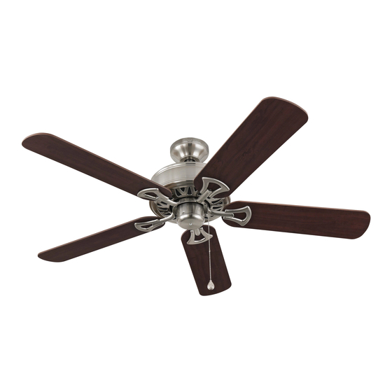
CLASSIC STYLE CEILING FAN
Purchase Date
1-800-643-0067, 8 a.m. - 6 p.m., EST, Monday - Thursday, 8 a.m. - 5
Lowes.com/harborbreeze
1
ITEM
#0076888
0077285
0079837
0080297
MODEL
#BDB52LW5N
BDB52ABZC5N
BDB52MBK5N
BDB52BNK5N
Español p. 19
LISTED
E192641
Advertisement
Table of Contents

Related Manuals for Harbor Breeze CLASSIC STYLE BDB52LW5N


Summary of Contents for Harbor Breeze CLASSIC STYLE BDB52LW5N
- Page 1 ITEM #0076888 0077285 0079837 0080297 CLASSIC STYLE CEILING FAN MODEL #BDB52LW5N Harbor Breeze® is a registered trademark of LF, LLC. All Rights Reserved. BDB52ABZC5N BDB52MBK5N BDB52BNK5N Español p. 19 LISTED ATTACH YOUR RECEIPT HERE E192641 Serial Number Purchase Date Questions, problems, missing parts? Before returning to your retailer, call our customer service department at 1-800-643-0067, 8 a.m.
-
Page 2: Table Of Contents
TABLE OF CONTENTS Safety Information ......................2 - 3 Package Contents .......................4 Hardware Contents ..........................5 Preparation ..........................5 Initial Installation ......................6 - 7 Downrod Style Fan Mounting ..................7 - 9 Closemount Style Fan Mounting ..................9 - 10 Wiring .........................11 - 12 Final Installation ......................12 - 14 Operation Instructions ....................14 - 15 Care and Maintenance ......................15 Troubleshooting........................16... -
Page 3: Safety Information
SAFETY INFORMATION WARNINGS To reduce the risk of fire, electrical shock, or personal injury, mount fan to outlet box marked "ACCEPTABLE FOR FAN SUPPORT OF 35 LB (15.9 KG) OR LESS" and use mounting screws provided with the outlet box. Most outlet boxes commonly used for the support of lighting fixtures are not acceptable for fan support and may need to be replaced. -
Page 4: Package Contents
PACKAGE CONTENTS PART DESCRIPTION QUANTITY PART DESCRIPTION QUANTITY Downrod Blade Screw (preassembled) Canopy Lock Washer Mounting Bracket (preassembled) Motor Housing Canopy Mounting Screw Plastic Locking Mechanism (preassembled) Blade Pin (preassembled) Blade Arm Clip (preassembled) Pull Chain Extension Motor Screw IMPORTANT REMINDER: You must use the (preassembled) parts provided with this fan for proper installation and safety. -
Page 5: Hardware Contents
HARDWARE CONTENTS (shown actual size) E3 Wire Connector Qty. 4 PREPARATION Before beginning assembly of product, make sure all parts are present. Compare parts with “Package Contents” list and diagrams on the previous page. If any part is missing or damaged, do not attempt to assemble the product. -
Page 6: Initial Installation
INITIAL INSTALLATION Turn off circuit breakers and wall switch to the fan supply line leads. DANGER: Failure to disconnect power supply prior to installation may result in serious injury or death. Determine mounting method to use. A. Downrod mount (normal or angled ceiling) B. - Page 7 INITIAL INSTALLATION Secure mounting bracket (C) to outlet box using screws, spring washers, and flat washers provided with the outlet box. *NOTE: It is very important that you use the proper hardware when installing the mounting bracket (C) as this will support the fan. IMPORTANT: If using the angle mount, make sure open end of mounting bracket (C) is installed facing the higher point of the ceiling.
- Page 8 DOWNROD STYLE FAN MOUNTING 2. Insert downrod (A) through canopy (B). Thread wires from motor housing (D) through downrod (A). Screw Depending on the length of downrod (A) you use, you may need to cut the lead wires back to simplify the wiring.
-
Page 9: Downrod Style Fan Mounting
DOWNROD STYLE FAN MOUNTING If you decided to cut back the lead wires in Step 4, strip 1/2 inch of insulation from end of white wire. Twist stripped ends of each strand of wire within the insulation with pliers (not included). Repeat Step 5 for black, blue (if applicable) and green wires. - Page 10 CLOSEMOUNT STYLE FAN MOUNTNG If neccessary, remove every other screw and lock washer from top of motor housing (D). (If there are only three screws and lock washers in top of motor housing (D), the other three screws and lock washers will be located in one of the hardware packs.) (Fig.
-
Page 11: Wiring
WIRING WARNING: To reduce the risk of fire, electrical shock, or personal injury, wire connectors provided with this fan are designed to accept only one 12-gauge house wire and two lead wires from the fan. If your house wire is larger than 12-gauge or there is more than one house wire to connect to the two fan lead wires, consult an... -
Page 12: Final Installation
WIRING Wrap electrical tape (not included) around each individual wire connector (AA) down to the wire. WARNING: Make sure no bare wire or wire strands are visible after making connections. Place green and white connections on opposite side of box from the black and blue (if applicable) connections. - Page 13 FINAL INSTALLATION Align the three blade screws (J), pre-installed on the blade arm (G), with the three holes in the blade (F). Press up on the blade arm (G) firmly so that the blade screws (J) come through the holes in the blade (F).
-
Page 14: Operation Instructions
FINAL INSTALLATION The pull chain extension (H) supplied in one of the hardware packs or a custom pull chain extension (not included) may be attached to fan pull chain. NOTE: This fan is remote control adaptable (remote control not included). OPERATION INSTRUCTIONS The pull chain located on the switch housing has four positions to control fan speed. -
Page 15: Care And Maintenance
OPERATION INSTRUCTIONS 2A. In warmer weather, setting the reverse switch in the DOWN position will result in downward airflow creating a wind chill effect. (Fig. 2A) 2B. In cooler weather, setting the reverse switch in the UP position will result in upward airflow that can help move stagnant, hot air off the ceiling area. -
Page 16: Troubleshooting
TROUBLESHOOTING WARNING: Before beginning work, shut off the power supply to avoid electrical shock. PROBLEM POSSIBLE CAUSE CORRECTIVE ACTION Fan does not move. 1. Reverse switch not engaged. 1. Push switch firmly either up or down. 2. Power is off or fuse is blown. 2. -
Page 17: Warranty
WARRANTY LIMITED LIFETIME WARRANTY: The distributor warrants this fan to be free from defects in workmanship and materials present at time of shipment from the factory for Lifetime limited from the date of purchase. This warranty applies only to the original purchaser. The distributor agrees to correct any defect at no charge or, at our option, replace the ceiling fan with a comparable or superior model. -
Page 18: Replacement Parts List
Blade G & J Blade Arm and Blade Screw Pull Chain Extension Motor Screw Lock Washer Canopy Mounting Screw Clip E3 Wire Connector Printed in China LI1205 Harbor Breeze® is a registered trademark of LF, LLC. All Rights Reserved. Lowes.com/harborbreeze...