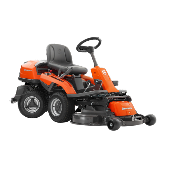
Husqvarna R 214TC Operator's Manual
Rider
Hide thumbs
Also See for R 214TC:
- Operator's manual (144 pages) ,
- Workshop manual (56 pages) ,
- Operator's manual (144 pages)

Related Manuals for Husqvarna R 214TC


Summary of Contents for Husqvarna R 214TC
- Page 1 Oper ator ′ s manual R 214TC Please r ead the operator’s manual carefully and make sure you E E E E n n n n g g g g l l l l i i i i s s s s h h h h...
-
Page 2: Key To Symbols
KEY TO SYMBOLS Symbols Noise emission to the environment according to the European Community’s Directive. The machine’s emission is These symbols are on the machine and in the instructions. specified in the Technical data chapter and on the label. WARNING! Careless or incorrect use can result in serious or fatal injury to the Clutch in operator or others. -
Page 3: Explanation Of Warning Levels
KEY TO SYMBOLS Explanation of warning levels Before and during reversing procedures, look behind you. The warnings are graded in three levels. WARNING! Starting instructions WARNING! Used if there is a risk of serious injury or death for the operator or damage to the surroundings if the instructions in the manual are not followed. -
Page 4: Table Of Contents
CONTENTS Contents Checking the engine’s cooling air intake ...... Checking and adjustment of the cutting unit’s ground KEY TO SYMBOLS pressure ............... Symbols ............... Checking the cutting unit’s parallelism ......Explanation of warning levels ........Adjusting the parallelism of the cutting unit ....CONTENTS Removing the cutting unit .......... -
Page 5: Introduction
Dear Customer, Thank you for choosing a Husqvarna Rider. Husqvarna Riders are built to a unique design with a front-mounted cutting unit and a patented articulated steering. Riders are designed for maximum efficiency even in small or confined areas. The closely grouped controls and pedal-operated hydrostatic transmission also contribute to the performance of this machine. -
Page 6: Service Journal
Service journal Pre-delivery service 12 Tell customer about: Needs and benefits of following the service 1 Charge the battery for 4 hours at max. 5 amp. schedule. 2 Fit steering wheel, seat and any optional Servicing and the influence of this journal on the equipment. -
Page 7: What Is What
WHAT IS WHAT? What is what on the ride-on mower 1 Speed limiter for driving forward 8 Cover lock 2 Speed limiter for reversing 9 Parking brake 3 Lifting lever for the cutting unit 10 Lock button for parking brake 4 Cutting height adjustment lever 11 Seat adjustment. -
Page 8: Safety Instructions
SAFETY INSTRUCTIONS Safety instructions • Remember that the driver is responsible for dangers or accidents. These instructions are for your safety. Read them carefully. • Never carry passengers. The machine is only intended to be used by one person. Insure your Rider •... -
Page 9: Driving On Slopes
SAFETY INSTRUCTIONS Driving on slopes • Never allow children or other persons not trained in the use of the machine to use or service it. Local laws may regulate the age of the user. Driving on slopes is one of the operations where the risk of the driver losing control of the machine or of it overturning is the greatest;... -
Page 10: Children
SAFETY INSTRUCTIONS Maintenance • Do not try to stabilize the machine by putting your foot on the ground. • Stop the engine. Prevent the engine from starting by • When cleaning the chassis, the machine may never be removing the ignition key before making any adjustments driven near verges or ditches. -
Page 11: Transport
SAFETY INSTRUCTIONS • Take care with battery maintenance. Explosive gases • Reduce the risk of fire by removing grass, leaves and form in the battery. Never perform maintenance on the other debris that may have fastened on the machine. battery while smoking or in the vicinity of open flames or Allow the machine to cool before putting it in storage. -
Page 12: Presentation
The speed of the machine is steplessly regulated with two that will give you great pleasure for many years. This pedals. Pedal (1) is used to drive forwards, and pedal (2) to operator’s manual describes R 214TC. drive backwards. WARNING! Make sure that branches do not obstruct the pedals when mowing under bushes. -
Page 13: Cutting Unit
R 214TC has a Combi 94 cutting unit model. The Combi-unit, equipped with a BioClip-plug, finely chops the cuttings to fertiliser. Without the BioClip-plug the unit works in the same way as a rear ejection unit. -
Page 14: Driving
Driving Before starting Start the engine • Read the safety instructions and information concerning 1 Make sure that the clutch control is depressed. the placement of controls and functions before starting. • Perform daily maintenance before starting as set out in the Maintenance schedule. -
Page 15: Starting The Engine With A Weak Battery
Driving Starting the engine with a weak 6 When the engine starts release the ignition key immediately back to neutral position. battery WARNING! Lead-acid batteries produce START START explosive gases. Avoid sparks, open flames and smoking close to batteries. Always wear protective glasses in the vicinity of batteries. -
Page 16: Driving The Rider
Driving Driving the Rider Stop the engine 1 Release the parking brake by first pressing down the Always park the machine on a level surface with the engine parking brake pedal and then releasing it. OFF. 1 Lift up the cutting unit by pulling the lever backwards to its locked position. -
Page 17: Maintenance
Maintenance Maintenance schedule The following is a list of the maintenance which should be conducted on the machine. For those points not described in this manual, visit an authorised service workshop. Daily At least once a Maintenance interval Maintenance maintenance year in hours before starting... -
Page 18: Cleaning
Maintenance Cleaning Right-hand fender Clean the machine directly after use. It is much easier to wash Remove the accelerator knob (1), screws (2 and 3), and off grass cuttings before they dry. remove the cover. Left-hand fender Remove the screws holding the wing cover (2) and lift off the cover. -
Page 19: Adjusting The Parking Brake
Maintenance Checking and adjusting of throttle 3 If necessary, the wires can be adjusted by tightening the adjuster nuts on each side of the steering collar. Do not wire over tighten the cables; they should only be drawn in towards the steering collar. Check that the engine responds to the throttle control and that 4 Unscrew the belt shields and the side protectors. -
Page 20: Replacement Of Fuel Filter
Maintenance Replacement of fuel filter Replacing the air filter Replace the fuel filter every 100 running hours (once per season) or more frequently if it is clogged. WARNING! The exhaust system is hot. Let it cool before starting to replace the air filter. If the engine seems to lack power or does not run smoothly this may be because the air filter is clogged. -
Page 21: Ignition System
Maintenance Ignition system Main fuse The main fuse is placed in a detachable holder under the The engine is equipped with an electronic ignition system. battery case’s cover, in front of the battery. Only the spark plug requires maintenance. Type: Flat pin, 15 A. For recommended spark plug, see Technical data. -
Page 22: Checking And Adjustment Of The Cutting Unit's Ground Pressure
Maintenance Checking and adjustment of the Adjusting the parallelism of the cutting unit’s ground pressure cutting unit To achieve the best cutting results the cutting unit should 1 Remove the front cover. follow the underlying surface without pressing too hard against it. -
Page 23: Removing The Cutting Unit
Maintenance Removing the cutting unit 7 To secure the cutting deck from spring back, place a wooden block between equipment frame and chassis. WARNING! Wear protective glasses when dismantling the cutting unit. The spring which tensions up the belt may break and cause personal injury. -
Page 24: Service Position For The Cutting Unit
Maintenance Service position for the cutting unit 7 Loosen on the cutting height stay and place in the holder. The cutting head can be placed in the service position to provide easy access for cleaning, repairs and servicing. In the service position the cutting unit is raised and locked in the vertical position. -
Page 25: Checking The Blades
Maintenance Checking the blades Assemble the parts in the reverse order. • The blade must be mounted with the angled ends pointing To achieve the best mowing results it is important that the up towards the cover. blades are undamaged and well-sharpened. Check that the blades’... -
Page 26: Lubrication
Lubrication Checking the engine’s oil level. Replacing the engine oil The engine oil should be changed the first time after 8 hours Check the oil level in the engine when the Rider stands running time. It should then be changed after every 100 hours horizontal with the engine switched off. -
Page 27: Changing The Oil Filter
Troubleshooting schedule Changing the oil filter Lubricating the belt adjuster The oil filter must be replaced after every 200 hours running The belt adjuster should be lubricated regularly using good time. Turn the old oil filter anti-clockwise to remove. If quality molybdenum disulphide grease*. - Page 28 Troubleshooting schedule Problem Cause There is no fuel in the fuel tank Faulty spark plug. Defective ignition cable. Engine does not start Dirt in the carburettor or fuel line Starter motor does not turn over the engine Defect safety switch Battery flat Bad contact between the cable and battery Lift lever for cutting unit in wrong position...
-
Page 29: Storage
Storage Winter storage Guard At the end of the season, or if the machine is going to stand There is a cover to protect your machine during storage or idle for more than 30 days, it should immediately be made transport. -
Page 30: Technical Data
Technical data Dimensions R 214TC Length with cutting unit, mm/ft 223 / 7,32 Length without cutting unit, mm/ft 194 / 6,36 Width with cutting unit, mm/ft 100-108 / 3,28-3,54 Width without cutting unit, mm/ft 89 / 2,92 Height, mm/ft 1070/3,52... -
Page 31: Ec Declaration Of Conformity
EC Declaration of Conformity (Applies to Europe only) Husqvarna AB, SE-561 82 Huskvarna, Sweden, tel.: +46 (0) 36 14 65 00, declares that the ride-on mower, Husqvarna R 214TC, from 2014’s serial numbers and onwards (the year is clearly stated on the rating plate followed by the serial number), complies with the requirements of THE COUNCIL’S DIRECTIVE:... - Page 32 Original instructions 1157317-26 ´®z+Y?h¶6S¨ ´®z+Y?h¶6S¨ 2015-02-25...