Lenovo ThinkServer RD630 Hardware Maintenance Manual
Machine types: 2577, 2579, 2592, 2593, 2594, and 2595
Hide thumbs
Also See for ThinkServer RD630:
- Benutzerhandbuch (210 pages) ,
- Hardware maintenance manual (208 pages) ,
- Manual d'utilisation (206 pages)
Table of Contents
Advertisement
Quick Links
Advertisement
Table of Contents

Related Manuals for Lenovo ThinkServer RD630


Summary of Contents for Lenovo ThinkServer RD630
- Page 1 Machine Types:...
- Page 2 Note: Read Me First Sixth Edition (March 2015) © Copyright Lenovo 2012, 2015.
-
Page 3: Table Of Contents
Contents Safety information ..Chapter 1. General information ..1 Chapter 2. Server setup road map . . . 5 Chapter 3. Product overview ..7 Chapter 6. - Page 4 Chapter 8. Getting information, help, and service ... . . Appendix A. Notices ..Chapter 7. Troubleshooting and diagnostics ... . . Index.
-
Page 5: Safety Information
Safety information Note: 製品をご使用になる前に、製品に付属の Documentation DVD に収録されているマルチリンガルの「安 全に正しくご使用いただくために」を読んで理解してください。 제품을 사용하기 전에 제품과 함께 제공되는 문서 DVD의 다국어 안전 지침을 주의 깊게 읽어보십시오. - Page 6 在使用本产品之前,请务必先阅读和了解产品附带的文档 DVD 中的多语言安全说明。 使用本產品之前,請務必閱讀並瞭解產品隨附的文件 DVD 上的多國語言版本安全資訊。 Important: Safety Information Safety Information...
- Page 7 Statement 1 DANGER Electrical current from power, telephone, and communication cables is hazardous. To avoid a shock hazard: Do not connect or disconnect any cables or perform installation, maintenance, or reconfiguration of this product during an electrical storm. Connect all power cords to a properly wired and grounded electrical outlet. Ensure that all power cord connectors are securely and completely plugged into receptacles.
- Page 8 Statement 3 CAUTION: When laser products (such as CD-ROMs, DVD drives, fiber optic devices, or transmitters) are installed, note the following: • Do not remove the covers. Removing the covers of the laser product could result in exposure to hazardous laser radiation. There are no serviceable parts inside the device. •...
- Page 9 Statement 6 CAUTION: If you install a strain-relief bracket option over the end of the power cord that is connected to the device, you must connect the other end of the power cord to a power source that is easily accessible in case it needs to be disconnected.
- Page 10 Statement 11 CAUTION: The following label indicates a potential heat hazard. Statement 12 DANGER Overloading a branch circuit is a potential fire hazard and a shock hazard under certain conditions. To avoid these hazards, ensure that your system electrical requirements do not exceed branch current ratings at the installation site.
- Page 11 Statement 16 CAUTION: To reduce the risk of electric shock or energy hazards: • This equipment must be installed by trained service personnel in a restricted-access location, as defined by your local electrical code and the latest edition of IEC 60950. •...
-
Page 12: Safety Inspection Guide
Statement 20 CAUTION: A lithium ion battery is provided. To avoid possible explosion, do not burn the battery. Replace the battery only with the Lenovo-approved part. Recycle or discard the battery as instructed by local regulations. Safety inspection guide... - Page 13 Grounding requirements...
-
Page 15: Chapter 1. General Information
Chapter 1. General information Introduction Hardware Maintenance Manual Hardware Maintenance Manual Note: Warranty and Support Information Warranty and Support Information Server documentation... - Page 16 Printed documents Read Me First Important Notices Rack Installation Instructions Note: Documentation DVD Note: Safety Information Warranty and Support Information Lenovo License Agreement User Guide...
- Page 17 Rack Installation Instructions ThinkServer Management Module User Guide Note: MegaRAID SAS Software User Guide Document only for trained service personnel Hardware Maintenance Manual...
-
Page 19: Chapter 2. Server Setup Road Map
Chapter 2. Server setup road map Rack Installation Instructions... -
Page 21: Chapter 3. Product Overview
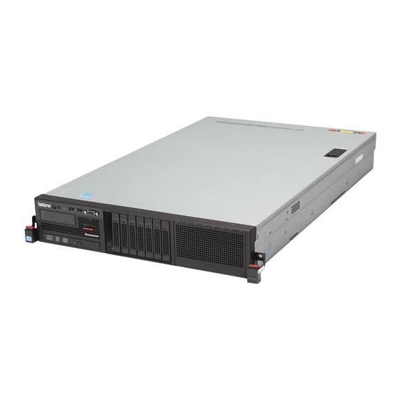
Chapter 3. Product overview Server package Note: Figure 1. Server package... - Page 22 Features Microprocessor Memory Power supply Note: System fans Internal drives Note:...
- Page 23 Expansion slots Input/Output (I/O) features Video subsystem Ethernet connectivity Reliability, availability, and serviceability...
- Page 24 Security features Note: Basic system management features ThinkServer Management Module User Guide...
- Page 25 Advanced system management features Note: ThinkServer Management Module User Guide Note: ThinkServer Management Module User Guide...
-
Page 26: Specifications
Specifications Dimensions Weight Environment Electrical input Software ThinkServer EasyStartup ThinkServer EasyStartup... - Page 27 ThinkServer EasyUpdate Firmware Updater Lenovo ThinkServer EasyManage BIOS and TMM update utilities RAID configuration utilities Remote management software ThinkServer Management Module User Guide Lenovo Rack Planner...
- Page 28 ThinkServer Smart Grid Technology Diagnostic programs Locations Machine type, model, and serial number label...
- Page 29 Note: Figure 2. Label on server models with 3.5-inch hard disk drives Figure 3. Label on server models with 2.5-inch hard disk drives...
- Page 30 Front view of the server Note: Front view of server models with 3.5-inch hard disk drives Figure 4. Front view of server models with 3.5-inch hard disk drives...
- Page 31 3.5-inch hard disk drive area Figure 5. 3.5-inch hard disk drive bay numbers (top view of the server) Rack handle (left) Rack handle (right) Rack Installation Instructions Pull-out information card Front panel Diagnostic panel Slim optical drive...
- Page 32 Front view of server models with 2.5-inch hard disk drives Figure 6. Front view of server models with 2.5-inch hard disk drives 2.5-inch hard disk drive area (right cage) 2.5-inch hard disk drive area (middle cage) Figure 7. Right cage with an EMI-protective panel Note: Pull-out information card...
- Page 33 Slim optical drive Rack handle (left) Rack handle (right) Rack Installation Instructions Diagnostic panel Front panel Front panel Figure 8. Front panel Power switch with power status LED...
- Page 34 Power status LED Color Description ID button with ID LED ID LED Color Description NIC 1 status LED NIC 2 status LED NIC status LED Color Description System error LED System error LED Color Description Front USB connectors VGA DB-15 connector...
-
Page 35: Diagnostic Module
Diagnostic module Intelligent Diagnostics Module (IDM) Figure 9. IDM panel Power supply error LED Ambient temperature limit LED System fan error LED... - Page 36 Memory module status LED Microprocessor status LED (also known as CPU status LED) Intelligent Diagnostics Module Premium (IDM Premium) Figure 10. IDM Premium panel...
- Page 37 System fan error LEDs Note: Figure 11. System fans...
- Page 38 CPU1 DIMM status LEDs CPU2 DIMM status LEDs Figure 12. DIMM status LEDs and DIMMs Ambient temperature limit LED Microprocessor status LEDs (also known as CPU status LEDs) Power supply error LEDs...
-
Page 39: Rear View Of The Server
Rear view of the server Figure 13. Rear view of the server Hot-swap redundant power supply 2 (available in some models) Hot-swap redundant power supply 1... - Page 40 PCI Express card area for cards on the riser card assembly 2 Figure 14. Riser card assembly 2 Notes: PCI Express Physical link Negotiable link width Supported card length and height card slot width...
- Page 41 PCI Express card area for cards on the riser card assembly 1 Figure 15. Riser card assembly 1 Notes: Physical link PCI Express Negotiable link width Supported card length and height card slot width...
- Page 42 5 8 9 Ethernet connectors (RJ-45) Notes: Figure 16. Ethernet status LEDs Ethernet status LED Color Status Description USB connectors VGA DB-15 connector Serial port...
-
Page 43: Server Components
ID LED ID LED Description Color Server components Note:... - Page 44 Components of server models with 3.5-inch hot-swap hard disk drives Figure 17. Components of server models with 3.5-inch hot-swap hard disk drives...
- Page 45 Components of server models with 2.5-inch hot-swap hard disk drives Figure 18. Components of server models with 2.5-inch hot-swap hard disk drives...
- Page 46 Notes: Self-service Optional-service FRU description Hot-swap hard disk drive status LEDs Figure 19. 3.5-inch hot-swap hard disk drive status LEDs...
-
Page 47: Raid Card
Figure 20. 2.5-inch hot-swap hard disk drive status LEDs Hard disk drive activity LED Hard disk drive RAID status LED Description RAID card Notes:... - Page 48 ThinkServer RAID 500 Adapter (also known as ThinkServer 9240-8i RAID 0/1 Adapter) Figure 21. ThinkServer RAID 500 Adapter Port 0 Port 1 RAID 5 key connector...
-
Page 49: Expander Card
ThinkServer RAID 700 Adapter (also known as ThinkServer 9260-8i SAS RAID Adapter) Figure 22. ThinkServer RAID 700 Adapter Ports 7-4 Ports 3-0 Board-to-board connector Expander card Note:... - Page 50 Figure 23. Expander card Hot-swap hard disk drive backplane Backplane for 3.5-inch hard disk drives...
- Page 51 Figure 24. Front view of the backplane for 3.5-inch hard disk drives Figure 25. Rear view of the backplane for 3.5-inch hard disk drives 8-pin power connector Optical drive power connector Mini-SAS ports 4-7 Mini-SAS ports 0-3...
- Page 52 Backplane for 2.5-inch hard disk drives Figure 26. Front view of the backplane for 2.5-inch hard disk drives Figure 27. Rear view of the backplane for 2.5-inch hard disk drives...
- Page 53 8-pin power connector Mini-SAS ports 4-7 Mini-SAS ports 0-3 Optical drive power connector Mini-SAS to mini-SAS signal cable connections Connecting cables from the RAID card to the backplane...
- Page 54 Figure 28. Connecting cables from the RAID card to the backplane Connecting cables from the RAID card to the expander card, and then from the expander card to the backplanes...
-
Page 56: System Board Components
Figure 29. Connecting cables from the expander card to the backplanes System board components... - Page 57 Figure 30. System board components...
- Page 58 Front panel connector Internal USB connector 1 Internal USB connector 2 Diagnostic module connector Front VGA connector SATA connector 0 Platform Controller Hub (PCH) System board battery Internal USB Type A connector 1 Internal USB Type A connector 2 TMM Premium connector TPM connector...
-
Page 59: System Board Jumpers And Switches
ThinkServer Management Module Riser card assembly 1 slot Riser card assembly 2 slot Redundant power supply connector 1 Redundant power supply connector 2 Backplane power connector 1 Backplane power connector 2 20 24 26 30 Memory slots Microprocessor socket 2 Microprocessor socket 1 21 23 25 27 28 31 System fan connectors... - Page 60 Figure 31. Default jumper setting...
- Page 61 Figure 32. System board jumpers and switches Attention: Clear CMOS jumper Note:...
- Page 62 Rack Installation Instructions TMM Enable/Disable jumper (also known as BMC Enable/Disable jumper)
- Page 63 System board switches Figure 33. System board switches BIOS recovery switch Clear password switch...
-
Page 64: System Board Leds
Rack Installation Instructions ME in force update switch Note: Rack Installation Instructions System board LEDs... - Page 65 Note: Figure 34. System board LEDs TMM status LED (also known as BMC status LED) TMM status LED Color Description System fan error LEDs...
-
Page 67: Chapter 4. Turning On And Turning Off The Server
Chapter 4. Turning on and turning off the server Turning on the server Turning off the server CAUTION: The power control button on the device and the power switch on the power supply do not turn off the electrical current supplied to the device. The device also might have more than one power cord. -
Page 69: Chapter 5. Configuring The Server
Chapter 5. Configuring the server Using the Setup Utility program Starting the Setup Utility program Viewing information in the Setup Utility program Main Advanced Processor Configuration Memory Configuration SATA/SAS Configuration... -
Page 70: Setup Utility Program Interface
Server Management System Information Setup Utility program interface Notes: Main menu Main Main Advanced menu Advanced Advanced... - Page 71 Notes: Enabled Disabled Advanced PCI Configuration ACPI Configuration Processor Configuration Memory Configuration Chipset Configuration Intel TXT (LT-SX) Configuration SATA/SAS Configuration USB Configuration Super IO Configuration Serial Port Console Redirection Network Stack Security menu Security Notes: Enabled Disabled Security Administrator Password User Password TPM/TCM Server Management menu...
-
Page 72: Setting The System Date And Time
Server Management Erase SEL System Information BMC Network Configuration Boot Options menu Boot Options Boot Manager menu Boot Manager Save & Exit menu Save & Exit Save & Exit Save & Exit Save Changes and Exit Save Changes and Reset Discard Changes and Exit Discard Changes Restore Defaults... -
Page 73: Using Passwords
Using passwords Setup Utility program password types Administrator password User password Note: Password considerations Notes: Setting, changing, or deleting a password... -
Page 74: Selecting A Startup Device
Security Administrator Password User Password Note: Selecting a startup device Note: Note: Boot Options Boot Option #1 Boot Option #5 Configuring the TPM function Security TPM/TCM ➙ TPM Support TPM Support Enabled TPM Support Enabled TPM State TPM State Enabled... -
Page 75: Setting The Mode Of The Ethernet Connector 0
Setting the mode of the Ethernet connector 0 Server Management BMC Network Configuration ➙ BMC LAN Share Setting Shared Dedicated Exiting the Setup Utility program Save & Exit ➙ Save Changes and Exit Save & Exit ➙ Discard Changes and Exit Save &... - Page 76 Updating (flashing) the BIOS Notes: Recovering from a BIOS update failure Note: Rack Installation Instructions...
- Page 77 Note: Using the ThinkServer EasyStartup program ThinkServer EasyStartup ThinkServer EasyStartup Features of the ThinkServer EasyStartup program...
-
Page 78: Starting The Thinkserver Easystartup Program
ThinkServer EasyStartup Starting the ThinkServer EasyStartup program User Guide ThinkServer EasyStartup Note: ThinkServer EasyStartup Next Agree Notes: Compatibility notes User Guide... - Page 79 Home Compatibility notes User Guide Hardware list Configure RAID Install operating system Download drivers ThinkServer EasyStartup Note: About Using the ThinkServer EasyStartup program on a Windows operating system ThinkServer EasyStartup ThinkServer EasyStartup Notes: ThinkServer EasyStartup...
-
Page 80: Configuring Raid
ThinkServer EasyStartup ThinkServer EasyStartup ThinkServer EasyStartup Note: Configuring RAID About RAID RAID 0... - Page 81 RAID 1 RAID 5 RAID 10 RAID 50 Note: MegaRAID SAS Software User Guide Configuring RAID using the ThinkServer EasyStartup program...
-
Page 82: Configuring The Advanced Sata Or Sas Hardware Raid
ThinkServer EasyStartup ThinkServer EasyStartup ThinkServer EasyStartup Configuring the advanced SATA or SAS hardware RAID ThinkServer EasyStartup ThinkServer EasyStartup Note: ThinkServer EasyStartup MegaRAID SAS Software User Guide Configuring the Ethernet controllers... - Page 83 Updating the firmware Using the Firmware Updater program Note: Using the Lenovo ThinkServer EasyManage program...
-
Page 85: Chapter 6. Installing, Removing, Or Replacing Hardware
Chapter 6. Installing, removing, or replacing hardware Guidelines Precautions... - Page 86 Handling static-sensitive devices Attention: Notes: Note:...
- Page 87 System reliability guidelines Working inside the server with the power on Attention: Removing the server cover Attention:...
- Page 88 Note: Rack Installation Instructions Figure 35. Pressing the release button...
-
Page 89: Removing And Reinstalling The Front Bezel
Note: Figure 36. Removing the server cover Attention: Removing and reinstalling the front bezel Attention: Notes:... - Page 90 Figure 37. Removing the front bezel Figure 38. Installing the front bezel Installing, removing, or replacing hardware...
-
Page 91: Removing And Reinstalling The Rack Handles
Notes: Attention: Removing and reinstalling the rack handles Attention: Note: Figure 39. Removing the rack handles... -
Page 92: Removing And Reinstalling The Cooling Shroud
Figure 40. Installing the rack handles Removing and reinstalling the cooling shroud Attention: Note:... - Page 93 Rack Installation Instructions Figure 41. Removing the cooling shroud Note: Figure 42. Installing the cooling shroud...
-
Page 94: Removing And Reinstalling The Left Cage
Attention: Removing and reinstalling the left cage Attention: Note: Note: Rack Installation Instructions... - Page 95 Figure 43. Removing the left cage Figure 44. Sliding the left cage into the chassis...
-
Page 96: Installing Or Removing A Memory Module
Figure 45. Installing the screws to secure the left cage Installing or removing a memory module Note: Memory module installation rules... - Page 98 Figure 46. Memory slots on the system board Note:...
- Page 99 Note: Figure 47. CPU1 DIMMs Table 1. Memory module installation rules for servers with one microprocessor CPU1 DIMM Note:...
- Page 100 Note: Figure 48. CPU1 DIMMs and CPU2 DIMMs Table 2. Memory module installation rules for servers with two microprocessors CPU1 DIMM CPU2 DIMM Note:...
- Page 101 Installing a memory module Attention: Notes: Rack Installation Instructions Figure 49. Opening the retaining clips of the memory slot Note:...
- Page 102 Note: Figure 50. Installing a memory module What to do next: Removing a memory module Attention: Note: Rack Installation Instructions...
-
Page 103: Installing Or Removing An Ethernet Card
Figure 51. Removing a memory module What to do next: Installing or removing an Ethernet card Note: Installing an Ethernet card Attention: Notes:... - Page 104 Rack Installation Instructions Note: Figure 52. Removing a PCI Express card slot bracket Note: Note:...
- Page 105 Figure 53. Removing the full-height bracket from the PCI Express card Figure 54. Installing the low-profile bracket to the PCI Express card...
- Page 106 Figure 55. Installing an Ethernet card What to do next: Note: ThinkServer EasyStartup ThinkServer EasyStartup Removing an Ethernet card Attention:...
- Page 107 Notes: Rack Installation Instructions Note: Note: Figure 56. Removing an Ethernet card...
- Page 108 What to do next: Installing or removing the ThinkServer RAID 500 Upgrade Key for Advanced RAID Installing the TR 500 Key Attention: Attention: Note: Rack Installation Instructions Note:...
- Page 109 Note: Figure 57. Installing the TR 500 Key What to do next: MegaRAID SAS Software User Guide Removing the TR 500 Key Attention: Attention: Notes:...
-
Page 110: Installing Or Removing The Thinkserver Raid 700 Battery
Rack Installation Instructions Note: Figure 58. Removing the TR 500 Key What to do next: MegaRAID SAS Software User Guide Installing or removing the ThinkServer RAID 700 Battery... - Page 111 Attention: Installing the TR 700 Battery Attention: Note: Rack Installation Instructions Note:...
- Page 112 Notes: Figure 59. Installing the TR 700 Battery What to do next: Removing the TR 700 Battery Attention: Notes:...
-
Page 113: Installing Or Removing The Expander Card
Rack Installation Instructions Note: Figure 60. Removing the TR 700 Battery What to do next: Installing or removing the expander card... - Page 114 Notes: Installing the expander card Attention: Attention: Notes: Rack Installation Instructions...
- Page 115 Note: Figure 61. Removing a PCI Express card slot bracket Note: Figure 62. Installing the expander card...
- Page 116 What to do next: Note: Removing the expander card Attention: Attention: Notes: Rack Installation Instructions...
- Page 117 Note: Figure 63. Removing the expander card What to do next: Installing or removing the ThinkServer Management Module Premium...
- Page 118 Installing the TMM Premium Attention: Notes: Rack Installation Instructions...
- Page 119 Note: Figure 64. Installing the TMM Premium What to do next: ThinkServer Management Module User Guide Removing the TMM Premium Attention:...
- Page 120 Notes: Rack Installation Instructions Figure 65. Removing the TMM Premium...
- Page 121 What to do next: Installing or removing the ThinkServer Trusted Platform Module Installing the TPM Attention: Notes: Rack Installation Instructions Note:...
- Page 122 Figure 66. Installing the TPM What to do next: Removing the TPM Attention:...
- Page 123 Notes: Rack Installation Instructions...
- Page 124 Note: Figure 67. Removing the TPM What to do next: Installing or replacing a hot-swap redundant power supply Attention:...
- Page 125 CAUTION: Hazardous moving parts. Keep fingers and other body parts away. CAUTION: Never remove the cover on a power supply or any part that has the following label attached. Hazardous voltage, current, and energy levels are present inside any component that has this label attached.
- Page 126 Figure 68. Removing the protective shield for the power supply bay Note:...
- Page 127 Figure 69. Removing a hot-swap redundant power supply Figure 70. Installing a hot-swap redundant power supply...
-
Page 128: Installing Or Replacing A Heat Sink
Installing or replacing a heat sink Attention: CAUTION: The heat sink might be very hot. Turn off the server and wait three to five minutes to let the server cool before removing the server cover. Note: Rack Installation Instructions... - Page 129 Note: Figure 71. Removing the screws that secure the heat sink Notes:...
-
Page 130: Installing Or Replacing The Microprocessor
Figure 72. Installing the screws to secure the heat sink What to do next: Installing or replacing the microprocessor Installing the second microprocessor Attention:... - Page 131 CAUTION: Turn off the server and wait three to five minutes to let the server cool before removing the server cover. Notes: Rack Installation Instructions Note: Figure 73. Opening the handles...
- Page 132 Note: Figure 74. Opening the microprocessor retainer Figure 75. Do not touch the pins...
- Page 133 Note: Figure 76. Installing the microprocessor Note: Figure 77. Removing the microprocessor socket cover...
-
Page 134: Replacing The Microprocessor
Note: Figure 78. Securing the microprocessor in the socket What to do next: Replacing the microprocessor Attention: CAUTION: The heat sink and microprocessor might be very hot. Turn off the server and wait three to five minutes to let the server cool before removing the server cover. - Page 135 Notes: Rack Installation Instructions Note: Figure 79. Opening the handles...
- Page 136 Figure 80. Opening the microprocessor retainer Notes: Figure 81. Removing the microprocessor...
- Page 137 Figure 82. Do not touch the pins Note: Figure 83. Installing the microprocessor...
-
Page 138: Installing Or Replacing The Optical Drive
Note: Figure 84. Securing the microprocessor in the socket What to do next: Installing or replacing the optical drive Attention: CAUTION: When laser products (such as CD-ROMs, DVD drives, fiber optic devices, or transmitters) are installed, note the following: • Do not remove the covers. Removing the covers of the laser product could result in exposure to hazardous laser radiation. - Page 139 DANGER Some laser products contain an embedded Class 3A or Class 3B laser diode. Note the following: Laser radiation when open. Do not stare into the beam, do not view directly with optical instruments, and avoid direct exposure to the beam. Notes: Rack Installation Instructions...
- Page 140 Figure 85. Removing the optical drive for server models with 3.5-inch hard disk drives Figure 86. Removing the optical drive for server models with 2.5-inch hard disk drives...
- Page 141 Figure 87. Installing the optical drive retaining bracket...
- Page 142 Figure 88. Installing the optical drive for server models with 3.5-inch hard disk drives Figure 89. Installing the optical drive for server models with 2.5-inch hard disk drives...
- Page 143 Figure 90. Connecting cables to the rear of the optical drive What to do next: Installing or replacing a hot-swap hard disk drive Attention: Attention:...
- Page 144 Notes: Figure 91. Opening the handle of a 3.5-inch hot-swap hard disk drive or dummy tray...
- Page 145 Figure 92. Opening the handle of a 2.5-inch hot-swap hard disk drive or dummy tray Figure 93. Removing the 3.5-inch hot-swap hard disk drive or dummy tray...
- Page 146 Figure 94. Removing the 2.5-inch hot-swap hard disk drive or dummy tray Note: Figure 95. Installing the 3.5-inch hot-swap hard disk drive...
- Page 147 Figure 96. Installing the 2.5-inch hot-swap hard disk drive What to do next: Replacing the hot-swap hard disk drive backplane Note: Replacing the backplane for 3.5-inch hard disk drives Attention:...
- Page 148 Notes: Rack Installation Instructions Figure 97. Releasing the backplane for 3.5-inch hard disk drives...
- Page 149 Figure 98. Removing the backplane for 3.5-inch hard disk drives Note: Figure 99. Installing the backplane for 3.5-inch hard disk drives...
- Page 150 Figure 100. Securing the backplane for 3.5-inch hard disk drives What to do next: Replacing the backplane for 2.5-inch hard disk drives Attention: Notes:...
- Page 151 Rack Installation Instructions Figure 101. Removing the backplane for 2.5-inch hard disk drives Note:...
-
Page 152: Replacing The Riser Card Assembly 1
Figure 102. Installing the backplane for 2.5-inch hard disk drives What to do next: Replacing the riser card assembly 1 Attention: Note:... - Page 153 Rack Installation Instructions Figure 103. Lifting the riser card assembly 1 off the chassis...
-
Page 154: Replacing The Riser Card Assembly 2
Note: Figure 104. Installing the riser card assembly 1 What to do next: Replacing the riser card assembly 2 Attention: Note:... - Page 155 Rack Installation Instructions Note: Figure 105. Lifting the riser card assembly 2 off the chassis...
-
Page 156: Replacing The Raid Card
Note: Figure 106. Installing the riser card assembly 2 What to do next: Replacing the RAID card Attention: Attention:... - Page 157 Notes: Rack Installation Instructions Note: Figure 107. Removing the RAID card Note:...
-
Page 158: Replacing The Front Panel Board
Figure 108. Installing the RAID card What to do next: Note: Replacing the front panel board... - Page 159 Notes: Replacing the front panel board for server models with 3.5-inch hard disk drives Attention: Rack Installation Instructions Figure 109. Removing the front panel board for server models with 3.5-inch hard disk drives...
- Page 160 Note: Figure 110. Installing the front panel board for server models with 3.5-inch hard disk drives What to do next: Replacing the front panel board for server models with 2.5-inch hard disk drives Attention: Rack Installation Instructions...
- Page 161 Figure 111. Removing the front panel board from the left cage of server models with 2.5-inch hard disk drives Note: Figure 112. Installing the front panel board in the left cage of server models with 2.5-inch hard disk drives...
-
Page 162: Diagnostics
What to do next: Replacing the diagnostic module Note: Replacing the diagnostic module for server models with 3.5-inch hard disk drives Attention: Rack Installation Instructions... - Page 163 Figure 113. Removing the diagnostic module for server models with 3.5-inch hard disk drives Figure 114. Installing the diagnostic module for server models with 3.5-inch hard disk drives...
- Page 164 What to do next: Replacing the diagnostic module for server models with 2.5-inch hard disk drives Attention: Rack Installation Instructions Figure 115. Removing the diagnostic module from the left cage of server models with 2.5-inch hard disk drives...
-
Page 165: Replacing A System Fan
Figure 116. Installing the diagnostic module into the left cage of server models with 2.5-inch hard disk drives What to do next: Replacing a system fan Attention: CAUTION: Hazardous moving parts. Keep fingers and other body parts away. Note:... - Page 166 Note: Figure 117. Removing the system fan...
-
Page 167: Replacing The System Board Battery
Figure 118. Installing the system fan What to do next: Replacing the system board battery Attention: DANGER Danger of explosion if battery is incorrectly replaced. When replacing the lithium coin cell battery, use only the same or an equivalent type that is recommended by the manufacturer. - Page 168 • Heat to more than 100°C (212°F) • Repair or disassemble Dispose of the battery as required by local ordinances or regulations. The following statement applies to users in the state of California, U.S.A. California Perchlorate Information: Products containing manganese dioxide lithium coin cell batteries may contain perchlorate. Perchlorate Material - special handling may apply, Seehttp://www.dtsc.ca.gov/hazardouswaste/perchlorate Note:...
-
Page 169: Replacing The System Board
Figure 120. Installing the system board battery What to do next: Replacing the system board Attention: Note: CAUTION: Hazardous moving parts. Keep fingers and other body parts away. CAUTION: The heat sinks and microprocessors might be very hot. Turn off the server and wait three to five minutes to let the server cool before removing the server cover. - Page 170 Note: Rack Installation Instructions Figure 121. Removing the system fan cage with system fans...
- Page 171 Figure 122. Removing the power supply cooling shroud...
- Page 172 Figure 123. Removing the screws that secure the system board...
- Page 173 Note: Figure 124. Removing the system board Figure 125. Installing the system board...
- Page 174 Figure 126. Installing the screws to secure the system board...
- Page 175 Notes: Figure 127. Securing the microprocessor retainer Figure 128. Installing the microprocessor socket cover...
- Page 176 Figure 129. Installing the power supply cooling shroud Figure 130. Installing the system fan cage with system fans...
- Page 177 What to do next: Note: Completing the parts replacement Reinstalling the server cover and reconnecting cables Attention: Attention: Note:...
- Page 178 Figure 131. Cable routing...
- Page 179 Figure 132. Installing the server cover Figure 133. Closing the server cover completely Rack Installation Instructions...
- Page 180 Attention: Note: Updating the server configuration...
- Page 181 Chapter 7. Troubleshooting and diagnostics Troubleshooting procedure Viewing the status and diagnostic LEDs...
- Page 182 Using a diagnostic program Continue Accept Viewing the system event log ThinkServer Management Module User Guide Basic troubleshooting tables ThinkServer EasyStartup program problems Note:...
-
Page 183: Optical Drive Problems
Symptom Action ThinkServer EasyStartup ThinkServer EasyStartup Optical drive problems Notes: Action Symptom... -
Page 184: Hard Disk Drive Problems
Symptom Action Hard disk drive problems Notes: Symptom Action... -
Page 185: Memory Module Problems
Symptom Action Memory module problems Notes: Symptom Action... - Page 186 Symptom Action Keyboard, mouse, and USB device problems Symptom Action...
-
Page 187: And Service
Chapter 8. Getting information, help, and service Information resources Using the documentation Hardware Maintenance Manual ThinkServer Web site Lenovo Support Web site... -
Page 188: Help And Service
Help and service Before you call Calling for service Problem determination Hardware repair Engineering Change management... - Page 189 Warranty and Support Information Using other services Warranty Purchasing additional services...
-
Page 191: Appendix A. Notices
Appendix A. Notices Lenovo (United States), Inc. 1009 Think Place - Building One Morrisville, NC 27560 U.S.A. Attention: Lenovo Director of Licensing... - Page 192 Trademarks Important notes Particulate contamination Attention:...
-
Page 193: Recycling Information
Table 3. Limits for particulates and gases Contaminant Limits Method of Testing General Ventilation Air-Cleaning Devices for Removal Efficiency by Particle Size Environmental conditions for process measurement and control systems: Airborne contaminants Polyvinyl Chloride (PVC) cable and cord notice WARNING: Wash hands after handling Recycling information Battery return program... - Page 194 Battery recycling information for the European Union Notice: Requirement for batteries containing perchlorate Important WEEE information...
- Page 195 German Ordinance for Work gloss statement Export classification notice Electronic emission notices User Guide ENERGY STAR model information...
-
Page 197: Index
Index...