Spirit XBR25 Owner's Manual
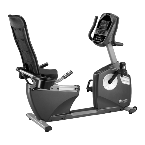
Spirit fitness bike owner's manual
Hide thumbs
Also See for XBR25:
- Owner's manual (34 pages) ,
- Service manual (20 pages) ,
- Owner's manual (27 pages)

Related Manuals for Spirit XBR25


Summary of Contents for Spirit XBR25
- Page 1 FITNESS BIKE O O O O WNER’S MANUAL WNER’S MANUAL WNER’S MANUAL WNER’S MANUAL PLEASE CAREFULL Y READ THIS ENTIRE MANUAL BEFORE OPERATING YOUR NEW FITNESS BIKE! XR326-AB16_1406(SL)B...
-
Page 2: Table Of Contents
Table Of Contents Important Safety Instructions Important Electrical Instructions Important Operation Instructions Assembly Instructions Features Console Operation Programmable Features Heart Rate Information General Maintenance Exploded View Diagram Parts list ATTENTION This fitness bike is intended for residential use only and is warranted for this application. -
Page 3: Important Safety Instructions
Important Safety Instructions When using an electrical appliance, basic precautions should always be followed, including the following: WARNING - Read all instructions before using this appliance. DANGER - To reduce the risk of electric shock disconnect your fitness bike from the electrical outlet prior to cleaning and/or service work. -
Page 4: Important Electrical Instructions
Important Electrical Instructions WARNING! NEVER remove any cover without first disconnecting AC power. If voltage varies by ten percent (10%) or more, the performance of your fitness bike may be affected. Such conditions are not covered under your warranty. If you suspect the voltage is low, contact your local power company or a licensed electrician for proper testing. -
Page 5: Assembly Instructions
Assembly Instructions Pre-Assembly 1. Using a razor knife (Box Cutter), cut the banding straps that wrap around the carton. Reach under the bottom edge of the carton and pull it away from the cardboard underneath, separating the staples that join the two together. Lift the box over the unit and unpack. 2. - Page 6 STEP 1: Rear Stabilizer & Seat Back Attach the Rear Stabilizer (7) to the Main Frame (1) with the two Carriage Bolts (65), two Flat Washers (84) and two Cap Nuts (191).Tighten completely with the Wrench (112). Attach the Seat Back (5) to the Seat Carriage (4) of the main frame. Slide a Hex Head Bolt (67) and a Hex Head Bolt (142) through each side, then attach a Flat Washer (77) and a Nyloc Nut (89) to each bolt.
- Page 7 STEP 2: Console Mast Slide the Computer Cable (44) through the bottom of the Console Mast Cover (31) and then the bottom of the Console Mast (2). Make sure the Console Mast Cover is correctly oriented (see illustration). Install the Console Mast (2) into the receiving tube (make sure not to pinch cable (44); damage to the electronics could occur) of the Main Frame (1).
- Page 8 STEP 3: Seat & Handle Bar Install the Seat (61) on the Seat Carriage (4) with four Phillips Head Screws (98).Tighten with the Phillips Head Screw Driver (114). Attach the Seat Handle Bar (6) to the Seat Carriage (4) with the four Hex Head Bolts (71), four Flat Washers (77), and four Nyloc Nuts (89).Tighten with the Wrenches provided (112 &...
- Page 9 STEP 4: Plastic Parts Remove the Button Head Socket Screws holding the clamps of the left Release Lever (40) by using the Allen Wrench (115). Install the Release Lever (40) onto the Handle Bar Seat (6) just behind the Hand pulse sensors on the left side (when facing the front of the bike). Install it at an angle that allows easy access for use, then reinsert and tighten the socket screws removed earlier.
-
Page 10: Features
Product Features Transportation The fitness bike is equipped with two transport wheels that are engaged when the rear of the XBR Series Fitness bike is lifted. Seat Adjustability There is a cable activated hand lever on left side of the seat for convenient adjustments of the seat location. -
Page 11: Console Operation
Operation Of Your Console GETTING FAMILIAR WITH THE CONTROL PANEL Large LCD with scrolling feedback and scrolling message center Swivel Fan to keep you cool Innovative programs offer a variety of work-outs Convenient cargo compartment for Easy-Touch keys, phone, or Control Buttons MP3 player Power... -
Page 12: Quick Start
Quick Start This is the quickest way to start a workout. After the console powers up you just press the Start key to begin, this will initiate the Quick Start mode. In Quick Start the Time will count up from zero and the workload may be adjusted manually by pressing the Level Up/Down buttons. - Page 13 Program Keys The Program Keys are used to preview each program. When you first turn the console on you may press each program key to preview what the program profile looks like. If you decide that you want to try a program, press the corresponding program key and then press the Enter key to select the program and enter into the data-setting mode.
-
Page 14: Programmable Features
Programmable Features Manual The Manual program works as the name implies, manually. This means that you control the workload and not the computer. To start the Manual program, follow the instructions below or just press the Manual button, then the Enter button and follow the directions in the Message Center. -
Page 15: Preset Programs
Preset Programs The fitness bike has five different programs that have been designed for a variety of workouts. These five programs have factory preset work level profiles for achieving different goals. Hill RESISTANCE This program follows a triangle or pyramid type of gradual progression from approximately 10% of maximum effort (the level that you chose before starting this program) up to a maximum effort which lasts for 10% of the total workout time,... - Page 16 Programming Preset Programs 1. Select the desired program button then press the Enter key. 2. The Message Center will ask you to enter your Age. You may adjust the age setting, using the Level Up/Down keys, then press the Enter key to accept the new number and proceed on to the next screen.
-
Page 17: Heart Rate Information
Heart Rate Information The old motto, “no pain, no gain”, is a myth that has been overpowered by the benefits of exercising comfortably. A great deal of this success has been promoted by the use of heart rate monitors. With the proper use of a heart rate monitor, many people find that their usual choice of exercise intensity was either too high or too low and exercise is much more enjoyable by maintaining their heart rate in the desired benefit range. -
Page 18: Rate Of Perceived Exertion
Rate Of Perceived Exertion Heart rate is important but listening to your body also has a lot of advantages. There are more variables involved in how hard you should workout than just heart rate. Your stress level, physical health, emotional health, temperature, humidity, the time of day, the last time you ate and what you ate, all contribute to the intensity at which you should workout. - Page 19 Using Heart Rate Transmitter (Sold Separately) Wearing The Chest Strap Attach the transmitter to the elastic strap using the locking parts. Adjust the strap as tightly as possible as long as the strap is not too tight to remain comfortable. Position the transmitter with the logo centered in the middle of your torso facing away from your chest (some people must position the transmitter slightly left of center).
- Page 20 Heart Rate Program Operation Note: You must wear a heart rate transmitter strap (sold separately) for this program. The Heart Rate program default setting is 60% of your projected maximum heart rate. The 60-80% range is more conducive for fat loss goals and 81-100% ranges are generally used for cardiovascular conditioning goals and high intensity interval training.
-
Page 21: General Maintenance
General Maintenance 1. Wipe down all areas in the sweat path with a damp cloth after each workout. 2. If a squeak, thump, clicking or rough feeling develops the main cause is most likely one of two reasons: The hardware was not sufficiently tightened during assembly. All bolts that were installed during assembly need to be tightened as much as possible. -
Page 22: Exploded View Diagram
Exploded View Diagram... -
Page 23: Parts List
Parts List Part Number Part Description Qty per unit Main Frame Console Mast Mast Handle bar Assembly Seat Carriage Seat Back Bracket Seat Handle Bar Rear Stabilizer Crank Axle Seat Wheel Adjustment Plate (L) Seat Wheel Adjustment Plate (R) Idler Wheel Assembly Seat Stop Axle Seat Position Latch Backing Plate... - Page 24 Part Number Part Description Qty per unit Handgrip End Cap Bottom Cover Round Disk Rear Shroud (L) Rear Shroud (R) Drink Bottle Holder (R) Drink Bottle Holder (L) Release Lever Transformer Power Cord (ONLY 220V) 300m/m_Hand Pulse Sensor Assembly W/Cable Gear Motor 750m/m_Computer Cable 2100m/m_Hand Pulse Sensor Assembly W/Cable...
- Page 25 Part Number Part Description Qty per unit 3/8" × 7T_Nyloc Nut 1/4" × 8T_Nyloc Nut 5/16" × 6T_Nyloc Nut M6 × 38m/m_Socket Head Cap Bolt 5/16" × 3/4"_Hex Head Bolt M5 × 12m/m_Flat Head Socket Screw Ø3 × 20m/m_Tapping Screw M6 ×...