Mitsubishi Electric MSH-18NV Service Manual
Split-type, heat pump air conditioners wireless type
Hide thumbs
Also See for MSH-18NV:
- Service manual (81 pages) ,
- Operating instructions manual (28 pages) ,
- Operating instructions manual (28 pages)
Table of Contents
Advertisement
SPLIT-TYPE, HEAT PUMP AIR CONDITIONERS
SERVICE MANUAL
Wireless type
Model
MSH-18NV -
MSH-18NV -
E4
•Refer to the Service Manual OB185 REVISED EDITION C when MSH-18NV-
MXZ-32NV-
or MXZ-32NV-
E1
•Refer to the Service Manual OB227 REVISED EDITION-B when MSH-18NV-
MXZ-32RV-
as multi system units.
E1
· MUH-18NV -
( WH )
E4
CONTENTS
1. TECHNICAL CHANGES ····································2
2. PART NAMES AND FUNCTIONS······················2
3. SPECIFICATION·················································4
4. OUTLINES AND DIMENSIONS ························ 5
5. WIRING DIAGRAM ············································6
6. REFRIGERANT SYSTEM DIAGRAM ················7
7. PERFORMANCE CURVES ································8
8. MICROPROCESSOR CONTROL ····················10
9. SERVICE FUNCTIONS ····································19
10. TROUBLESHOOTING······································21
11. DISASSEMBLY INSTRUCTIONS·····················30
12. PARTS LIST······················································34
13. OPTIONAL PARTS···········································37
as multi system units.
E2
Revision:
Information for connecting MSH-18NV-
MXZ-32RV-
was described.
E1
TROUBLESHOOTING has been modified.
is connected with
E4
is connected with
E4
with
E4
No. OB229
REVISED EDITION-A
E4
Advertisement
Table of Contents

Related Manuals for Mitsubishi Electric MSH-18NV


Summary of Contents for Mitsubishi Electric MSH-18NV
-
Page 1: Table Of Contents
9. SERVICE FUNCTIONS ····································19 10. TROUBLESHOOTING······································21 11. DISASSEMBLY INSTRUCTIONS·····················30 12. PARTS LIST······················································34 13. OPTIONAL PARTS···········································37 •Refer to the Service Manual OB185 REVISED EDITION C when MSH-18NV- is connected with MXZ-32NV- or MXZ-32NV- as multi system units. •Refer to the Service Manual OB227 REVISED EDITION-B when MSH-18NV-... -
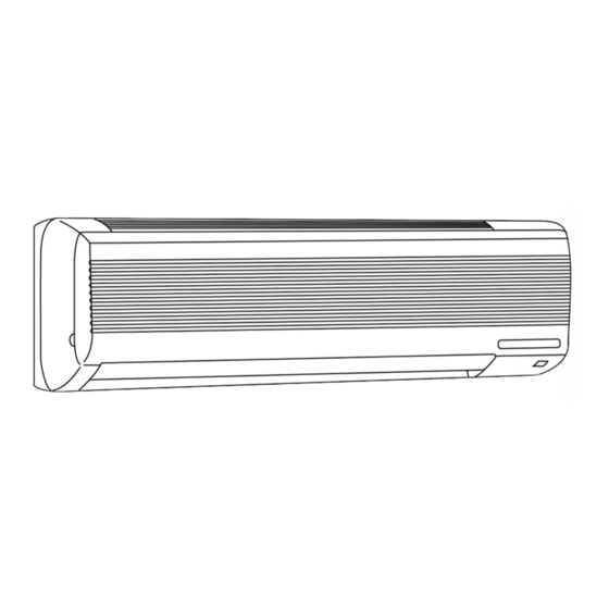
Page 2: Technical Changes
TECHNICAL CHANGES MSH-18NV- became possible the connection to MXZ-32RV- as multi system units. PART NAMES AND FUNCTIONS INDOOR UNIT MSH-18NV - Front panel (When the grille is open) -
Page 3: Outdoor Unit
OUTDOOR UNIT MUH-18NV - Air inlet (back and side) Piping Drainage hose Air outlet Drain outlet REMOTE CONTROLLER MSH-18NV - Signal transmitting section Operation display section OPERATE/STOP (ON/OFF)button OPERATION SELECT button TEMPERATURE buttons VANE CONTROL button FAN SPEED CONTROL button... -
Page 4: Specification
SPECIFICATION wRefer to the Service Manual OB185 REVISED EDITION C when MSH-18NV- is connected with MXZ-32NV- or MXZ-32NV- as multi system units. wRefer to the Service Manual OB227 REVISED EDITION-B when MSH-18NV- is connected with MXZ-32RV- as multi system units. -
Page 5: Outlines And Dimensions
OUTLINES AND DIMENSIONS Unit: mm MSH-18NV - INDOOR UNIT 4holes 11 20 Indoor unit Wall hole [75 Installation plate 1015 Installation plate Liquid line [8-0.5m Gas line [12-0.43m Air in Insulation [50 O.D [28 I.D Drain hose [16 Air out... -
Page 6: Wiring Diagram
WIRING DIAGRAM MSH-18NV - MODEL WIRING DIAGRAM INDOOR UNIT TO OUTDOOR UNIT RT12 CONNECTING HIC1 IC141 12VDC 220-240V~ CN201 CN211 TRANS POWER SUPPLY CN CN RT11 ELECTRONIC CONTROL P.C BOARD 101 102 CORD ~/N 220-240V 50Hz GRN/YLW DISPLAY RECEIVER CIRCUIT BREAKER P.C.BOARD... -
Page 7: Refrigerant System Diagram
REFRIGERANT SYSTEM DIAGRAM MSH-18NV - MUH-18NV - OUTDOOR UNIT INDOOR UNIT Reversing valve Refrigerant pipe [15.88 (4- way valve) (Option) Muffler (with heat insulator) Indoor coil Indoor thermistor Strainer Stop valve RT12 heat Outdoor exchanger (with service port) Distributor heat... -
Page 8: Performance Curves
PERFORMANCE CURVES MSH-18NV - The standard data contained in these specifications apply only to the operation of the air conditioner under normal conditions, since operating conditions vary according to the areas where these units are installed. The following information has been provided to clarify the operating characteristics of the air conditioner under the conditions indicated by the performance curve. -
Page 9: Heat Operation
28.0 25.9 23.7 21.6 19.4 17.2 15.1 12.9 NOTE:The above curves are for the heating operation without any frost. OUTDOOR LOW PRESSURE AND OUTDOOR UNIT CURRENT COOL operation 1 1 Both indoor and outdoor unit are under the same temperature/humidity condition. Relative humidity(%) Dry-bulb temperature 2 2 Air flow should be set at MAX. -
Page 10: Microprocessor Control
MICROPROCESSOR CONTROL MSH-18NV - WIRELESS REMOTE CONTROLLER Once the operation mode are set, the same operation mode can be repeated by simply turning the OPERATE/STOP (ON/OFF) button ON. Indoor unit receives the signal with a beep tone. When the system turns off, 3-minute time delay will operate to protect system from overload and compressor will not restart for 3 minutes. - Page 11 (4) The initial set temperature is decided by the initial room temperature. Model Initial room temperature Initial set temperature 26: or more COOL mode of "I FEEL CONTROL" Initial room temperature 25: to 26: minus 2: Initial room temperature DRY mode of 23: to 25: "I FEEL CONTROL"...
- Page 12 Time control When the three conditions as follows have been satisfied for 1 hour and 45 minutes, compressor stops for 3 minutes. a. Compressor has been continuously operating. b. Indoor fan speed is Lo or Me. c. Room temperature is below 26°C. When compressor stops, the accumulated time is cancelled and when compressor restarts, time counting starts from the beginning.
- Page 13 — HEAT mode of “I FEEL CONTROL” — 1. Indoor fan speed control Difference between room (1) In AUTO the fan speed is as follows. temperature and set temperature Initial temperature difference Fan speed during operation. Set temperature minus room temperature: 2 degrees or more················································· Hi Set temperature minus room temperature: Between 1 and 2 degrees ·····································...
- Page 14 NOTE1 • When the indoor coil thermistor reads above 18°C, indoor fan operates at VLo for 30 seconds. • When the indoor coil thermistor reads 18°C or less, the indoor fan stops. NOTE2 • Refer to the Service Manual OB185 REVISED EDITION C when MSH-18NV- is connected with...
- Page 15 Dry · · · · · · · · OFF NOTE1 The Reversing valve reverses for 5 seconds right before start-up of the compressor. NOTE2 • Refer to the Service Manual OB185 REVISED EDITION C when MSH-18NV- is connected with MXZ-32NV- or MXZ-32NV- as multi system units.
- Page 16 8-5. FAN MOTOR CONTROL (1) Rotational frequency feedback control The indoor fan motor is equipped with a rotational frequency sensor, and outputs signal to the microprocessor to feed back the rotational frequency. Comparing the current rotational frequency with the target rotational frequency (Hi,Me,Lo,SLEEP), the microprocessor controls IC141 and adjusts fan motor electric current to make the current rotational frequency close to the target rotational frequency.
- Page 17 (5) Dew prevention During COOL or DRY operation at vane Angle 4 or 5 when the compressor cumulative operation time exceeds 1 hour, the vane angle automatically changes to Angle 1 for dew prevention. (6) SWING MODE ( By pressing the SWING button ( ) the horizontal vane swings vertically.
- Page 18 PROGRAM TIMER • The OFF timer and ON timer can be used in combination. • “ ” and “ ” display shows the order of the OFF timer and ON timer operation. (Example 2) The current time is 11:00 AM. (Example 1) The current time is 8:00 PM.
-
Page 19: Service Functions
SERVICE FUNCTIONS MSH-18NV - 9-1. COMPULSORY DEFROSTING MODE FOR SERVICE By short circuit of the connector JP607 and R853 on the outdoor deicer P.C. board, defrosting mode can be accomplished regardless of the defrost interval restriction. See page 29. Defrost thermistor RT61 must read below -3°C. - Page 20 9-5. AUTO RESTART FUNCTION When the indoor unit is controlled with the remote controller, the operation mode, set temperature, and the fan speed are memorized by the indoor electronic control P.C.board. The “AUTO RESTART FUNCTION” sets to work the moment power has restored after power failure.Then, the unit will restart automatically.
-
Page 21: Troubleshooting
TROUBLESHOOTING MSH-18NV - 10-1. Cautions on troubleshooting 1. Before troubleshooting, check the following: (1) Check the power supply voltage. (2) Check the indoor/outdoor connecting wire for mis-wiring. 2. Take care the following during servicing. (1) Before servicing the air conditioner, be sure to first turn off the remote controller to stop the main unit, and then after confirming the horizontal vane is closed, turn off the breaker and / or disconnect the power plug. - Page 22 10-2. Instruction of troubleshooting Start Indoor unit Indoor unit Operation Indicator lamp Indoor unit doesn’t doesn’t receive receive the signal from operates. Outdoor on the indoor unit is the signal from remote controller. unit doesn’t flashing on and off. remote Also, Operation Indicator controller.
- Page 23 1. troubleshooting check table Operation Indicator Before taking measures, make sure that the symptom reappears, for accurate troubleshooting. Self check table Abnormal Indication Symptom Detect method Check point point 0.5-second ON When serial signal stops for 4 to 5 seconds after 1st on of Mis-wiring 52C relay by POWER turning Check wiring (visual check and...
- Page 24 2. Trouble criterion of main parts MSH-18NV - Part name Check method and criterion Figure Room Measure the resistance with a tester. temperature (Part temperature 10°C ~ 30°C) thermistor Normal Abnormal Indoor coil Opened or short-circuited 8k½ ~ 20k½ thermistor Measure the resistance with a tester.
-
Page 25: Check Of Indoor Fan Motor
Check of indoor fan motor Indoor fan does not operate. Turn OFF the power supply. Check connector CN211 visually. Are lead wires connected? Is soldered point normal? Resolder it. Reconnect the lead wires. Disconnect lead wires from connector CN211 on the indoor electronic control P.C. board. Measure resistance between lead wires No.1 and No.4 and then No.1 and No.2. -
Page 26: Check Of Indoor Electronic Control P.c. Board
Check of indoor electronic control P.C. board The unit doesn’t operate with the remote controller. Also, the OPERATION INDICATOR lamp doesn’t light up by pressing the EMERGENCY OPERATION switch. Check the both “parts side” and “pattern side” of indoor electronic control P.C. board visually. - Page 27 How to check mis-wiring and serial signal error (when outdoor unit does not work) Start 1 Short circuit of JPG and JPS on the 1. Turn OFF the power supply. indoor electronic control P.C. board 2. Turn ON the power supply. enables self-check to be displayed in 3 3.
- Page 28 TEST POINT DIAGRAM AND VOLTAGE MSH-18NV - Fan motor power supply Fuse 250V AC 3.15A Power supply input 220-240V AC C144 5V DC C144 Room temperature thermistor(RT11) Indoor coil thermistor(RT12) Time short mode point Emergency operation switch 12V DC JP41...
- Page 29 MUH-18NV - Outdoor deicer P.C. board R601 Reversing valve 5~10V DC INPUT Outdoor fan motor coil 220-240V AC 220-240V AC 220-240V AC Defrost thermistor(RT61) Fuse 2A/250V Defrost interval time short pin 5V DC 12V DC Jumper wire for change in defrost setting (JPC, JPE) 12V DC (See page 19.)
-
Page 30: Disassembly Instructions
1Hold the sleeve, and 2Pull the terminal while pull out the terminal pushing the locking slowly. lever. 11-1. MSH-18NV - INDOOR UNIT OPERATING PROCEDURE PHOTOS 1. Removing the front panel Photo 1 (1) Remove the screw caps at the down of the front panel. - Page 31 OPERATING PROCEDURE PHOTOS 3. Removing the electrical box screw Photo 3 (1) Remove the front panel. (Refer to 1) (2) Remove the electrical cover. (3) Disconnect the connector of the indoor coil thermistor. (4) Disconnect the motor connector (CN211 and CN121) and the vane motor connector (CN151) on the electronic control P.C.
- Page 32 11-2. MUH-18NV - OUTDOOR UNIT OPERATING PROCEDURE PHOTOS 1. Removing the cabinet Photo 1 (1) Remove the screws of the cabinet. (2) Hold the down of the cabinet on the both side to remove the cabinet. Photo 2 Screws Service panel Screws 2.
- Page 33 OPERATING PROCEDURE PHOTOS 3. Removing the outdoor fan motor (1) Remove the cabinet. (Refer to 1) Photo 4 (2) Disconnect the connector remove the clamp of fan motor Set screws for lead wire. outdoor fan motor Lead clamps propeller fan (3) Remove the propeller nut and remove the propeller fan.
-
Page 34: Parts List
PARTS LIST MSH-18NV - (WH) 12-2. INDOOR UNIT 12-1. INDOOR UNIT HEAT EXCHANGER STRUCTURAL PARTS Optional parts (See page 37.) 12-1. INDOOR UNIT STRUCTURAL PARTS Part number that is circled is not shown in the illustration. Symbol Q'ty/unit in Wiring Part No. -
Page 35: Accessory Parts
MSH-18NV - (WH) 12-3. INDOOR UNIT 12-4. ACCESSORY PARTS FUNCTIONAL PARTS AND REMOTE CONTROLLER AND ELECTRICAL PARTS SLEEVE BEARING INDOOR COIL ROOM TEMPERATURE THERMISTOR THERMISTOR 12-3. INDOOR UNIT FUNCTIONAL PARTS AND ELECTRICAL PARTS Part number that are circled are not shown in the illustration. - Page 36 MUH-18NV - DEFROST THERMISTOR 12-5. OUTDOOR UNIT STRUCTURAL PARTS Part number that are circled are not shown in the illustration. Q'ty/unit Symbol in Wiring Part No. Part Name Remarks MUH-18NV- Diagram E02 141 232 CABINET E02 141 521 GRILLE E02 141 245 SERVICE PANEL E02 139 630 OUTDOOR HEAT EXCHANGER...
-
Page 37: Optional Parts
DO NOT remove or attach AIR CLEANING FILTER during unit operation. Model Part No. MAC-1100FT MSH-18NV- Air cleanig filter (White bellows type) 13-2. DEODORIZING FILTER DEODORIZING FILTER removes ammonia and hydrogen sulphide emitted from tobacco, and odor of pets. Clean DEODORIZING FILTER every two weeks. If the filter is particularly dirty, clean the filter more often. - Page 38 HEAD OFFICE MITSUBISHI DENKI BLDG.MARUNOUCHI TOKYO100-8310 TELEX J24532 CABLE MELCO TOKYO C C Copyright 1999 MITSUBISHI ELECTRIC ENGINEERING CO.,LTD Issued in Apr. 1999. No.OB229 REVISED EDITION-A 294 New publication, effective Apr. 1999 Issued in Jan. 1999. No.OB229 305 Specifications subject to change without notice.