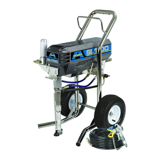
AIRLESSCO SL1100 Operation And Repair Manual
Airless 3000 psi (20.7mpa, 207 bar) maximum working pressure
Hide thumbs
Also See for SL1100:
- Service & operation manual (32 pages) ,
- Operation - repair - parts (35 pages) ,
- Service & operation manual (36 pages)
Table of Contents
Advertisement
Operation/Repair/Parts
Airless Paint Sprayer
For application of architectural paints and coatings. For professional use only.
Airlessco - SL1100 (24F572)
AllPro - Mustang 11000 (24F584)
3000 psi (20.7MPa, 207 bar) Maximum Working Pressure
Important Safety Instructions
Read all warnings and instructions in this
manual. Save these instructions.
Related Manuals
Gun Manual
312363 - English
312364 - Spanish
312365 - French
3A1184A
ENG
ti16141a
Advertisement
Table of Contents

Related Manuals for AIRLESSCO SL1100


Summary of Contents for AIRLESSCO SL1100
- Page 1 Operation/Repair/Parts 3A1184A Airless Paint Sprayer For application of architectural paints and coatings. For professional use only. Airlessco - SL1100 (24F572) AllPro - Mustang 11000 (24F584) 3000 psi (20.7MPa, 207 bar) Maximum Working Pressure Important Safety Instructions Read all warnings and instructions in this manual.
- Page 2 Warnings Warnings The following warnings are for the setup, use, grounding, maintenance, and repair of this equipment. The exclama- tion point symbol alerts you to a general warning and the hazard symbols refer to procedure-specific risks. When these symbols appear in the body of this manual, refer back to these Warnings. Product-specific hazard symbols and warnings not covered in this section may appear throughout the body of this manual where applicable.
- Page 3 All parts of the spray system, including the pump, hose assembly, spray gun, and objects in and around the spray area shall be properly grounded to protect against static discharge and sparks. Use Airlessco conductive or grounded high-pressure airless paint sprayer hoses.
- Page 4 • Do not kink or over-bend the hose. • Do not expose the hose to temperatures or to pressures in excess of those specified by Airlessco. • Do not use the hose as a strength member to pull or lift the equipment.
- Page 5 Warnings WARNING WARNING WARNING WARNING MOVING PARTS HAZARD Moving parts can pinch, cut or amputate fingers and other body parts. • Keep clear of moving parts. • Do not operate equipment with protective guards or covers removed. • Pressurized equipment can start without warning. Before checking, moving, or servicing equipment, follow the Pressure Relief Procedure and disconnect all power sources.
-
Page 6: Component Identification
Component Identification Component Identification ti16142a ti14791a ti14790a Power switch Turns sprayer ON and OFF Fuse 20 AMP Pressure Control Knob Adjusts pressure. Turn clockwise to increase pressure and counterclockwise to decrease pressure. Prime/Pressure (PR) Relief Valve Primes pump and relieves pressure from gun, hose and tip. Prime/Pressure (PR) Relief Valve Open Relieves pressure from gun, hose and tip and primes the unit Position... -
Page 7: Operation
Operation Operation Pressure Relief Procedure 5. Re-engage gun trigger lock and close Prime/Pres- sure Relief Valve. To reduce risk of injury, follow this pressure relief pro- cedure whenever you see this symbol throughout this manual, Also, perform this procedure whenever you: •... -
Page 8: Prime And Flush Storage Fluid
Operation Fill the Packing Nut/Wet Cup Flushing 1. Fill the Packing Nut/Wet Cup with 5 drops of Air- lessco Throat Seal Oil (TSO). • To reduce the risk of static sparking, which can cause fire or explosion, always hold a metal part of the gun firmly against the metal pail when flushing. -
Page 9: Adjusting The Pressure
Operation 7. Point the gun into the metal pail and hold a metal After ensuring the gun trigger lock is engaged, part of the gun firmly against the pail. Maintain firm attach tip and safety guard. metal to metal contact between gun and container. Turn the engine ON/OFF switch to the “ON”... -
Page 10: Short Term
1. Flush sprayer with compatible solvent before stor- rate Gun Manual supplied with the gun. ing, then fill the pump and hoses with an oil based solvent such as mineral spirits or Graco or Airlessco 3. If spraying water-based material or a material that Pump Armor. -
Page 11: Regular Maintenance
2. Keep displacement pump packing nut/wet cup 1/3 Motor Brushes full of Airlessco Throat Seal Oil at all times. The TSO helps protect the packings and rod. Motor brushes need periodic inspection and replace- ment as wear indicates. -
Page 12: Replacement Of Belt/Belt Adjustment
Maintenance Replacement of Belt/Belt Servicing the Fluid Pump Adjustment NOTE: Before disassembling the sprayer refer to Trou- bleshooting to try and resolve the problem. NOTE: The Cog Belt System does not require align- ment. When upper sheave is placed on motor shaft it is Fluid Pump Disconnect pushed on until a positive stop is reached. - Page 13 Maintenance Fluid Pump Reinstall 4. Remove the retaining ring from the packing nut and insert into coupling halves. 1. Loosen the packing nut and extend piston rod to fully up position. Slip sleeve over the piston rod. ti15998a ti16033a 5. Secure the fluid pump housing to the tie rods and screw locknuts with washers on loosely.
-
Page 14: Servicing Inlet Nut And Outlet Valve
Maintenance Servicing Inlet Nut and Outlet Valve Inlet Valve 1. Using the rod collar tool (865008), unscrew the suc- tion nut (6), containing suction seat support (5), off of the fluid body. 2. Remove suction seat (3), O-ring (2), suction ball (1) and suction ball guide (8) with O-ring (2). -
Page 15: Packing Replacement Procedures
Maintenance Packing Replacement Procedures Disassembly of the Fluid Pump 6. Take assembled glands and packings (13 pieces) and slide onto the lower half of the piston. 1. Unscrew and remove the packing nut (2). 7. Take the spacer (4) and slide over the top of the pis- 2. - Page 16 Maintenance 17. Thread the packing nut (2) into the top of the fluid 19. Take the completed suction valve assembly and body (3) and tighten hand tight. place it into the bottom of the fluid body (3), with the rounded side fitting inside. 18.
-
Page 17: Pressure Control Assembly Calibration
Maintenance Pressure Control Assembly Calibration Pressure Calibration NOTE: Anytime a sensor or pressure control assembly (board) or both are replaced, the following calibrations 1. Complete the ZERO calibration, as per “ZERO CAL- must be performed. IBRATION” prior to commencing this calibration. NOTE: Pressure control assemblies (boards) are now 2. -
Page 18: Replacement Of Electrical Components
Maintenance Phase Limit Calibration Sensor Formerly known as the low voltage or master voltage 1. Remove the screws and lower the pressure control calibration. assembly. 2. Disconnect sensor lead from the board. 1. Attach a 50’, 1/4” airless hose, airless gun with .017 tip and a 5000 psi glycerin filled pressure gauge to 3. -
Page 19: Liquid Crystal Display (Lcd)
Maintenance Liquid Crystal Display (LCD) 1. Ensure the power switch is OFF and the machine is unplugged. 2. Detach the pressure control assembly from the frame by unscrewing the eight screws. 3. Disconnect the LCD lead from the pressure control assembly. -
Page 20: Troubleshooting
Troubleshooting Troubleshooting General Problem Cause Solution Unit doesn’t prime Airleak due to loose suction nut Tighten suction nut. Airleak due to worn o-rings Replace o-ring (110636) on suction seat and o-ring (867390) below suction seat. Stuck or fouled balls Service inlet and outlet valves. Prime/Pressure Relief valve not Clean or replace Prime Valve (866428) opening... - Page 21 Troubleshooting Problem Cause Solution Power Source Using a Phillips Head screwdriver, remove the eight screws holding the pressure control assembly. Locate the red light on the board indicating there is power. If the light is ON, see Pressure Control Assembly (Board). If the light is OFF, locate the L1 and L2 termi- nals on the board.
-
Page 22: Airless Spray Gun
Troubleshooting Problem Cause Solution Sensor Plug another sensor board into the board and perform the zero calibration procedure. If the machine starts to run, the sensor is bad. If there is no replacement sensor available, use a multi-meter to test the resistance across the red and black wires of the sensor (be sure to test the plug). - Page 23 Troubleshooting Problem Cause Solution Thin distribution in center of Worn tip Change to new tip pattern “horns” Wrong tip Use tip with narrow spray angle Thick skin on work Material too viscous Thin cautiously Application too heavy Reduce pressure and/or use tip in next smaller tip size Coating fails to close and Material too viscous...
-
Page 24: Paint System
Parts Parts Paint System ti16145a Ref. Part Description Qty. Ref. Part Description Qty. 866428 Prime Valve 867309 Nipple (3/8”-1/4”) 24D688 Drain Hose 867188 Elbow 866282 Pressure Control Assembly (110V) 866123 Manifold Filter 301308 Hose 866334 Sensor 867311 Nipple 301337 Screw 867400 Hose 867420 Plug (3/8”) 121112 Screw... -
Page 25: Manifold Filter
Parts Manifold Filter (865627) ti16052a Ref. Part Description Qty. Ref. Part Description Qty. 867145 Base 867077 Base 301356 Spring 867004 Swivel 867377 O-Ring 867420 Plug 3/8” 867214 Filter 60 Mesh 867309 Nipple 3/8”M x 1/4”M 867647 Support 867417 Plug 1/4” 3A1184A... -
Page 26: Fluid Pump
Parts Fluid Pump Ref. Part Description Qty. 866143 Gearbox 1” (1100/1110E) 301320 Cover 867529 Screw 301105 Hook 301046 Rod End 867468 Retaining Ring 866074 Coupling Set 866069 Retaining Ring 301467 Front Shield 866267 SL Paint Pump Assembly 866241 Suction Nut 140051 Nut 140035 Lock Washer 301173 Bracket-Return Tube... -
Page 27: Inlet And Outlet Valves
Parts Inlet and Outlet Valves Ref. Part Description Qty. 867051 Ball 556562 O-Ring 867574 Suction Seat 866306 Retainer 866400 Support, Suction Seat 866241 Nut ti16143a Ref. Part Description Qty. 187330 Piston Rod 866307 Ball Guide 867047 Outlet Ball 104319 O-Ring 867575 Outlet Seat 187020 Outlet Seat Support ti16144a... -
Page 28: Complete Sprayer
Parts Complete Sprayer 36, 37, 38, 39, 41 22 23 ti16146a 3A1184A... - Page 29 Side (not shown) 301165 Wheel 16F578 Label, SL1100, Front (not shown) 301316 Rubber Edge 1.17’ (makes 2) 16F579 Label, SL1100, Left Side (not shown) 1 301337 Screw 16F580 Label, SL1100, Right Side (not shown) 140029 Washer 342473▲ Label, Warning (not shown) 342506▲...
-
Page 30: Packing Replacement
Parts Packing Replacement ti16002a ti16001a Ref. Part Description Qty. Ref. Part Description Qty. 866269 Piston Rod 556562 O-Ring 866056 Packing Nut 867689 Packing Leather 866295 Fluid Body 866018 Male Gland 866362 Spacer 867693 Packing Polyethylene 104319 O-Ring 866100 Female Adaptor 866307 Ball Guide 867083 Belleville Springs 867047 Outlet Ball... -
Page 31: Suction Assemblies
Parts Suction Assemblies Ref. Part Description Qty. 301594 Suction Assembly 187090 Inlet Strainer 241920 Threaded Deflector 867759 Male Connector 867758 Drain Hose 866211 Clip 24D688 Return Hose Assembly* ti16147a Prime Valve (866428) Ref. Part Description Qty. 865013 Adaptor 235014 Drain Valve 867102 Cam 867404 Pin 867263 Handle... -
Page 32: Electrical System
Parts Electrical System BLACK GREEN & A2 A1 INHIBIT SWITCH S1 S2 LCD ZERO PRESSURE LCD SET ON-SL PHASE LIMIT P-ZR SENSOR DISPLAY ZERO POWER YELLOW LIGHT LIGHT ti16148a Ref. Part Description Qty. Ref. Part Description Qty. 331168 Electrical Cord 110V 866282 Pressure Control Assembly 110V 1 331185 Strain Relief... -
Page 33: Electrical Components
Parts Electrical Components ti16149a Ref. Part Description Qty. Ref. Part Description Qty. 867327 Nut 331360 Window 867760 Plastic Washer 867547 Screw 331377 Display Board Assembly (PSI) 1 865651 LCD Kit (PSI) 117281 Spacer 3A1184A... -
Page 34: Technical Data
Technical Data Technical Data Power requirements ........120V AC, 60 hz, 11A, 1 phase Generator required. - Page 35 Notes Notes 3A1184A...
-
Page 36: Airlessco Standard Warranty
With the exception of any special, extended, or limited warranty published by Airlessco, Airlessco will, for a period of twelve months from the date of sale, repair or replace any part of the equipment determined by Airlessco to be defective.