Table of Contents
Advertisement
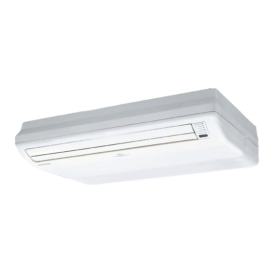
AIR CONDITIONER
INDOOR UNIT
Floor/Ceiling Type
INSTALLATION MANUAL
INSTALLATION MANUAL
For authorized service personnel only.
INSTALLATIONSANLEITUNG
Nur für autorisiertes Personal.
MANUEL D'INSTALLATION
Pour le personnel agréé uniquement.
MANUAL DE INSTALACIÓN
Solo para personal autorizado.
MANUALE D'INSTALLAZIONE
Ad uso esclusivo del personale autorizzato.
ΕΓΧΕΙΡΙΔΙΟ ΕΓΚΑΤΑΣΤΑΣΗΣ
Για εξουσιοδοτημένο προσωπικό σέρβις.
MANUAL DE INSTALAÇÃO
Apenas para técnicos autorizados.
РУКОВОДСТВО ПО УСТАНОВКЕ
Для уполномоченного персонала.
MONTAJ KILAVUZU
Yetkili servis personeli içindir.
PART NO. 9374318445-05
Advertisement
Table of Contents

Related Manuals for Fujitsu Ceiling Type


Summary of Contents for Fujitsu Ceiling Type
-
Page 1: Installation Manual
AIR CONDITIONER INDOOR UNIT Floor/Ceiling Type INSTALLATION MANUAL INSTALLATION MANUAL For authorized service personnel only. INSTALLATIONSANLEITUNG Nur für autorisiertes Personal. MANUEL D'INSTALLATION Pour le personnel agréé uniquement. MANUAL DE INSTALACIÓN Solo para personal autorizado. MANUALE D'INSTALLAZIONE Ad uso esclusivo del personale autorizzato. -
Page 2: Table Of Contents
PART NO. 9374318445-05 This appliance is not intended for use by persons (including children) with reduced INDOOR UNIT (Floor/Ceiling Type) physical, sensory or mental capabilities, or lack of experience and knowledge, unless they have been given supervision or instruction concerning use of the appliance by a Contents person responsible for their safety. -
Page 3: Optional Parts
Name and Shape Q’ty Name and Shape Q’ty 3. INSTALLATION WORK Operating Manual Installation Manual (This manual) Especially, the installation place is very important for the split type air conditioner because it is very diffi cult to move from place to place after the fi rst installation. 3.1. -
Page 4: Installation The Unit
B. Ceiling type When installing set to wall install the accessory wall bracket at the position as shown in the fi gure, and mount the set to it. Ceiling Left Right Indoor unit Wall bracket Side of set Ceiling Unit : mm B. -
Page 5: Pipe Installation
B-3. Installing Brackets Do not use copper pipes that have a collapsed, deformed, or discolored portion (es- Install the bracket with nuts, spring washers. pecially on the interior surface). Otherwise, the expansion valve or capillary tube may Bracket (Left) become blocked with contaminants. Ceiling panel Special nut A Improper pipe selection will degrade performance. -
Page 6: Installing Heat Insulation
4.3.2 Bending pipes Indoor unit • The pipes are shaped by your hands or pipe bender. Be careful not to collapse them. • Do not bend the pipes at an angle more than 90°. • When pipes are repeatedly bend or stretched, the material will harden, making it diffi cult to bend or stretch them any more. -
Page 7: Electrical Wiring
(4) Use an appropriate screwdriver to tighten the terminal screws. Do not use a screw- B. Ceiling type driver that is too small, otherwise, the screw heads may be damaged and prevent the Be sure to arrange the drain hose so that it is leveled lower than the drain hose connect- screws from being properly tightened. -
Page 8: Wiring System Diagram
Simultaneous twin (18, 22, 24 type only) 6.1. Wiring system diagram Junction box Connection cable (Local purchase) Indoor unit (Primary) Outdoor unit Connection diagrams Earth (Ground) line Standard pair Connection cable Outdoor unit Indoor unit Earth (Ground) line Earth (Ground) line Indoor unit Power line (Secondary) -
Page 9: Floor/Ceiling Select Switch
It may cause erroneous operation. 6.4. Floor/ceiling select switch This unit was set for use as a ceiling type at the factory. When using the unit as a fl oor type, perform the following settings in FUNCTION SET- TING. (Refer to 9. FUNCTION SETTING.) Setting the Cooler Room Temperature Correction →... -
Page 10: Load Batteries (R03/Lr03 × 2)
2. Mount the cover plate (left) 8.2. Installing the remote controller holder Join the cover plates (left) and mount with the screw (M4 × 10). Cover plate (Left) CAUTION Check that the indoor unit correctly receives the signal from the remote controller, then install the remote controller holder. -
Page 11: Function Setting
STEP 2 (6) Indoor room temperature sensor switching function Selecting the Function Number and Setting Value (Only for Wired remote controller) Press the SET TEMP. ( ) buttons The following settings are needed using the Wired remote controller temperature sensor to select the function number. -
Page 12: Special Installation Methods
NOTE If no buttons are pressed within 30 seconds after the signal code is displayed, the sys- Be sure to set the R.C. address sequentially. tem returns to the original clock display. In this case, start again from step 1. Set the primary and secondary (Remote controller setting) The air conditioner signal code is set to A prior to shipment. -
Page 13: Test Run
Set the R.C. address (DIP switch setting) Simultaneous Simultaneous Standard Standard Set the R.C. address of each indoor unit using the DIP switches on the indoor unit pair pair twin triple circuit board. (See the following table and fi gure.) Outdoor The DIP switches are normally set to make the R.C. -
Page 14: Check List
[Using the wired remote controller] (Option) • For the operation method, refer to the operating manual. Stop the air conditioner operation. Press the MODE button and the FAN button simultane- ously for 2 seconds or more to start the test run. Press the START/STOP button to stop the test run. -
Page 15: Troubleshooting
Troubleshooting Outdoor unit main PCB model ● ● ◊ [Troubleshooting with the indoor display] information error or communica- tion error Troubleshooting at the display is possible either on the wired or wireless remote controller. Inverter error ● ● ◊ OPERATION Lamp (green) Active fi...